Transcription
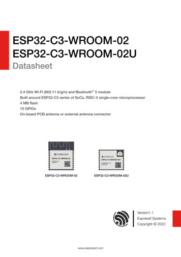
ESP32 C3 WROOM 02ESP32 C3 WROOM 02UDatasheet2.4 GHz Wi Fi (802.11 b/g/n) and Bluetooth 5 moduleBuilt around ESP32 C3 series of SoCs, RISC V single core microprocessor4 MB flash15 GPIOsOn board PCB antenna or external antenna connectorESP32 C3 WROOM 02ESP32 C3 WROOM 02UVersion1.1Espressif SystemsCopyright 2022www.espressif.com
1 Module Overview1 Module OverviewNote:Check the link or the QR code to make sure that you use the latest version of this /documentation/esp32-c3-wroom-02 datasheet en.pdf1.1 FeaturesBluetooth CPU and On Chip Memory ESP32-C3 embedded, 32-bit RISC-V single-core Bluetooth LE: Bluetooth 5, Bluetooth meshprocessor, up to 160 MHz Speed: 125 Kbps, 500 Kbps, 1 Mbps, 2 Mbps 384 KB ROM Advertising extensions 400 KB SRAM (16 KB for cache) Multiple advertisement sets 8 KB SRAM in RTC Channel selection algorithm #2Wi Fi Internal co-existence mechanism between Wi-Fiand Bluetooth to share the same antenna IEEE 802.11 b/g/n-compliantPeripherals Center frequency range of operating channel:2412 2484 MHz GPIO, SPI, UART, I2C, I2S, remote control Supports 20 MHz, 40 MHz bandwidth in 2.4 GHzperipheral, LED PWM controller, general DMAbandcontroller, TWAI controller (compatible with ISO11898-1, i.e. CAN Specification 2.0), USB 1T1R mode with data rate up to 150 MbpsSerial/JTAG controller, temperature sensor, SAR Wi-Fi Multimedia (WMM)ADC, general-purpose timers, watchdog timers TX/RX A-MPDU, TX/RX A-MSDUIntegrated Components on Module Immediate Block ACK Fragmentation and defragmentation 40 MHz crystal oscillator Transmit opportunity (TXOP) 4 MB SPI flash Automatic Beacon monitoring (hardware TSF)Antenna Options 4 virtual Wi-Fi interfaces On-board PCB antenna Simultaneous support for Infrastructure BSS in(ESP32-C3-WROOM-02)Station mode, SoftAP mode, Station SoftAP External antenna via a connectormode, and promiscuous mode(ESP32-C3-WROOM-02U)Note that when ESP32-C3 series scans in Stationmode, the SoftAP channel will change along withOperating Conditionsthe Station channel 802.11mc FTMEspressif Systems Operating voltage/Power supply: 3.0 3.6 V2ESP32-C3-WROOM-02 & WROOM-02U Datasheet v1.1Submit Documentation Feedback
1 Module Overview Operating ambient temperature: Green certification: RoHS/REACH– 85 C version module: –40 85 CTest– 105 C version module: –40 105 C HTOL/HTSL/uHAST/TCT/ESD/Latch-upCertification RF certification: See certificates1.2 DescriptionESP32-C3-WROOM-02 and ESP32-C3-WROOM-02U are two general-purpose Wi-Fi and Bluetooth LEmodules. The rich set of peripherals and high performance make the two modules an ideal choice for smarthomes, industrial automation, health care, consumer electronics, etc.ESP32-C3-WROOM-02 and ESP32-C3-WROOM-02U both feature a 4 MB external SPI flash.ESP32-C3-WROOM-02 comes with a on-board PCB antenna. ESP32-C3-WROOM-02U comes with aconnector for an external antenna.The ordering information for the two modules is as follows:Table 1: Ordering InformationModuleChipOrdering codeembeddedFlashAmbientModuleTemp. ( C)dimensions (mm)ESP32-C3-WROOM-02ESP32-C3-WROOM-02-N4–40 85(ANT)ESP32-C3-WROOM-02-H4–40 P32-C3-WROOM-02U-H4ESP32-C34 MB–40 85–40 10518.0 20.0 3.218.0 14.3 3.2ESP32-C3-WROOM-02 and ESP32-C3-WROOM-02U have two variants: 85 C version operating at –40 85 C 105 C version operating at –40 105 CThe two variants only differ in operating ambient temperature. In this datasheet unless otherwise stated,ESP32-C3-WROOM-02 refers to ESP32-C3-WROOM-02-N4 and ESP32-C3-WROOM-02-H4, andESP32-C3-WROOM-02U refers to ESP32-C3-WROOM-02U-N4 and ESP32-C3-WROOM-02U-H4.At the core of ESP32-C3-WROOM-02 and ESP32-C3-WROOM-02U is ESP32-C3*, which has a 32-bit RISC-Vsingle-core processor.ESP32-C3 integrates a rich set of peripherals, ranging from UART, I2C, I2S, remote control peripheral, LED PWMcontroller, general DMA controller, TWAI controller, USB Serial/JTAG controller, temperature sensor, and ADC. Italso includes SPI, Dual SPI and Quad SPI interfaces.Note:* For more information on ESP32-C3, please refer to ESP32-C3 Series Datasheet.Espressif Systems3ESP32-C3-WROOM-02 & WROOM-02U Datasheet v1.1Submit Documentation Feedback
1 Module Overview1.3 Applications– Wi-Fi speaker Smart Home– Light control– Logger toys and proximity sensing toys– Smart button Smart Agriculture– Smart plug– Smart greenhouse– Indoor positioning– Smart irrigation Industrial Automation– Agriculture robot– Industrial robot Retail and Catering– Mesh network– POS machines– Human machine interface (HMI)– Service robot– Industrial field bus Audio Device Health Care– Internet music players– Health monitor– Live streaming devices– Baby monitor– Internet radio players Consumer Electronics– Smart watch and bracelet Generic Low-power IoT Sensor Hubs– Over-the-top (OTT) devices Generic Low-power IoT Data LoggersEspressif Systems4ESP32-C3-WROOM-02 & WROOM-02U Datasheet v1.1Submit Documentation Feedback
ContentsContents1Module s42Block Diagram83Pin Definitions93.1Pin Layout93.2Pin Description93.3Strapping Pins104Electrical Characteristics124.1Absolute Maximum Ratings124.2Recommended Operating Conditions124.3DC Characteristics (3.3 V, 25 C)124.4Current Consumption Characteristics134.5Wi-Fi Radio144.5.1Wi-Fi RF Standards144.5.2Wi-Fi RF Transmitter (TX) Specifications144.5.3Wi-Fi RF Receiver (RX) Specifications154.6Bluetooth LE Radio164.6.1Bluetooth LE RF Transmitter (TX) Specifications164.6.2Bluetooth LE RF Receiver (RX) Specifications185Module Schematics216Peripheral Schematics237Physical Dimensions and PCB Land Pattern247.1Physical Dimensions247.2Recommended PCB Land Pattern257.3Dimensions of External Antenna Connector278Product Handling288.1Storage Conditions288.2Electrostatic Discharge (ESD)288.3Reflow Profile289Related Documentation and Resources29Revision HistoryEspressif Systems305ESP32-C3-WROOM-02 & WROOM-02U Datasheet v1.1Submit Documentation Feedback
List of TablesList of Tables1Ordering Information32Pin Definitions93Strapping Pins114Parameter Descriptions of Setup and Hold Times for the Strapping Pins115Absolute Maximum Ratings126Recommended Operating Conditions127DC Characteristics (3.3 V, 25 C)128Current Consumption Depending on RF Modes139Current Consumption Depending on Work Modes1310Wi-Fi RF Standards1411TX Power with Spectral Mask and EVM Meeting 802.11 Standards1412TX EVM Test1413RX Sensitivity1514Maximum RX Level1615RX Adjacent Channel Rejection1616Transmitter General Characteristics1617Transmitter Characteristics - Bluetooth LE 1 Mbps1718Transmitter Characteristics - Bluetooth LE 2 Mbps1719Transmitter Characteristics - Bluetooth LE 125 Kbps1720Transmitter Characteristics - Bluetooth LE 500 Kbps1821Receiver Characteristics - Bluetooth LE 1 Mbps1822Receiver Characteristics - Bluetooth LE 2 Mbps1923Receiver Characteristics - Bluetooth LE 125 Kbps1924Receiver Characteristics - Bluetooth LE 500 Kbps19Espressif Systems6ESP32-C3-WROOM-02 & WROOM-02U Datasheet v1.1Submit Documentation Feedback
List of FiguresList of Figures1ESP32-C3-WROOM-02 Block Diagram82ESP32-C3-WROOM-02U Block Diagram83Pin Layout (Top View)94Setup and Hold Times for the Strapping Pins115ESP32-C3-WROOM-02 Schematics216ESP32-C3-WROOM-02U Schematics227Peripheral Schematics238ESP32-C3-WROOM-02 Physical Dimensions249ESP32-C3-WROOM-02U Physical Dimensions2410ESP32-C3-WROOM-02 Recommended PCB Land Pattern2511ESP32-C3-WROOM-02U Recommended PCB Land Pattern2612Dimensions of External Antenna Connector2713Reflow Profile28Espressif Systems7ESP32-C3-WROOM-02 & WROOM-02U Datasheet v1.1Submit Documentation Feedback
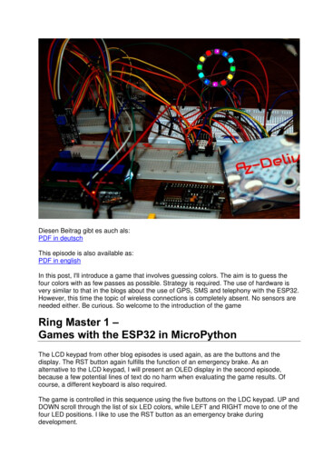
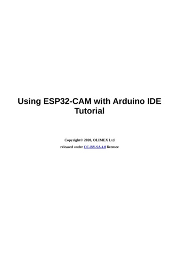
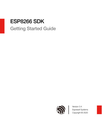
2 Block Diagram2 Block Diagram40 MHzCrystal3V3AntennaRF PVDD SPIENSPI FlashESP32-C3-WROOM-02Figure 1: ESP32 C3 WROOM 02 Block Diagram40 MHzCrystal3V3AntennaRF PVDD SPIENSPI FlashESP32-C3-WROOM-02UFigure 2: ESP32 C3 WROOM 02U Block DiagramEspressif Systems8ESP32-C3-WROOM-02 & WROOM-02U Datasheet v1.1Submit Documentation Feedback
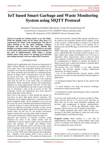
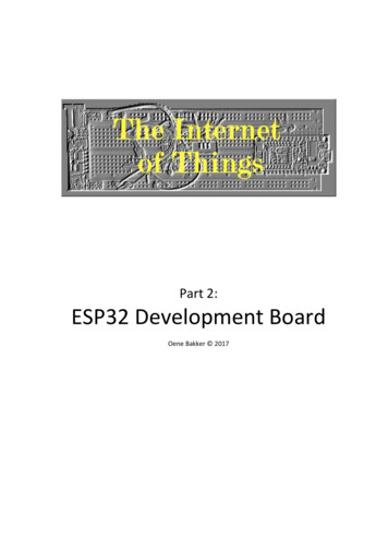
3 Pin Definitions3 Pin Definitions3.1 Pin LayoutThe pin diagram below shows the approximate location of pins on the module. For the actual diagram drawn toscale, please refer to Figure 7.1 Physical Dimensions.Keepout 3GNDGNDGNDGNDPin 010Figure 3: Pin Layout (Top View)3.2 Pin DescriptionThe module has 19 pins. See pin definitions in Table 2.For peripheral pin configurations, please refer to ESP32-C3 Series Datasheet.Table 2: Pin DefinitionsNameNo.3V31Type1 FunctionPPower supplyHigh: on, enables the chip.EN2ILow: off, the chip powers off.Note: Do not leave the EN pin floating.IO43I/O/TGPIO4, ADC1 CH4, FSPIHD, MTMSIO54I/O/TGPIO5, ADC2 CH0, FSPIWP, MTDIIO65I/O/TGPIO6, FSPICLK, MTCKCont’d on next pageEspressif Systems9ESP32-C3-WROOM-02 & WROOM-02U Datasheet v1.1Submit Documentation Feedback
3 Pin DefinitionsTable 2 – cont’d from previous pageName1No.TypeIO76I/O/TGPIO7, FSPID, 10I/O/TGPIO10, FSPICS0RXD11I/O/TGPIO20, U0RXDTXD12I/O/TGPIO21, U0TXDIO1813I/O/TGPIO18, USB D-IO1914I/O/TGPIO19, USB D IO315I/O/TGPIO3, ADC1 CH3IO216I/O/TGPIO2, ADC1 CH2, FSPIQIO117I/O/TGPIO1, ADC1 CH1, XTAL 32K NIO018I/O/TGPIO0, ADC1 CH0, XTAL 32K P1FunctionP: power supply; I: input; O: output; T: high impedance.3.3 Strapping PinsNote:The content below is excerpted from Section Strapping Pins in ESP32-C3 Series Datasheet. For the strapping pin mapping between the chip and modules, please refer to Chapter 5 Module Schematics.ESP32-C3 family has three strapping pins: GPIO2 GPIO8 GPIO9Software can read the values of GPIO2, GPIO8 and GPIO9 from GPIO STRAPPING field in GPIO STRAP REGregister. For register description, please refer to Section GPIO Matrix Register Summary inESP32-C3 Technical Reference Manual.During the chip’s system reset, the latches of the strapping pins sample the voltage level as strapping bits of ”0”or ”1”, and hold these bits until the chip is powered down or shut down.Types of system reset include: power-on reset RTC watchdog reset brownout reset analog super watchdog reset crystal clock glitch detection resetBy default, GPIO9 is connected to the internal pull-up resistor. If GPIO9 is not connected or connected to anexternal high-impedance circuit, the latched bit value will be ”1”Espressif Systems10ESP32-C3-WROOM-02 & WROOM-02U Datasheet v1.1Submit Documentation Feedback
3 Pin DefinitionsTo change the strapping bit values, you can apply the external pull-down/pull-up resistances, or use the hostMCU’s GPIOs to control the voltage level of these pins when powering on ESP32-C3 family.After reset, the strapping pins work as normal-function pins.Table 3 lists detailed booting configurations of the strapping pins.Table 3: Strapping PinsBooting Mode 1PinDefaultSPI BootDownload BootGPIO2N/A11GPIO8N/ADon’t care1GPIO9Internal pull-up10Enabling/Disabling ROM Code Print During BootingPinDefaultFunctionalityWhen the value of eFuse field EFUSE UART PRINT CONTROL is0 (default), print is enabled and not controlled by GPIO8.GPIO8N/A1, if GPIO8 is 0, print is enabled; if GPIO8 is 1, it is disabled.2, if GPIO8 is 0, print is disabled; if GPIO8 is 1, it is enabled.3, print is disabled and not controlled by GPIO8.1The strapping combination of GPIO8 0 and GPIO9 0 is invalid and will trigger unexpected behavior.Figure 4 shows the setup and hold times for the strapping pins before and after the CHIP EN signal goes high.Details about the parameters are listed in Table 4.t0CHIP ENt1VIL nRSTVIHStrapping pinFigure 4: Setup and Hold Times for the Strapping PinsTable 4: Parameter Descriptions of Setup and Hold Times for the Strapping PinsMinParameterDescriptiont0Setup time before CHIP EN goes from low to high0t1Hold time after CHIP EN goes high3Espressif Systems(ms)11ESP32-C3-WROOM-02 & WROOM-02U Datasheet v1.1Submit Documentation Feedback
4 Electrical Characteristics4 Electrical Characteristics4.1 Absolute Maximum RatingsStresses above those listed in Absolute Maximum Ratings may cause permanent damage to the device. Theseare stress ratings only and functional operation of the device at these or any other conditions beyond thoseindicated under Recommended Operating Conditions is not implied. Exposure to absolute-maximum-ratedconditions for extended periods may affect device reliability.Table 5: Absolute Maximum RatingsSymbolParameterMinMaxUnitVDD33Power supply voltage–0.33.6VTST OREStorage temperature–40105 C4.2 Recommended Operating ConditionsTable 6: Recommended Operating ConditionsSymbolParameterMinTypMaxVDD33IV DDTAOperating ambient temperaturePower supply voltage3.03.33.6VCurrent delivered by external power supply0.5——A–40—85 C version105 C versionUnit85 C1054.3 DC Characteristics (3.3 V, 25 C)Table 7: DC Characteristics (3.3 V, 25 C)SymbolParameterCINPin capacitanceVIHMinTyp—High-level input voltage0.75 VDD1Max2—Unit—pF1VDD 0.3V1VILLow-level input voltage–0.3—0.25 VDDIIHHigh-level input current——50nALow-level input current——50nA——VIILVOHVOL22High-level output voltage0.8 VDDLow-level output voltage11V——0.1 level source current (VDD 3.3 V,VOH 2.64 V, PAD DRIVER 3)Low-level sink current (VDD1 3.3 V, VOL 0.495 V, PAD DRIVER 3)RP UPull-up resistor—45RP DPull-down resistor—45VIH nRSTChip reset release voltage0.75 VDD1—1VDD 0.3VCont’d on next pageEspressif Systems12ESP32-C3-WROOM-02 & WROOM-02U Datasheet v1.1Submit Documentation Feedback
4 Electrical CharacteristicsTable 7 – cont’d from previous pageSymbolParameterVIL nRSTMinChip reset voltageTyp–0.31VDD is the I/O voltage for a particular power domain of pins.2VOH and VOL are measured using high-impedance load.—MaxUnit0.25 VDD1V4.4 Current Consumption CharacteristicsWith the use of advanced power-management technologies, the module can switch between different powermodes. For details on different power modes, please refer to Section Low Power Managementin ESP32-C3 Series Datasheet.Table 8: Current Consumption Depending on RF ModesWork modeDescriptionTXActive (RF working)RX1Peak (mA)802.11b, 1 Mbps, @20.5 dBm345802.11g, 54 Mbps, @18 dBm285802.11n, HT20, MCS7, @17.5 dBm280802.11n, HT40, MCS7, @17 dBm280802.11b/g/n, HT2082802.11n, HT4084The current consumption measurements are taken with a 3.3 V supply at 25 C of ambienttemperature at the RF port. All transmitters’ measurements are based on a 100% duty cycle.2The current consumption figures for in RX mode are for cases when the peripherals are disabled and the CPU idle.Table 9: Current Consumption Depending on Work ModesWork modeModem-sleep1, 2DescriptionThe CPU ispowered on3TypUnit160 MHz20mA80 MHz15mA130µALight-sleep—Deep-sleepRTC timer RTC memory5µAPower offCHIP EN is set to low level, the chip is powered off1µA1The current consumption figures in Modem-sleep mode are for cases where the CPU is powered on andthe cache idle.2When Wi-Fi is enabled, the chip may switch between Active and Modem-sleep modes. Therefore, currentconsumption changes accordingly.3In practice, software can adjust CPU’s frequency according to CPU load to reduce current consumption.Espressif Systems13ESP32-C3-WROOM-02 & WROOM-02U Datasheet v1.1Submit Documentation Feedback
4 Electrical Characteristics4.5 Wi Fi Radio4.5.1 Wi Fi RF StandardsTable 10: Wi Fi RF StandardsNameDescriptionCenter frequency range of operating channel12412 2484 MHzWi-Fi wireless standardIEEE 802.11b/g/n11b: 1, 2, 5.5 and 11 Mbps20 MHzData rate11g: 6, 9, 12, 18, 24, 36, 48, 54 Mbps11n: MCS0-7, 72.2 Mbps (Max)40 MHz11n: MCS0-7, 150 Mbps (Max)Antenna type1PCB antenna, external antenna connectorDevice should operate in the center frequency range allocated by regional regulatory authorities.Target center frequency range is configurable by software.2For the modules that use external antenna connectors, the output impedance is 50 Ω. For othermodules without external antenna connectors, the output impedance is irrelevant.4.5.2 Wi Fi RF Transmitter (TX) SpecificationsTarget TX power is configurable based on device or certification requirements. The default characteristics areprovided in Table 11.Table 11: TX Power with Spectral Mask and EVM Meeting 802.11 StandardsMinTypMax(dBm)(dBm)(dBm)802.11b, 1 Mbps—20.5—802.11b, 11 Mbps—20.5—802.11g, 6 Mbps—20.0—802.11g, 54 Mbps—18.0—802.11n, HT20, MCS0—19.0—802.11n, HT20, MCS7—17.5—802.11n, HT40, MCS0—18.5—802.11n, HT40, MCS7—17.0—RateTable 12: TX EVM TestRateMinTypSL1(dB)(dB)(dB)802.11b, 1 Mbps, @20.5 dBm—–24.5–10802.11b, 11 Mbps, @20.5 dBm—–25.0–10802.11g, 6 Mbps, @20 dBm—–23.0–5802.11g, 54 Mbps, @18 dBm—–28.0–25802.11n, HT20, MCS0, @19 dBm—–23.5–5Cont’d on next pageEspressif Systems14ESP32-C3-WROOM-02 & WROOM-02U Datasheet v1.1Submit Documentation Feedback
4 Electrical CharacteristicsTable 12 – cont’d from previous pageRateMinTypSL1(dB)(dB)(dB)802.11n, HT20, MCS7, @17.5 dBm—–29.5–27802.11n, HT40, MCS0, @18.5 dBm—–26.5–5802.11n, HT40, MCS7, @17 dBm—–29.5–271SL stands for standard limit value.4.5.3 Wi Fi RF Receiver (RX) SpecificationsTable 13: RX SensitivityMinTypMax(dBm)(dBm)(dBm)802.11b, 1 Mbps—–98.0—802.11b, 2 Mbps—–96.0—802.11b, 5.5 Mbps—–93.0—802.11b, 11 Mbps—–88.6—802.11g, 6 Mbps—–93.0—802.11g, 9 Mbps—–92.0—802.11g, 12 Mbps—–90.8—802.11g, 18 Mbps—–88.4—802.11g, 24 Mbps—–85.4—802.11g, 36 Mbps—–82.0—802.11g, 48 Mbps—–78.0—802.11g, 54 Mbps—–76.4—802.11n, HT20, MCS0—–93.0—802.11n, HT20, MCS1—–90.8—802.11n, HT20, MCS2—–88.2—802.11n, HT20, MCS3—–84.6—802.11n, HT20, MCS4—–81.4—802.11n, HT20, MCS5—–77.4—802.11n, HT20, MCS6—–75.4—802.11n, HT20, MCS7—–74.4—802.11n, HT40, MCS0—–90.0—802.11n, HT40, MCS1—–87.6—802.11n, HT40, MCS2—–84.8—802.11n, HT40, MCS3—–81.8—802.11n, HT40, MCS4—–78.4—802.11n, HT40, MCS5—–74.4—802.11n, HT40, MCS6—–72.6—802.11n, HT40, MCS7—–71.2—RateEspressif Systems15ESP32-C3-WROOM-02 & WROOM-02U Datasheet v1.1Submit Documentation Feedback
4 Electrical CharacteristicsTable 14: Maximum RX LevelMinTypMax(dBm)(dBm)(dBm)802.11b, 1 Mbps—5—802.11b, 11 Mbps—5—802.11g, 6 Mbps—5—802.11g, 54 Mbps—0—802.11n, HT20, MCS0—5—802.11n, HT20, MCS7—0—802.11n, HT40, MCS0—5—802.11n, HT40, MCS7—0—RateTable 15: RX Adjacent Channel RejectionRateMinTypMax(dB)(dB)(dB)802.11b, 1 Mbps—35—802.11b, 11 Mbps—35—802.11g, 6 Mbps—31—802.11g, 54 Mbps—20—802.11n, HT20, MCS0—31—802.11n, HT20, MCS7—16—802.11n, HT40, MCS0—25—802.11n, HT40, MCS7—11—4.6 Bluetooth LE Radio4.6.1 Bluetooth LE RF Transmitter (TX) SpecificationsTable 16: Transmitter General CharacteristicsParameterMinMaxUnitRF transmit power—0—dBmGain control step—3—dB–27—18dBmRF power control rangeEspressif SystemsTyp16ESP32-C3-WROOM-02 & WROOM-02U Datasheet v1.1Submit Documentation Feedback
4 Electrical CharacteristicsTable 17: Transmitter Characteristics Bluetooth LE 1 MbpsParameterDescriptionIn-band emissionsModulation characteristicsCarrier frequency offsetCarrier frequency driftMinTypMaxUnitF F0 2 MHz—–37.62—dBmF F0 3 MHz—–41.95—dBmF F0 3 MHz—–44.48—dBm f 1avg—245.00—kHz f 2max—208.00—kHz f 2avg / f 1avg—0.93————–9.00—kHz f0 fn n 2, 3, 4, .k—1.17—kHz f1 f0 —0.30—kHz fn fn 5 n 6, 7, 8, .k—4.90—kHzTable 18: Transmitter Characteristics Bluetooth LE 2 MbpsParameterDescriptionIn-band emissionsModulation characteristicsCarrier frequency offsetCarrier frequency driftMinTypMaxUnitF F0 4 MHz—–43.55—dBmF F0 5 MHz—–45.26—dBmF F0 5 MHz—–47.00—dBm f 1avg—497.00—kHz f 2max—398.00—kHz f 2avg / f 1avg—0.95————–9.00—kHz f0 fn n 2, 3, 4, .k—0.46—kHz f1 f0 —0.70—kHz fn fn 5 n 6, 7, 8, .k—6.80—kHzTable 19: Transmitter Characteristics Bluetooth LE 125 KbpsParameterIn-band emissionsModulation characteristicsCarrier frequency offsetCarrier frequency driftEspressif SystemsDescriptionMinTypMaxUnitF F0 2 MHz—–37.90—dBmF F0 3 MHz—–41.00—dBmF F0 3 MHz—–42.50—dBm f 1avg—252.00—kHz f 1max—200.00—kHz——–13.70—kHz f0 fn n 1, 2, 3, .k—1.52—kHz f0 f3 —0.65—kHz fn fn 3 n 7, 8, 9, .k—0.70—kHz17ESP32-C3-WROOM-02 & WROOM-02U Datasheet v1.1Submit Documentation Feedback
4 Electrical CharacteristicsTable 20: Transmitter Characteristics Bluetooth LE 500 KbpsParameterDescriptionIn-band emissionsModulation characteristicsCarrier frequency offsetCarrier frequency driftMinTypMaxUnitF F0 2 MHz—–37.90—dBmF F0 3 MHz—–41.30—dBmF F0 3 MHz—–42.80—dBm f 2avg—220.00—kHz f 2max—205.00—kHz——–11.90—kHz f0 fn n 1, 2, 3, .k—1.37—kHz f0 f3 —1.09—kHz fn fn 3 n 7, 8, 9, .k—0.51—kHz4.6.2 Bluetooth LE RF Receiver (RX) SpecificationsTable 21: Receiver Characteristics Bluetooth LE 1 MbpsParameterDescriptionSensitivity @30.8% PER——–97—dBmMaximum received signal @30.8% PER——10—dBmCo-channel C/I——7—dBF F0 1 MHz—–4—dBF F0 – 1 MHz—–4—dBF F0 2 MHz—–29—dBF F0 – 2 MHz—–31—dBF F0 3 MHz—–33—dBF F0 – 3 MHz—–35—dBF F0 4 MHz—–35—dBF F0 – 4 MHz—–37—dB——–35—dBF Fimage 1 MHz—–40—dBF Fimage – 1 MHz—–33—dB30 MHz 2000 MHz—–6—dBm2003 MHz 2399 MHz—–26—dBm2484 MHz 2997 MHz—–25—dBm3000 MHz 12.75 GHz—–5—dBm——–30—dBmAdjacent channel selectivity C/IImage frequencyAdjacent channel to image frequencyOut-of-band blocking performanceIntermodulationEspressif Systems18MinTypMaxUnitESP32-C3-WROOM-02 & WROOM-02U Datasheet v1.1Submit Documentation Feedback
4 Electrical CharacteristicsTable 22: Receiver Characteristics Bluetooth LE 2 MbpsParameterDescriptionSensitivity @30.8% PER——–93—dBmMaximum received signal @30.8% PER——5—dBmCo-channel C/I——10—dBF F0 2 MHz—–8—dBF F0 – 2 MHz—–7—dBF F0 4 MHz—–32—dBF F0 – 4 MHz—–34—dBF F0 6 MHz—–39—dBF F0 – 6 MHz—–39—dB——–32—dBAdjacent channel selectivity C/IImage frequencyMinF Fimage 2 MHzAdjacent channel to image –8—dB30 MHz 2000 MHz—–12—dBm2003 MHz 2399 MHz—–30—dBm2484 MHz 2997 MHz—–28—dBm3000 MHz 12.75 GHz—–6—dBm——–29—dBmF Fimage – 2 MHzOut-of-band blocking performanceTypTable 23: Receiver Characteristics Bluetooth LE 125 KbpsParameterDescriptionSensitivity @30.8% PER——–105—dBmMaximum received signal @30.8% PER——10—dBmCo-channel C/I——2—dBF F0 1 MHz—–6—dBF F0 – 1 MHz—–4—dBF F0 2 MHz—–33—dBF F0 – 2 MHz—–41—dBF F0 3 MHz—–37—dBF F0 – 3 MHz—–46—dBF F0 4 MHz—–40—dBF F0 – 4 MHz—–49—dB——–40—dBF Fimage 1 MHz—–46—dBF Fimage – 1 MHz—–37—dBAdjacent channel selectivity C/IImage frequencyAdjacent channel to image frequencyMinTypMaxUnitTable 24: Receiver Characteristics Bluetooth LE 500 KbpsParameterDescriptionMinTypMaxUnitSensitivity @30.8% PER——–101—dBmMaximum received signal @30.8% PER——10—dBmCo-channel C/I——3—dBCont’d on next pageEspressif Systems19ESP32-C3-WROOM-02 & WROOM-02U Datasheet v1.1Submit Documentation Feedback
4 Electrical CharacteristicsTable 24 – cont’d from previous pageParameterAdjacent channel selectivity C/IImage frequencyAdjacent channel to image frequencyEspressif SystemsDescriptionMinTypMaxUnitF F0 1 MHz—–6—dBF F0 – 1 MHz—–7—dBF F0 2 MHz—–34—dBF F0 – 2 MHz—–37—dBF F0 3 MHz—–38—dBF F0 – 3 MHz—–40—dBF F0 4 MHz—–40—dBF F0 – 4 MHz—–42—dB——–40—dBF Fimage 1 MHz—–45—dBF Fimage – 1 MHz—–38—dB20ESP32-C3-WROOM-02 & WROOM-02U Datasheet v1.1Submit Documentation Feedback
43215 Module Schematics5 Module SchematicsThis is the reference design of the module.DDGND XOUTC2TBD21The value of R1 varies with the actualPCB board.GND40MHz( 10ppm)0VDD33GND3U1GNDC1TBDThe values of C1 and C2 vary withthe selection of the crystal.4GNDGNDXINEspressif Systems5330C710uF0.1uFNCRF ANT L2PCB ANTC8TBDGNDGNDVDD SPIGNDTBDC9TBDGNDLNA INGPIO0GPIO1GPIO2CHIP ENGPIO312345678LNA INVDD3P3VDD3P3XTAL 32K PXTAL 32K NGPIO2CHIP ENGPIO3The values of C8, L2 and C9vary with the actual PCB board.NC: No component.ESP32-C3-WROOM-02 & WROOM-02U Datasheet SPICLKSPICS0SPIWPSPIHDVDD SPIVDD3P3 IDSPICLKSPICS0SPIWPSPIHDVDD ND812VDD33MTMSMTDIVDD3P3 T1PCB ANTENNAVCCC6U0TXDU0RXDGPIO19GPIO18GNDC521Submit Documentation FVDDAVDDAXTAL PXTAL 33CHIP .11RXDPin.10IO10CESP32-C3-WROOM-02(pin-out)BFigure 5: ESP32 C3 WROOM 02 SchematicsAATitleESP32-C3-WROOM-02SizeA3Page Name 02 ESP32-C3-WROOM-02 RevV1.6Confidential and Proprietary
54321GND XOUTR1GNDANT1C8CONNTBDTBDC9GNDTBDGNDLNA INGPIO0GPIO1GPIO2CHIP ENGPIO312345678LNA INVDD3P3VDD3P3XTAL 32K PXTAL 32K NGPIO2CHIP ENGPIO3SPIQSPIDSPICLKSPICS0SPIWPSPIHDVDD SPIVDD3P3 CPUThe values of C8, L2 and C9vary with the actual PCB board.NC: No component.U2ESP32-C3-WROOM-02 & WROOM-02U Datasheet 191817R3R4R5100100100R6R7100100CHIP P32-C3-WROOM-02U(pin-out)VDD SPIVDD C128RF ANT it Documentation GND12C7MTMSMTDIVDD3P3 5IO6Pin.6IO7Pin.7IO8Pin.8IO9Pin.9GND40GNDGND40MHz( AXTAL PXTAL The value of R1 varies with the actualPCB board.VDD33GND34GNDC1TBDThe values of C1 and C2 vary withthe selection of the GNDGNDFigure 6: ESP32 C3 WROOM 02U Page Name 02 ESP32-C3-WROOM-02U Thursday, July 22, 2021RevV1.3Confidential and ProprietarySheet21of25 Module SchematicsEspressif SystemsGND
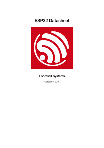
5436 Peripheral Schematics6 Peripheral SchematicsThis is the typical application circuit of the module connected with peripheral components (for example, powersupply, antenna, reset button, JTAG interface, and UART interface).VDD330.1uFR1C3 D 181IO0 R33V3IO0217IO1 R5ENIO1316IO2 2TXDTXD 118 IO8RXDRXD 109 IO9IO10GNDIO10U10 EN0.1uFGNDGNDX132.768kHz(NC)USB D USB D-00VDD3312JP2Boot OptionR2C4R4R6GNDSW1GNDC7GND12pF(NC) C8VDD33 NC: No TFigure 7: Peripheral Schematics Soldering the EPAD to the ground of the base board is not a must, however, it can optimize thermalperformance. If you choose to solder it, please apply the correct amount of soldering paste. To ensure that the power supply to the ESP32-C3 chip is stable during power-up, it is advised to add anRC delay circuit at the EN pin. The recommended setting for the RC delay circuit is usually R 10 kΩ andC 1 µF. However, specific parameters should be adjusted based on the power-up timing of the moduleand the power-up and reset sequence timing of the chip. For ESP32-C3’s power-up and reset sequencetiming diagram, please refer to Section Power Scheme in ESP32-C3 Series Datasheet.54Espressif Systems323ESP32-C3-WROOM-02 & WROOM-02U Datasheet v1.1Submit Documentation Feedback
7 Physical Dimensions and PCB Land Pattern7 Physical Dimensions and PCB Land Pattern7.1 Physical DimensionsUnit: mm18 0.153.2 0.150.40.72.98.0418 x 0.451.150.40.76.72.918 x 0.90.710.512.3715.7Ø18 x 0.90.91.518 x Ø0.551220 0.1560.818 x 0.85Top ViewBottom ViewSide ViewFigure 8: ESP32 C3 WROOM 02 Physical DimensionsUnit: mm18 0.153.2 0.152.750.82.92.90.40.76.718 x 0.92.30.788.8512.750.5Ø18 x 0.90.91.51214.3 0.1515.750.350.70.40.3511.5518 x Ø0.558.0418 x 0.4518 x 0.851.12Top ViewSide ViewBottom ViewFigure 9: ESP32 C3 WROOM 02U Physical DimensionsNote:For information about tape, reel, and product marking, please refer to Espressif Module Package Information.Espressif Systems24ESP32-C3-WROOM-02 & WROOM-02U Datasheet v1.1Submit Documentation Feedback
7 Physical Dimensions and PCB Land Pattern7.2 Recommended PCB Land PatternUnit: mmVia for thermal padCopper6Antenna Area18 x 1.57.118181201.52.90.9 18 x 0.90.40.40.70.76.72.99.9691017.50.50.5Figure 10: ESP32 C3 WROOM 02 Recommended PCB Land PatternEspressif Systems25ESP32-C3-WROOM-02 & WROOM-02U Datasheet v1.1Submit Documentation Feedback
7 Physical Dimensions and PCB Land PatternUnit: mmVia for thermal padCopper1818 x 1.50.76.72.99.96914.31.52.90.9 18 x 0.90.40.40.71.41811017.50.50.5Figure 11: ESP32 C3 WROOM 02U Recommended PCB Land PatternEspressif Systems26ESP32-C3-WROOM-02 & WROOM-02U Datasheet v1.1Submit Documentation Feedback
7 Physical Dimensions and PCB Land Pattern7.3 Dimensions of External Antenna ConnectorESP32-C3-WROOM-02U uses the first generation external antenna connector as shown in Figure 12. Thisconnector is compatible with the following connectors: U.FL Series connector from Hirose MHF I connector from I-PEX AMC connector from AmphenolUnit: mmFigure 12: Dimensions of External Antenna ConnectorEspressif Systems27ESP32-C3-WROOM-02 & WROOM-02U Datasheet v1.1Submit Documentation Feedback
8 Product Handling8 Product Handling8.1 Storage ConditionsThe products sealed in moisture barrier bags (MBB) should be stored in a non-conden
Contents Contents 1 Module Overview 2 1.1 Features 2 1.2 Description 3 1.3 Applications 4 2 Block Diagram 8 3 Pin Definitions 9 3.1 PinLayout 9 3.2 PinDescription 9