Transcription
How to Draw Clock Gearsin VisioByMike MacLeodCopyright Mike MacLeod 2017.This eBook is licensed for your personal enjoyment only and may not be distributedor sold. All rights reserved. No part of this book may be reproduced or transmitted inany form or by any means without written permission of the author.Printed and published by Mike MacLeod,Benoni.South com 20171
How to Draw a Clock Gear in Visio.By Mike MacLeod.Programs required:Forest Moons ‘GearDxf’ - freeA9Tech ‘A9Convertor’ - freeVisio, V3.0 - 2007Step 1. Open Forest Moons ‘GearDxf’ and set the parameters, making sure that youhave a dimension in the ‘Bore hole diameter’ box, then save the file to a folderof your choosing, noting what units you used, i.e. mm or inches.Step2. Open A9Tech ‘A9Convertor’.Load the DXF file that you saved in step 1, by dragging it and droppingit onto the ‘DWG/DXF File Input’ list box.Select ‘DXF’ from the drop down menu for Output file format.Select ‘AutoCAD 2000/2002’ from the drop down menu in the ‘Output fileVersion’ box.Select the folder where you want to save the converted file to and press‘Convert’.Click ‘OK’ to exit program. 20172
Step3. Open Visio and select a ‘New Page’. Set the page units to match the units ofthe original dxf file that you created in GearDxf, i.e. mm or inches.If you’re new to Visio, first read Tips and Tricks lower down.Select ‘Insert/Cad Drawing ’ from the top menu and then load your newlyconverted ‘whatever.dxf’file.A new tab ‘Cad Drawing Properties’ opens, untick ‘Lock Size and Position’as well as ‘Lock Against Deletion’ boxes.Click OK to close.Your gear will now appear with red text at the bottom. 20173
Right click on the gear and select ‘Cad Drawing Object’ then select‘Convert’.Untick layers ‘Notes’ and ‘0’, then select OK.The drawing will now be converted and a warning will appear: ‘The file wasopened but problems occurred’ – ignore this and close it.Click on the red text at the bottom of the drawing and delete it. If awarning says that you can’t, right click and untick the two boxes as we didpreviously by right clicking and selecting Cad Drawing Object/Properties,just in case they have been reset.Highlight the gear again and select ‘Fill’ and choose a colour. At this stagenothing happens. With the gear still highlighted, select from the top menu bar‘Shape/Operations/Fragment’, whereby the gear turns to the colour youselected. While it is still highlighted, click ‘Send to the back’ and the bluecentre circle appears.Now highlight both the gear and the circle and press ‘Fragment’ again.The centre hole should be highlighted, if not, select it and remove the ‘Fill’colour. Set the size to whatever you think the centre boss/hub diameter shouldbe or as called out in your drawing. 20174
To add spokes to the gear, I draw a reference circle to just below the root ofthe teeth, say the same distance away as the height of a tooth.I then draw two rectangles, the same width as my planned spokes and I makethem slightly shorter than the diameter of the inner circle we just drew – theircorners should touch the cirle. Rotate one 90 degrees and centre both on thegear. You should now have a cross in the centre of the gear.Make sure that the inner circle that represents the boss or hub is large enoughto see, if not make it slighly bigger.Using the ‘Arc Tool’, draw a triangle in one of the quadrants formed by thecross, following around the hub circle on the inner corner and the referencecircle on the outer side. Use the guides to push or pull your triangle into shape,then select ‘Corner rounding’ and select a radius. Your triangle will now havenice rounded corners.Copy and paste this triangle into the other three corners and when they’re allaligned, delete the cross rectangles.Now highlight the gear (do not highlight the circles) as well as the fourtriangles and select ‘Fragment’. 20175
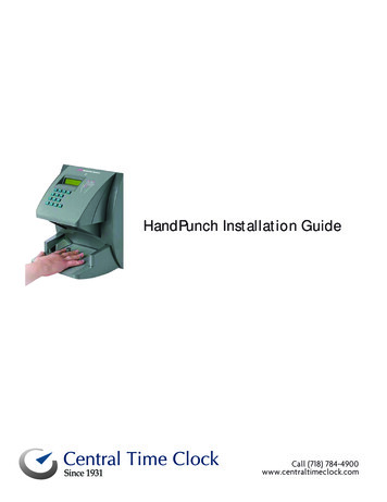
Delete the four triangles and the centre circle and you should be left with yourgear, complete with spokes.Select the gear and ‘Send it to the Back’. Delete any unwanted circles andalignment marks, then select ‘Save as’ and save as a .dxf file. Give it adifferent name so that you don’t mix it up with the others that you created.Views with circles and without circles.You’ll have to optimize the gcode for the one on the left because the circlesrepresent the different thicknesses.Tips and TricksVisio is quick and easy to use, and very accurate and while it is only a 2Dprogram, you can design and manufacture a variety of items. For me the bestthing is to optimize the menu tool bar with the commands you use the most,see my sample below.One of the best features of Visio is the Fragment, Union and Combinecommands, along with the Shift key, allowing us to make complex shapes.In making the gear above, it required just the mouse and the Shift button and atrick I learnt early on and that was to use alignment ticks or lines to aid ingetting things aligned perfectly. It also helps to have the Size & Positionwindow open. This allows you to see the measurements where you can modifythe numbers and angles. I also have a stencil open called ‘Dimension –Engineering, whereby you can add dimensions to your drawing, see below. 20176
When aligning objects, the first item selected, is the master and the next itemselected becomes the slave and will align to the master. In other words, all theitems selected, will align to the first item selected.Here is where the alignment tools help on the tool bar, allowing you to aligntop, bottom, centre or left and right and allows you to quickly draw a design.For example I selected all the circles bydragging the cursor around them usingthe mouse and then selecting theVertical align tool, then the Horizontalone, aligning all the items at once. Youcan also nudge an item into place byhighlighting it and then using the updown, left right arrow keys to movethem. By holding the shift key downwhile doing this provides a finer degreeof movement. The shift key also allowsyou to select multiple items by firstselcting one item, and then holding the 20177
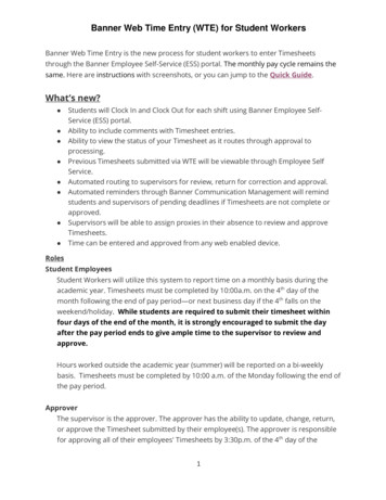
shift key down, and selecting more items,thus keeping them all selected.I also use tick marks, short lines, tohelp in aligning things like squaresor rectangles. An example was thecopy and pasting of the trianglesfor the spoke cut outs.Here I have copied, pasted andflipped the triangle horizontallyand then moved it to where I wantit to be. I have drawn two tick linesand have first selected thehorizontal rectangle in the cross,then holding the shift button, haveselcted the tick mark to the rightand then hit the ‘Top Alighnment’tool. This aligns the tick mark with the top of the rectangle. I do the same toalign the top tick mark by firstselecting the vertical rectangle,holding Shift and then selectingthe top tick mark and hitting the‘Align right’ tool.Now it’s just a matter of selectingthe right hand tick mark, holdingShift, then selecting the triangleand hitting the ‘Align bottom’tool. The triangle has now aligneditself on top of the rectangle andit’s just a matter of doing thesame with the top tick line andusing the ‘Align left’ tool.To save time you can now select bothtriangles, copy, paste and then flip vertically.While they are still both highlighted, movethem into position. Now I align the righthand tick mark with the bottom of thehorizontal rectangle and align both bottomtriangles with the ‘Top align’ tool. Instead ofnow re-aligning the top tick mark, I simplyhighlight the triangle above the one I want tomove and then align the bottom one with it,by selecting the ‘Left or Right align’ tooldepending which one you’re moving. QED.You can test the dxf file with a CADprogram like CNC USB Motion Controller 20178
and simulate the cutting of the gear. I have had many things made by usingeither laser cutting or water jet cutting, like brackets, wood templates, woodanimals for mosaic designs, motor bike engine overhaul stands etc. 20179
How to Draw a Clock Gear in Visio. By Mike MacLeod. Programs required: Forest Moons 'GearDxf' - free A9Tech 'A9Convertor' - free Visio, V3.0 - 2007 Step 1. Open Forest Moons 'GearDxf' and set the parameters, making sure that you have a dimension in the 'Bore hole diameter' box, then save the file to a folder