Transcription
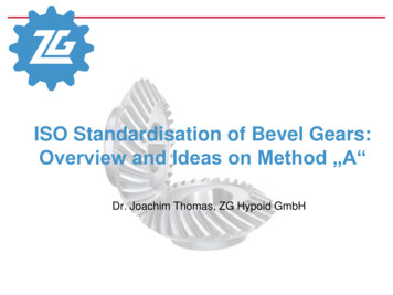
ISO Standardisation of Bevel Gears:Overview and Ideas on Method „A“Dr. Joachim Thomas, ZG Hypoid GmbH
Dr. J. Thomas09.02.2018Slide 2Content1. ISO Standardisation of Bevel Gear2. Calculation Methods B C3. Example Calculation4. Conclusions
Dr. J. Thomas09.02.2018Slide 3ISO1. ISO Standardisation of Bevel GearsISO/TC60/SC2: Gear Capacity Calc.International Standard OrganisationTC 60Technical Committee:GearsSekretariat: ANSIChairperson: Thomas MaiuriSC 1Sub Committee:Nomenclature & Worm GearingSekretariat: BSIChairperson : Dr. Paul BradleySC 2Sub Committee:Gear Capacity CalculationSekretariat: DINChairperson : Dr. Ralf Möllendorf
Dr. J. Thomas09.02.2018Slide 4WG 131. ISO Standardisation of Bevel GearsISO/TC60/SC2/WG13: Bevel GearsWorking Group:Bevel GearsChairperson: Dr. Joachim ThomasDelegates:USA:Claus Weyand, Amir Aboutaleb (AGMA)UK:N.N.Japan:Ryohei TakedaFinland:Jesse RontuSwitzerland:Jürg LanghartGermany:Dr. Ralf Hess, Rudolf Houben,Josef Pellkofer, N.N. (DIN / VDMA)
1. ISO Standardisation of Bevel GearsLoad Capacity Calc. of Bevel GearsDr. J. Thomas09.02.2018Slide 5DIN 3991 (1988)AGMA 2003 (A86)AGMA 2003 (B97)for calculation of nonoffset bevel gears onlyISO 10300 (2001)ISO 23509 (2004)FVA 411ISO 10300 (2014?)ISO TC60/SC2/WG13Geometrycalculation ofbevel andHypoid gearscalculation of bevel andHypoid gears
Dr. J. Thomas09.02.2018Slide 61. ISO Standardisation of Bevel GearsLoad Capacity Calc. of Bevel GearsAdditional standards resp. recommendations:DIN 3961ISO 1328Tolerances for bevel andHypoid gearsISO 17485 (2006)Technical Report: Designrecommendations for bevelgears.AGMA 2005ISO/TR 22489 (2011)ISO TC60/SC1/WG2 (Ad hoc: Bevel Gears)ISO TC60/SC2/WG13
ExamplesTribologyFatigueDr. J. Thomas09.02.2018Slide 71. ISO Standardisation of Bevel GearsLoad Capacity Calc. of Bevel GearsISO 10300-1 (2014)Introduction and general influence factorsISO 10300-2 (2014)Calculation of surface durability (pitting)ISO 10300-3 (2014)Calculation of tooth root strengthISO/TS 10300-4Flank fractureISO/TS 10300-20ScuffingISO/TS 10300-22MicropittingISO/TR 10300-30Examples to part 1 3ISO/TR 10300-32Scuffing examplesvalidin progressplaned
Dr. J. Thomas09.02.2018Slide 81. ISO Standardisation of Bevel GearsMethods within StandardMethod Athe most precise and high-grade calculation method, orproved load capacity on real parts, per example bymeasurements (of stresses).Method Bthe best (simplified) calculation methodMethod Ca more simplified calculation methodMethod D ISO 10300 contains methods B and for some factors method C. It always is a target, to advance the methods to come nearer to method A asgood as possible.It always is allowed to calculate even some individual factors according to ahigher method, if available. Of course there always is the difficulty, if such ahigher method is accepted by customers and business partners. Question: How near is Method B1 of ISO 10300 to Method A?
Dr. J. Thomas09.02.2018Slide 9Content1. ISO Standardisation of Bevel Gear2. Calculation Methods B C3. Example Calculation4. Conclusions
Dr. J. Thomas09.02.2018Slide 102. Calculation Methods B CSafety FactorsS H 1, 2 HP 1 , 2:Safety factor for contact stressσHP:Allowable contact stressσH:Contact stressMinimal safety factor of contact stressS F 1, 2 FP 1 , 2 S F , minF 1, 2SF:Safety factor of tooth root stressσFP:Allowable tooth root stressσF:Tooth root stressSF, min :, minH 1, 2SHSH, min : SHminimal safety factor of tooth root stress
2. Calculation Methods B CStressesDr. J. Thomas09.02.2018Slide 11Method B1F H lbmn ZE Z F 1,2 ZM B KA KV KH KH ZKersa)Method B1LSF vmtb v m mnc)b) Y Fa 1 , 2 Y Sa 1 , 2 Y Y BS Y LS Kb)a)a):Forces, Geometryb):(Geometrical) influence factorsc):Force factorsZK:bevel gear factor 0,85A KV KF KF b)Influence of load carrying face width and lengthwise crowning resp.
Dr. J. Thomas09.02.2018Slide 122. Calculation Methods B CZone of ActionZone of action (schematic)0) max. zone of action (without crowning)1) Example of a real zone of action2) square zone of action of DIN 39913) elliptical zone of action AGMA & ISO 10300 (01)4) rhomboid zone of action acc. FVA 411ISO 10300 (2014):Method B1 acc. 4); width of contact pattern bTB depending on „effective“ face width If real width of contact pattern is not known, typically 0.85 b can be taken.This is not a specification within the standard, just a recommendation. In reality with of contact pattern is depending on lengthwise crowning and is different forevery different load case.
Dr. J. Thomas09.02.2018Slide 132. Calculation Methods B CForce FactorsKA KV KHβ KHαfor surface durability (pitting)KA KV KF KF for tooth root strengthKA: Application FactorKV: Dynamic FactorKH , KF : Face Load FactorsKH , KF : Transverse Load Factors
Dr. J. Thomas09.02.2018Slide 142. Calculation Methods B CFace Load Factor KH The Face Load Factor KH considers uneven load distribution on the flank.Definition:KwmH w maxwmdecisive calculation pointwmaxwmax: maximum line loadwm: mean line load, related to length of contact line
Dr. J. Thomas09.02.2018Slide 152. Calculation Methods B CFace Load Factor KH Within ISO 10300 only a Method C is available for face load factors, but there is ahint, that a Method B could be an examination by Loaded Tooth Contact Analysis(LTCA).Method C: KHß-C 1,5 KHß-be crowning:withoutcrowningwith crowning shaft deviations caused by mounting conditions (arrangement of bearings):
Dr. J. Thomas09.02.2018Slide 162. Calculation Methods B CMounting Factor KH beThe Mounting Factor KHb-be considers displacement of gear and pinion under loadcaused by the arrangement of bearingsVerification of contactpatternMounting conditions of pinion and gearboth straddlemountedone cantilever one straddle mountedboth cantilevermountedFor each gear set in its carrierunder full load1.001.001.00For each gear set under lighttest load1.051.101.25For a sample gear set andestimated for full load1.201.321.50Contact pattern is checked:Note: Based on optimum tooth contact pattern under maximum operating loadas evidenced by results of a deflection test on the gears in their respective mountings.Often taken value for calculation acc. ISO 10300:KHß-C 1,5 1,1 1,65
Dr. J. Thomas09.02.2018Slide 172. Calculation Methods B CFace Load Factor KF The Face Load Factor KF considers uneven stress distribution on the tooth root.Definition:σmaxσmσFmax: maximum tooth root stressKF Y BS F max FmσFm: mean tooth root stress
Dr. J. Thomas09.02.2018Slide 182. Calculation Methods B CFace Load Factor KF Within ISO 10300 only a Method C is available for face load factors, but there is ahint, that a Method B could be an examination by Loaded Tooth Contact Analysis(LTCA).Method C: KFß-C KHß-C / KF0with KF0: Lengthwise curvature factor“The lengthwise curvature factor KF0 considers the contact pattern shift under differentloads which is smallest, if the lengthwise tooth curvature at the mean pointcorresponds to that of an involute curve. This effect is well known and depends onthe cutter radius rc0 and the spiral angle βm2.” (Source: ISO 10300-1 (2014)).1,00 KF0 1,15: That means, that maximum effect of small tool radius is 15%.
Dr. J. Thomas09.02.2018Slide 19Content1. ISO Standardisation of Bevel Gear2. Calculation Methods B C3. Example Calculation4. Conclusions
Dr. J. Thomas09.02.2018Slide 203. Example CalculationGear and Load Data
Dr. J. Thomas09.02.2018Slide 213. Example CalculationISO10300 Method B(C)Input for first calculation acc. to ISO 10300 (Method B1):Rel. contact width:beff 0,85 bMounting factor:KHß-be 1,1Results:Method C KHß-C 1,65Method C KFß-C 1,435 with KF0 1,15
Dr. J. Thomas09.02.2018Slide 22ISO (Meth. B/C):3. Example CalculationBecal*) LTCA – comp. to ISO (Method B/C)σH ISO / ZK 2796,86 MPaPinionISO (Meth. B/C):*)σF1 ISO 1296,36 MPaGearσF2 ISO 1412,79 MPaBecal is a software tool by FVA e.V. (Forschungsvereinigung Antriebstechnik – Research Association for Drive Technology)
Dr. J. Thomas09.02.2018Slide 233. Example CalculationFace Load Factors Method BLoad distributionbbeff / b 0,90beffKHß wmax / wm 1,49PinionKFß1 YBS σF1max / σF1m 3,44GearKFß2 YBS σF2max / σF2m 2,99
Dr. J. Thomas09.02.2018Slide 243. Example CalculationISO10300 Methode B(B)Input for second calculation acc. ISO 10300:Rel. contact width:beff 0,90 bFace Load factors (Method B):KHß-B 1,49KFß1-B 1,67 KFß2-B 1,45with YBS 2,06Results:
Dr. J. Thomas09.02.2018Slide 25ISO (Meth. B/B):3. Example CalculationBecal*) LTCA – comp. to ISO (Method B/B)σH ISO / ZK 2534,09 MPaPinionISO (Meth. B/B):*)σF1 ISO 1362,76 MPaGearσF2 ISO 1315,29 MPaBecal is a software tool by FVA e.V. (Forschungsvereinigung Antriebstechnik – Research Association for Drive Technology)
Dr. J. Thomas09.02.2018Slide 26Content1. ISO Standardisation of Bevel Gear2. Calculation Methods B C3. Example Calculation4. Conclusions
Dr. J. Thomas09.02.2018Slide 27 4. ConclusionsWithin the series of standards ISO10300 for the load carrying capacity calculation ofbevel gears actually are covered standards for the tooth flank (pitting) and toothroot capacity. There are available specifications for scuffing calculation as well astechnical reports for sample calculations. Additional parts will be addedcontinuously. The actual standards include quite rough influences of lengthwise crowning only(Method C). This lead to obvious differences in comparison to results according tosuperior calculation methods, like loaded tooth contact analysis (LTCA). As soon as results according to LTCA (Method B) are introduced into ISO10300, thedifferences in final results are (negligible?) low and a proof of load carryingcapacity according ISO10300 is possible. If LTCA calculation software packages have been proved by measurements on realbevel gears, these methods actually are most near to reality (Method A) accordingto actual state of knowledge.
Dr. J. Thomas09.02.2018Slide 28Thank you for yourattention!
Additional standards resp. recommendations: DIN 3961 ISO 1328 ISO TC60/SC1/WG2 (Ad hoc: Bevel Gears) Dr. J. Thomas Slide 7 09.02.2018 1. ISO Standardisation of Bevel Gears Load Capacity Calc. of Bevel Gears Examples to part 1 3 Scuffing valid ISO 10300-1 (2014) Micropitting Flank fracture ISO 10300-2 (2014) ISO 10300-3 (2014) ISO/TS 10300-20 ISO/TS 10300-22 ISO/TS 10300-4 Introduction