Transcription
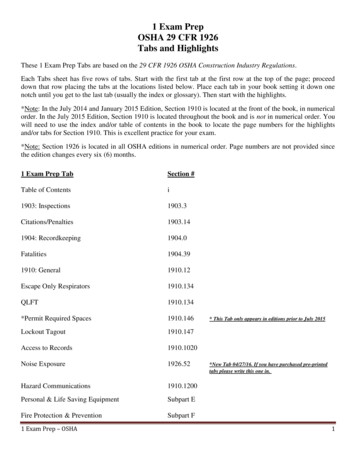
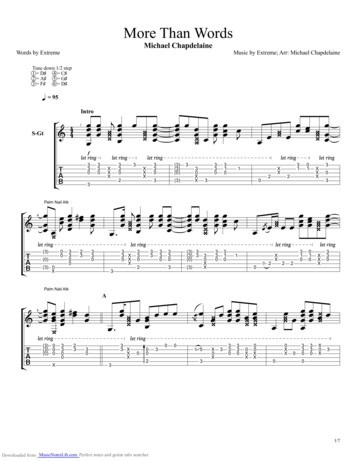
SD-13-4767 Bendix TABS-6 Standard and Premium Trailer ABS ModulesElectronicControl Unit(ECU) Cover(Sealed)ECU Pin-out Label(See Page 33)3/8" NPT ControlPort withIntegral FilterThe ECU ConnectorVaries for Standard andPremium - See ChartECU ConnectorCover(Removable)IntegratedModulatorRelay ValveWheel SpeedSensorConnectorsThe Standard TABS-6Module uses afive (5)-Pin ConnectorThrough-holesfor Frame(Chassis)Mounting3/4" NPTSupply PortFour (4) 3/8" NPTDelivery Ports(To Brake Chambers)Part NumberLabel(See Page 33)To Remove Cover SlideLock TabThe Premium TABS-6Module uses an18-Pin ConnectorFIGURE 1 - BEndIx TABS-6 STAndARd And PREmIUm mOdULESINTRODUCTIONThe Bendix TABS-6 module is an integrated trailer ABScontroller and modulator for air-braked heavy-duty trailers, semitrailers and dollies. The module acts as a relay valve duringnormal braking, but during ABS events, it will intervene to helpimprove stability. All modules include an Electronic Control Unit(ECU) and Modulator Relay Valve (MRV) which are integratedinto a single self-contained 2S/1M (two-sensor, one modulator)trailer ABS unit. The Premium Bendix TABS-6 module is autoconfigurable to control more sensors and modulators (up to4S/3M) from its default 2S/1M. Bendix TABS-6 modules also feature: Internal electrical connections to the primary MRV,eliminating the need for external pigtail harnesses. Optional mounting to the service reservoir or to the chassis,without additional brackets. Blink code diagnostics and support for advanced diagnostictools. Support for Power Line Carrier (PLC) communication to thetowing vehicle. A pressure equalizing valve in the sealed ECU housing togive improved protection from water, etc. A locking dust cover to provide additional electricalconnector and cable protection. A serviceable nylon filter to help prevent foreign materialfrom entering the control port.TABLE OF CONTENTSPAGEIntroduction . . . . . . . . . . . . . . . . . . . . . . . . . . . . . . . .1General Safety Guidelines . . . . . . . . . . . . . . . . . . . .2Components . . . . . . . . . . . . . . . . . . . . . . . . . . . . . . .2Mounting Configurations. . . . . . . . . . . . . . . . . . . . . .3PLC Communications . . . . . . . . . . . . . . . . . . . . . . . .3Wiring Harness (Pigtail) . . . . . . . . . . . . . . . . . . . . 3-4Power and Ground . . . . . . . . . . . . . . . . . . . . . . . . . .4ABS Indicator Lamp . . . . . . . . . . . . . . . . . . . . . . . . .5Wheel Speed Sensors . . . . . . . . . . . . . . . . . . . . . 5-6Bendix BR9235 ABS Modulator Valves. . . . . . . . . 6J1708/J1587 Diagnostic Link . . . . . . . . . . . . . . . . . .7Auxiliary I/O . . . . . . . . . . . . . . . . . . . . . . . . . . . . . . .7Bendix Flex ABS Program . . . . . . . . . . . . . . . . . .7Customer Scratch Pad . . . . . . . . . . . . . . . . . . . . . . .7Power-up Sequence . . . . . . . . . . . . . . . . . . . . . . . 7-8ABS Operation . . . . . . . . . . . . . . . . . . . . . . . . . . . . .8Auto-Configuration . . . . . . . . . . . . . . . . . . . . . . . . . .8Odometer Function . . . . . . . . . . . . . . . . . . . . . . . . . .8Non-standard Tire Size . . . . . . . . . . . . . . . . . . . . . . .9Diagnostic Trouble Code Detection . . . . . . . . . . . . . 9Partial ABS Shutdown. . . . . . . . . . . . . . . . . . . . . . .10Blink Code Diagnostics. . . . . . . . . . . . . . . . . . . . . .10Diagnostic Trouble Codes (DTCs) . . . . . . . . . . 11-13Using Hand-Held or PC-Based Diagnostics . . . . . . 14Bendix ABS Diagnostic Tools . . . . . . . . . . . . . . 14-15Contacting Bendix. . . . . . . . . . . . . . . . . . . . . . . . . .15Servicing the Bendix TABS-6 Module. . . . . . . . . . . 16Service Replacement of Other ABS Controllers . . . 16Leakage and Operational Tests . . . . . . . . . . . . . . . 17ABS Wiring . . . . . . . . . . . . . . . . . . . . . . . . . . . . . . .18Troubleshooting . . . . . . . . . . . . . . . . . . . . . . . . 19-321
COMPONENTSInstallations of the Bendix TABS-6 module typically utilize the following components: Two or four Bendix WS-24 wheel speedsensors (depending on the configuration).Each sensor is installed with a BendixSensor Clamping Sleeve. See page 5. A trailer-mounted ABS indicator lamp.See page 5. Zero, one, or two Bendix BR9235 Pressure Modulator Valves (dependingon configuration). See page 6. Pigtail wiring harness(es) as needed.See page 4.GENERAL SAFETy GUIDELINESWARNING! PLEASE READ AND FOLLOW THESE INSTRUCTIONSTO AVOID PERSONAL INJURy OR DEATH:When working on or around a vehicle, the following guidelines should be observed AT ALL TIMES: Park the vehicle on a level surface, apply theparking brakes and always block the wheels.Always wear personal protection equipment. Stop the engine and remove the ignition keywhen working under or around the vehicle.When working in the engine compartment,the engine should be shut off and the ignitionkey should be removed. Where circumstancesrequire that the engine be in operation, ExTREMECAUTION should be used to prevent personalinjury resulting from contact with moving,rotating, leaking, heated or electrically-chargedcomponents. Do not attempt to install, remove, disassembleor assemble a component until you have read,and thoroughly understand, the recommendedprocedures. Use only the proper tools andobserve all precautions pertaining to use of thosetools. If the work is being performed on the vehicle’sair brake system, or any auxiliary pressurized airsystems, make certain to drain the air pressurefrom all reservoirs before beginning ANy workon the vehicle. If the vehicle is equipped with aBendix AD-IS air dryer system, a Bendix DRM dryer reservoir module, or a Bendix AD-9si airdryer, be sure to drain the purge reservoir. F o l l o w i n g t h e v e h i c l e m a n u f a c t u r e r ’srecommended procedures, deactivate theelectrical system in a manner that safely removesall electrical power from the vehicle. Never exceed manufacturer’s recommendedpressures. Never connect or disconnect a hose or linecontaining pressure; it may whip and/or causehazardous airborne dust and dirt particles. Weareye protection. Slowly open connections withcare, and verify that no pressure is present. Neverremove a component or plug unless you arecertain all system pressure has been depleted. Use only genuine Bendix brand replacementparts, components and kits. Replacementhardware, tubing, hose, fittings, wiring, etc. mustbe of equivalent size, type and strength as originalequipment and be designed specifically for suchapplications and systems. Components with stripped threads or damagedparts should be replaced rather than repaired.Do not attempt repairs requiring machining orwelding unless specifically stated and approvedby the vehicle and component manufacturer. Prior to returning the vehicle to service, makecertain all components and systems are restoredto their proper operating condition. For vehicles with Automatic Traction Control(ATC), the ATC function must be disabled (ATCindicator lamp should be ON) prior to performingany vehicle maintenance where one or morewheels on a drive axle are lifted off the groundand moving. The power MUST be temporarily disconnectedfrom the radar sensor whenever any tests USINGA DyNAMOMETER are conducted on a vehicleequipped with a Bendix Wingman system. you should consult the vehicle manufacturer's operating and service manuals, and any related literature,in conjunction with the Guidelines above.Disconnect the electrical connectors from the ABS/TRSP Controller before welding on the trailer.2Dielectric grease should be applied to electricalconnectors to help protect against moisture intrusion.
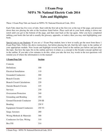
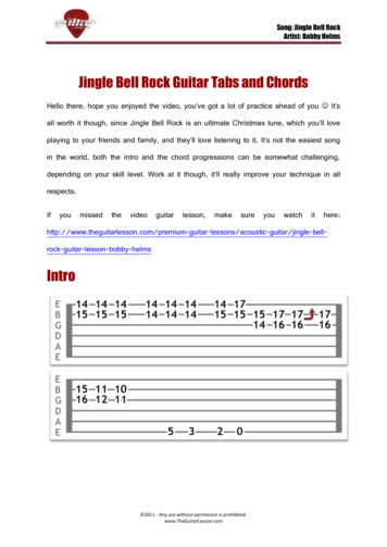
MOUNTING CONFIGURATIONSFor all NPT fittings use of a thread sealant isrequired. For NPTF fittings the use of a threadsealant is recommended, this can be a pre-appliedor a hand applied sealant product (with PTFE).When using a hand-applied sealant, use cautionso as not to over apply. Always follow the fittingmanufacturer’s pre-applied or hand-applied threadsealant recommendations. Use of PTFE tape is notapproved and will void the Bendix ABS/TRSP valvewarranty.FIGURE 2 - POWER LInE WITHOUT PLC SIGnALTank (Nipple) MountThe Bendix TABS-6 modules can be tank-mounted usinga schedule 80 (heavy gauge steel) 3/4" NPT nipple directlybetween the trailer supply tank and the module's supplyport. A tank with a reinforced port must be used.Frame (Chassis) MountThe Bendix TABS-6 module provides through-holes forframe mounting directly to the trailer frame rail or crossmember. It is recommended to use two Grade 5 3/8-16bolts, typical length 5", torqued to 180-220 in-lbs.POWER LINE CARRIER (PLC)COMMUNICATIONSSince March 1, 2001, all new towed vehicles transmit asignal over the power line to an in-cab trailer ABS IndicatorLamp. The signal, using a heavy vehicle industry standardknown as “PLC4Trucks,” is typically broadcast by thetrailer ABS Electronic Control Unit (ECU) over the bluewire (ignition/power line) of the SAE J560 connector. SeeFigures 2 and 3.FIGURE 3 - POWER LInE WITH PLC SIGnALSuggested oscilloscope settings are (AC coupling, 1 volt/div, 100 µsec/div). The signal should be measured onpin seven (7) of the J560 connector at the nose of the trailer.PIGTAIL WIRING HARNESSESBendix TABS-6 modules support PLC communications inaccordance with SAE J2497.Several pigtail wire harnesses are available to connectthe Bendix TABS-6 module with ABS and other trailersystem components. See Figure 4. Pigtail harness areweather sealed at the connector interface and are clearlylabeled for proper installation. Because of the over-moldeddesign of the TABS-6 module wiring harnesses, Bendixrecommends that the complete harness be replaced ifdamage or corrosion occurs.Identifying and Measuring the PLC SignalThe following connector options may be present:A Bendix TABS-6 module will continuously broadcast PLCmessages that indicate trailer ABS status. At power-upor during a trailer ABS Diagnostic Trouble Code (DTC)condition, the Bendix TABS-6 module will signal thetractor ABS unit to illuminate the dash-mounted trailer ABSindicator lamp.Modulator 2 (MOD2), Modulator 3 (MOD3), auxiliary,diagnostic, and additional axle wheel speed sensors.Diagnostic tools are available that detect the presenceof a PLC signal and perform further system diagnosticsdirectly on the power line. For more information on thesediagnostic tools, contact Bendix or refer to your localauthorized Bendix dealer or distributor.An oscilloscope can also be used to verify the presenceand strength of a PLC signal on the power line. The PLCsignal is an amplitude and frequency modulated signal.Depending on the load on the power line, the amplitudeof the PLC signal can range from 5.0 mV p-p to 7.0 V p-p.Note: All Bendix TABS-6 modules include the two primarywheel speed sensor connections and therefore these areseparate from the pigtail harness.ECU ConnectorsStandard Bendix TABS-6 module ECU connectors usea TTMA 97-99 5-pin Delphi Weather Pack connector forbrake light power, constant power, ground, and the trailermounted ABS indicator lamp.Premium Bendix TABS-6 module ECU connectors use an18-pin Deutsch DT series connector for the same functionas above, plus additional modulators, wheel speed sensorsand auxiliary I/O’s.3
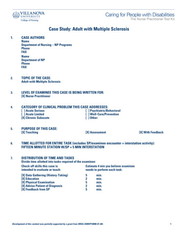
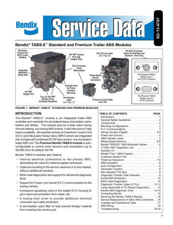
Power/ABS Indicator Lamp ConnectorDiagnostic ConnectorThe Bendix TABS-6 module pigtail uses a TTMA RP 9799 five (5)-pin Delphi Weather Pack connector for brakelight power, constant power, ground and the trailer-mountedABS indicator lamp.Premium Bendix TABS-6 module pigtail harnesses providea four (4)-pin diagnostic connection for a diagnostic toolto monitor Electronic Control Unit (ECU) ignition power,ground and data information. Remote diagnostic cablesare available from Bendix to provide a standard J1708/J1587 diagnostic port at the side of the trailer.The Power/ABS indicator lamp lead of the pigtail harnessis available in several lengths to satisfy most installationrequirements (e.g. slider axles).Wheel Speed Sensor ConnectorsTwo (2)-pin connectors are provided for additional wheelspeed sensors for 4S ABS applications. These connectorsare labeled Additional Sensor Left (SAL), and AdditionalSensor Right (SAR). Extension cables are available invarious lengths from Bendix.ABS Modulator ConnectorsOn Premium Bendix TABS-6 module pigtail harnesses, oneor two modulator connectors are provided for trailers usingtwo or three modulators. These three (3)-pin connectorsare labeled MOD2 and MOD3. (Note: MOD1 designatesthe internal modulator of the Bendix TABS-6 module).Remote modulator harnesses are available in many lengthsto satisfy most installation requirements.5-Pin Power andIndicatorLamp (POWER/WL)Auxiliary I/O ConnectorAn optional auxiliary connector provides a connection to theBendix TABS-6 module auxiliary I/O ECU pins. PremiumECU pigtails provides an option for up to six auxiliary I/O’s.POWER AND GROUNDTrailer electrical power is supplied to the Bendix TABS-6module from the ignition and brake light circuits. SeeCharts 1 and 2 for output values and pin locations.Function ModeValueOperating Range8.0 to 16.0 VDCECU Active135 mA @ 12 VDCABS Active (1 Modulator)3.7 A @ 12 VDCABS Active (2 Modulators)5.2 A @ 12 VDCCHART 1 – vALUES FOR OUTPUTS2-Pin AdditionalWheel SpeedSensorConnectors(SAL & SAR)18-Pin ECU Connector3-Pin Modulator 2(MOD2)Premium Pigtail Harness(4S/2M with diagnostic)4-Pin DiagnosticAuxiliary(Optional)3-Pin Modulator 3(MOD3) (Optional)5XXX.BA5XXX.EDTo BR9235 ABS ModulatorRelay ValveTo Bendix TABS-6 Module PigtailModulator Extension HarnessTo DiagnosticTool5-Pin Power andIndicator Lamp(POWER/WL)Power Extension Harness5-Pin ECUConnectorTo Bendix TABS-6Module Pigtail5XXX.Diagnostic Tool HarnessTo ECU or PigtailFIGURE 4 - ExAmPLES OF PIGTAIL WIRE HARnESSES AvAILABLE4Wheel Speed SensorExtension HarnessTo WS-24 WheelSpeed SensorC
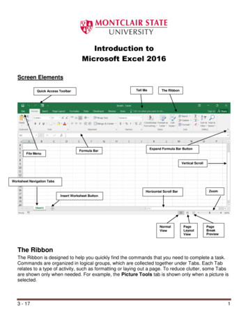
CircuitIgnition PowerPLC (Blue Wire)Brake nn.18-PinECUConn.7BB6changes. (The default setting expects a 100-tooth tone ringto be used.) Vehicle axle and ABS control configurationsdetermine if two or four wheel speed sensors are required.See page 19 for electrical system schematics showingwheel speed sensor connector pin locations.12A proper sensor installation is critical to correct ABSoperation.4AA(Red Wire)Ground(White Wire)1EE18N/ADD5Indicator Lamp(White/GreenWire)CHART 2 – POWER And GROUndTypically, the WS-24 sensor is installed in mounting blocksthat are welded to the axle housing. WS-24 wheel speedsensors are protected by a stainless steel sheath. Theyare designed to be used with beryllium copper clampingsleeves (sometimes referred to as a “retainer bushing”,“friction sleeve” or “clip”) (See Figure 6). The clampingsleeve provides a friction fit between the mounting blockbore and the WS-24 sensor.SensorClampingSleeve90 SpeedSensorsLogo Stampedinto SleeveFIGURE 5 - TRAILER-mOUnTEd ABS IndICATOR LAmPABS INDICATOR LAMPTrailer-mounted LampThe Bendix TABS-6 module controls an ABS indicatorlamp to show the trailer ABS status. With power supplied bythe towing vehicle, the module illuminates the ABS indicatorlamp by providing a 12.0 VDC signal. (The other side ofthe lamp is grounded.) The ABS indicator lamp output usesPin D of the five (5)-pin Standard module connector, andPin 5 of the 18-pin Premium module connector.Dash-mounted Lamp (PLC Controlled)Bendix TABS-6 modules use SAE J2497 standards tosupport Power Line Carrier (PLC) communication. TheBendix TABS-6 module transmits a signal over the powerline to the towing vehicle. This information is used bytowing vehicle’s ABS controller to know when to illuminatethe trailer ABS indicator lamp mounted on the dash.The status of the trailer ABS is transmitted over the ignitionpower wire (blue wire of the J560 connector), Pin B of thefive (5)-pin Standard module connector, or Pin 6 of the18-pin Premium module connector.BENDIx WS-24 WHEEL SPEED SENSORSWheel speed data is provided to the Bendix TABS-6 modulefrom the WS-24 wheel speed sensors (see Figure 6).Vehicles have an exciter ring (or “tone ring”) as part of thewheel assembly, and as the wheel turns, the teeth of theexciter ring pass the wheel speed sensor, generating an ACsignal. The Bendix TABS-6 module receives the AC signal,which varies in voltage and frequency as the wheel speedStraight SpeedSensorsFIGURE 6 - BEndIx WS-24 WHEEL SPEEd SEnSORS1. For increased corrosion protection we recommendthat a high-temperature rated silicon- or lithium-basedgrease be applied to the interior of the mounting block,the sensor, and to a new clamping sleeve.2. Install the new clamping sleeve fully into the block,with the retaining tabs toward the inside of the vehicle.Please note that WS-24 wheel speed sensors mustuse the correct clamping sleeve to avoid problemsassociated with reduced retention force, such as sensormovement and resulting ABS trouble codes.Use of cable ties/tie wraps to attach wheel speedsensor leads to rubber hoses/jounce lines is notapproved. The hose may expand during brakingdue to air pressure and the cable tie may not, so theconductor material/insulation of the speed sensorextensions may be damaged. Bendix insteadrecommends only open-ended clips be used to holdsensor leads to jounce lines.3. Gently push (DO NOT STRIKE) the sensor into themounting block hole until it bottoms out on the face ofthe tone ring. Secure the cable lead wire to the knuckle/axle housing three to six (3-6) inches from the sensor.See Figure 7.5
SensorSecureTo AxleSecure ToService HoseSensor MountingBlockUse open-endedcable clips whensecuring sensorharnesses toservice hoses.Bendix BR9235 modulator relay valves (MRV) arerequired when additional modulator relay valves areneeded for multichannel brake systems (e.g. 2S/2M, 4S/3MABS configurations).The MRV is an electro-pneumatic control valve and is thelast valve that air passes through on the way to the brakechambers. The normally-open hold solenoid and normallyclosed exhaust solenoid are activated to precisely modifythe brake pressure on command. During normal braking,the Bendix BR9235 MRV functions as a standard relayvalve. As brakes are applied or released by the driver, thecontrol signal from the tractor foot valve causes the BendixBR9235 MRV to apply proportional pressure to the trailerbrake chambers.Stress LoopTo TABS-6Service HoseSpeed SensorLead WireBENDIx BR9235 ABSMODULATOR RELAy VALVESThe Bendix BR9235 MRV is available in both tank andbracket mounting styles. See Figure 8.3-Pin ModulatorSolenoidConnectorSecureTo Axle3/8" NPT ControlPort with IntegralFilterFIGURE 7 - SEnSOR LEAd ROUTInG And SECURInG4. Apply a moderate amount of dielectric non-conductivegrease to both the sensor connector and harnessconnector.5. Engage the connectors, and push together until thelock tab snaps into place.NOTE: It is important for the wheel bearings to beadjusted per the manufacturer's recommendations.The friction fit allows the Bendix WS-24 sensor to slideback and forth under force but to retain its position whenthe force is removed. When the Bendix WS-24 sensor isinserted all the way into the mounting block and the wheelis installed on the axle, the hub exciter contacts the sensor,which pushes the sensor back. Also, normal bearingplay will “bump” the sensor away from the exciter. Thecombination of these two actions will establish a runningclearance or air gap between the sensor and exciter.Excessive wheel end play can result in diagnostic troublecodes in cases where the sensor is pushed too far awayfrom the tone ring.Use open-ended cable clips when securing sensorharnesses to service hoses.6Four 3/8" NPT Delivery Ports(to Brake Chambers)FIGURE 8 - BEndIx BR9235 mOdULATOR RELAy vALvECRACK PRESSUREBendix TABS-6 Standard modules with a componentindex of S009 have no spring and are rated at a crackpressure of 3 0.5 psi.Bendix TABS-6 Standard modules with a component indexof S010 and higher have a spring and are rated at a crackpressure of 4.5 0.5 psi.Modulator Relay Valve (MRV) Crack PressureThe Bendix TABS-6 ABS modulator relay valves areavailable with nominal crack pressure of 4.5 0.5 psi.Previous models of Bendix TABS-6 modulator relayvalves came with a nominal crack pressure of 3.0 0.5psi. Installation drawings are available that can provideinformation on which version you have.
Tank (Nipple) MountedThe Bendix BR9235 Modulator Relay Valve (MRV) canbe tank-mounted using a schedule 80 (heavy gauge steel)3/4" NPT nipple directly between the trailer supply tank andthe supply port. A tank with a reinforced port must be used.Bracket (Chassis) MountedThe Bendix BR9235 MRV provides an option with abracket for frame mounting directly to the trailer frame railor crossmember. It is recommended to use two Grade 5,3/8-16 bolts, torqued to 180 – 220 in-lbs.J1708/J1587 DIAGNOSTIC LINKThe Premium Bendix TABS-6 module provides a J1708/J1587 diagnostic link with data and power to communicatewith the vehicle and various diagnostic tools. Diagnostics,testing, configuration, data transfer and other functions canbe performed using this link. Diagnostic tools such as theMPSI Pro-Link device and Bendix ACom DiagnosticSoftware (version 6.5 and higher) support the BendixTABS-6 module.Ignition power must be provided to the Bendix TABS-6module for the diagnostic link to be active.AUxILIARy I/OThe Standard module provides for one auxiliary I/Ofunction.The Premium module provides for up to five auxiliaryfunctions and one additional ground. See Chart 3, below.Bendix ACom Diagnostic Software (version 6.5 andhigher) supports the configuration of the Bendix TABS-6module auxiliary I/O’s. BENDIx FLEx ABS PROGRAMA Bendix Flex ABS program uses Auxiliary DesignLanguage (ADL) to allow customized auxiliary functions tobe carried out by the Bendix TABS-6 module. Functionsdeveloped in the Bendix Flex ABS program may bedownloaded at the production line or in the field to controlnon-braking functions of the trailer.For example, a Bendix Flex ABS program can potentiallycommunicate the status of: tire inflation and/or temperature;reefer temperature; load presence; slider-pin position; liftaxle position; proximity/reverse alarm; and vehicle weight.The Bendix Flex ABS program can monitor the auxiliary I / Osand/or the SAE J1587 diagnostics and SAE J2497 PLC datalinks. Contact your Bendix Account Manager to discuss aBendix Flex ABS program for your vehicle(s).CUSTOMER SCRATCH PADThe Bendix TABS-6 module has a Customer Scratch Padfeature which allows the customer, or end-user, to store upto 756 bytes of information. This information can then beread using the Bendix ACom Diagnostic Software (version6.5 and higher).If additional scratch pad space is needed, this storagespace can be expanded to 1K (1,008 bytes total of data).Contact Bendix for further details.POWER-UP SEQUENCEAt power-up, the Bendix TABS-6 module performs a seriesof self-checks that can assist a technician to determine theABS system status and configuration.Trailer ABS Indicator LampAt power-up without detected Diagnostic Trouble Codes(DTCs), the trailer ABS indicator lamp will turn on for 2.5seconds as a bulb check and then turn off. See Figure 8.If a PLC-ready towing vehicle and trailer are powered at thesame time, the Bendix TABS-6 module will also trigger abulb check on the dash-mounted trailer ABS indicator lamp.Modulator Chuff Test at Power-UpAt power-up, the Bendix TABS-6 module activates amodulator chuff test. This electrical and pneumatic ABSmodulator test can help the technician identify problemswith modulator installations and/or wiring.With brake pressure applied, a properly installed modulatorwill cause five (5) rapid audible chuffs of air pressure. Ifadditional modulators are installed, the Bendix TABS-6module activates five (5) chuffs at the internal modulator(MOD1) then five (5) chuffs for each additional modulatorin sequence (e.g. MOD1, then MOD2, and then MOD3).The chuff sequence is then repeated.If the modulator is wired incorrectly, the modulator willonly produce one chuff, or no chuff at all. If an issue isdetected during the modulator chuff test, compare themodulator wiring and plumbing to the Bendix TABS-6module’s electrical system schematic (see page 19) andmake repairs.NameECUECU Pin Auxiliary FunctionsDefault FunctionAUX1Premium16 High-Side Driver or Digital InputModulator 3 (MOD3) Hold SolenoidAUX2Premium10 High-Side Driver or Digital InputModulator 3 (MOD3) Release SolenoidAUX3Premium15 High-Side Driver or Digital InputModulator 2 (MOD2) Hold SolenoidAUX4Premium9 High-Side Driver or Digital InputModulator 2 (MOD2) Release SolenoidAUX5Premium4 Low-Side Driver or Analog InputModulator 3 (MOD3) CommonAUX6Premium2 High-Side Driver or Digital InputJ1587 Diagnostic PowerCHART 3 – AUxILIARy I/OS And dEFAULT FUnCTIOnS7
ABS SystemStatus IndicatorsPowerApplication0.5 1.5 2.0 2.5 3.0 (sec.)Trailer-mounted ABS ONIndicator Lamp OFFDash-mounted Trailer ONABS Indicator LampOFF(PLC Detected)*Dash-mounted Trailer ONABS Indicator Lamp(PLC Not Detected) OFF*Some vehicle manufacturers may illuminate the trailer ABSindicator lamp at power-up regardless of whether a PLCsignal is detected from the trailer or not. Consult the vehiclemanufacturer’s documentation for more details.FIGURE 8 - TRAILER ABS LAmP START-UP SEqUEnCEABS OPERATIONThe Bendix TABS-6 module uses wheel speed sensors,modulator relay valves and an Electronic Control Unit(ECU) to control trailer wheels by axle or by side. Bymonitoring individual wheel turning motion during braking,and adjusting or pulsing the brake pressure at each wheel,the Bendix TABS-6 module is able to optimize slip betweenthe tires and the road surface. When excessive wheel slip,or wheel lock-up, is detected, the ECU will activate thePressure Modulator Valves to modulate braking pressureat the wheel ends. The ECU is able to pump the brakeson individual wheels (or pairs of wheels), independently,and with greater speed and accuracy than a driver.Axle ControlBendix TABS-6 module axle control uses a single modulatorrelay valve to control wheels on both sides of a given axleor axles. In the case of an ABS event on road surfaceswith poor traction (worn, slippery, or loose gravel roads)or areas of poor traction, (e.g. asphalt road surfaces withpatches of ice), axle control will maintain the wheel that isnot slipping at just under the speed that will lock the wheel.Temporary periods of wheel lock are permitted on the otherwheel that is experiencing slippage.Axle control should not be used on 5th wheel dollies orsteerable axles. When braking on even surfaces, anaxle-control system will perform similar to a side control,two-modulator system. Axle control is available in 2S/1M,2S/2M and 4S/2M installations, and for Modulator 3(MOD3) in a 4S/3M installation.dolly axle control will control the low coefficient (slipping)wheel just under the lock limit. Vehicle stability is assistedby not allowing the high coefficient wheel (where tractionis still being maintained) to sustain wheel lock.When braking on even surfaces, a dolly axle control systemwill perform similar to side control or axle control system.Dolly axle control is only available in 2S/1M installations.Side ControlThe Bendix TABS-6 module uses a single modulator relayvalve to control one or more wheels on a given vehicleside. In the case of an unbalanced braking surface, theside control will individually control wheels on each sidejust under the point where they would lock up.Side control is available in 2S/2M and 4S/2M installations,and for the internal modulator (MOD1) and Modulator 2(MOD2) in the 4S/3M installation.Normal BrakingDuring normal braking, the Bendix TABS-6 modulefunctions as a standard relay valve. If the ECU does notdetect excessive wheel slip, it will not activate ABS control,and the vehicle stops with normal braking.AUTO-CONFIGURATIONThe Standard Bendix TABS-6 module is available onlyin the 2S/1M ABS configuration and does not use autoconfiguration.For the Premium Bendix TABS-6 module, the default ABSconfiguration is 2S/1M. At power-up, if a Premium ECUdetects additional sensors and modulators it will performan auto-configuration. Auto-configuration only adjustsupward (e.g. 2S/2M Side to a 4S/2M Side configuration).Additional detected components that do not conform toa legitimate configuration will generate the appropriateDiagnostic Trouble Code (DTCs).Note: If the vehicle begins moving before the newconfiguration has been accepted, the reconfigurationwill not take place at this time.ODOMETER FUNCTIONOdometerThe Bendix TABS-6 module includes an odometer functionto provide a means of storing the accumulated mileageof the vehicle. The mileage is computed by utilizinginformation calculated from the vehicle wheel speeds.Dolly-Axle Control (Select Low)This feature is accurate to within 0.62 miles per power-upand will typically store mileage up to 1,000,000 miles. Themileage can be displayed using PC diagnostics or throughblink codes.Bendix TABS-6 module dolly-axle control uses a singleABS modulator valve to control wheels from both sides ofa given axle or axles. In the case of an unbalanced brakingsurface, (e.g. asphalt road surfaces with patches of ice),Whenever the module is towed using a pre-1997 tractor— one that is stop-lamp-powered (SLP) — the electronicodometer does not function, and the mileage can beconsidered out-of-calibration.8
Trip CounterThe module provides a counter to record the trip mileage.The feature is accessed through PC or hand-helddiagnostic tools.MISCELLANEOUS MAINTENANCEGLAD HAND MAINTENANCE NEVER POUR ANy LIQUIDS (alcohol, anti-freeze,additives, etc.) into the glad hands. Liquids maycause the o-rings and seals to swell, may resultin lubrication loss and leave harmful residues.diagnostic tools. If configured, the Bendix TABS-6 modulecan flash the indicator lamp when the vehicle is at standstillto indicate
a TTMA 97-99 5-pin Delphi Weather Pack connector for brake light power, constant power, ground, and the trailer-mounted ABS indicator lamp. Premium Bendix TABS-6 module ECU connectors use an 18-pin Deutsch DT series connector for the same function as above, plus additi