Transcription
HandPunch Installation Guidewww.centraltimeclock.com
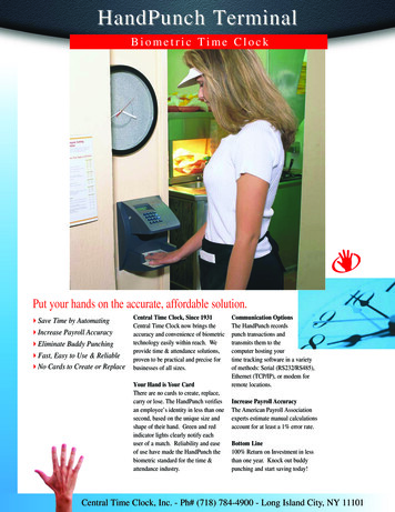
HandPunch 3000/4000 ManualPlanning an InstallationSitePreparationBefore you begin installation, check the site blueprints, riser diagrams, andspecifications for important information about the HandPunch’s location andother systems that will connect to the HandPunch. Look for any existing wallpreparations and wiring that other contractors may have installed for theHandPunch. A wire routing layout diagram (see Figure 3-2 on page 25) isprovided to assist in planning.HandPunchPlacementThe recommended height for the HandPunch platen is 40 inches (102 cm)from the finished floor. The HandPunch should be out of the path of pedestrianand vehicular traffic, and convenient too, but not behind the door it iscontrolling. Avoid placing the HandPunch where users must cross the swingpath of the door. The HandPunch should be in an area where it is not exposedto excessive airborne dust, direct sunlight, water, or chemicals.40 in. (102 cm.)Figure 2-1: HandPunch Placement RulesNOTEFor the following sections, Recognition Systems does not supply hardwareitems such as door control relays, door locks, switches, relays, communicationsor power wiring.Page 11
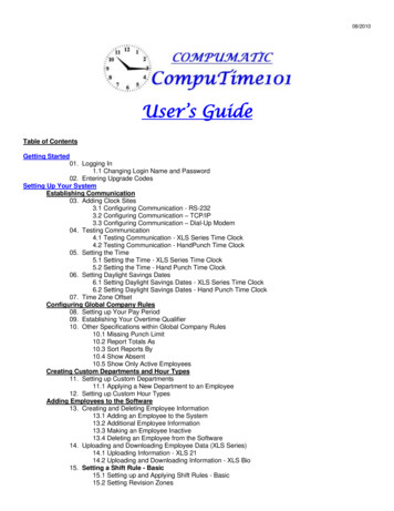
HandPunch 3000/4000 ManualMechanical InstallationSelect an installation location based on the guidelines provided in the Planningan Installation section beginning on page 11.Wall PlateInstallationNOTEFor the following instructions protect the HandPunch from the dust and debrisgenerated during the wall plate installation process.1. Remove the wall plate from the packing carton. Refer to Figure 3-1 for allwall plate references in the following section.HOLE2 UPPER SCREWSSURFACECONDUITENTRYFigure 3-1: Wall Plate2. Measure and mark a point 48 1/2 inches (123 cm) from the surface of thefinished floor. This point will correspond to where the top-center point of theHandPunch should be mounted.3. For a hollow wall, drive a small nail into the wall at the mark and hang thewall plate from the leveling hole located near the top of the wall plate.4. For a solid wall, hold the wall plate against the wall, centering the levelinghole over the mark in the wall.Page 23
Mechanical Installation5. Align a bubble level with the top edge of the wall plate and gently rotate thewall plate until the bubble level shows that the top edge of the wall plate islevel.6. Secure the plate to the wall using heavy masking tape.7. Using the wall plate as a template, mark the locations of the two upper screwholes and the three lower screw holes.8. For a concealed wiring connection, trace the outline of the open area in thecenter of the wall plate. Identify and mark a 1/2 inch hole through which theHandPunch’s wiring will be mounted.9. For a surface conduit wiring connection, mark the two conduit clamp holesat the right side of the wall plate.10. Remove the wall plate, masking tape, and the nail (if used).Mounting theWall Plate1. For a hollow wall, use the provided hardware to mount the wall plate. Use thetwo auger style fasteners for the upper two mounting holes. Use the togglebolts for the three lower mounting holes.2. For a solid wall, use expansion bolts to mount the wall plate. For all fivemounting holes, drill a 1/4 inch diameter hole, 1/4 of an inch deeper than thelength of the expansion anchor.Routing theWiring1. For a concealed wiring connection, drill a 1/2 inch hole in a convenient location within the open area of the wall plate. Pull the wiring to enter the HandPunch through this hole in the open area.2. For a surface conduit wiring connection, drill a 1/4 inch diameter hole, 1/4 ofan inch deeper than the length of the expansion anchor for each of the twoconduit clamp holes. Route 1/2 inch conduit to the HandPunch, ending theconduit between the two conduit clamp holes. Pull the wiring to enter theHandPunch through the conduit.Page 24
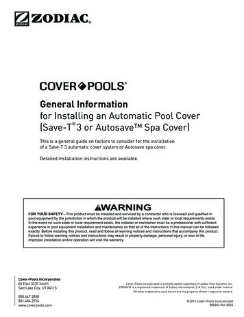
HandPunch 3000/4000 ManualWIRE ENTRY POINTFOR RJ-11 JUNCTION BOXWall PlateSURFACECONDUITENTRY POINTCL1.25"(3 cm)50" Reference(127 cm)to Top ofWall PlateWIRE ENTRY POINTFOR SURFACERJ-11 BOX2"(5 cm)CL HandPunch42.75"(108.6 cm)42.5"(108 cm)40.75"(103 cm)Finished FloorFigure 3-2: HandPunch Wire Routing LayoutAttaching theHandPunch1 Remove the HandPunch from its carton.2. Align the sleeves of the back plate with the pins of the wall plate and slide theHandPunch to the left as shown in Figure 3-3.Page 25
Mechanical InstallationHOLE2 UPPER SCREWSSURFACECONDUITENTRYREAR OF TERMINALFigure 3-3: Attaching the HandPunch to the Wall Plate3. The HandPunch is now ready for its wiring connections.Page 26
HandPunch 3000/4000 ManualWiring ConnectionsOnce the HandPunch is attached to the wall plate the wiring connections to theHandPunch can be made (see Figure 4-1).WALLPowerConnectorsRJ-11RS-422ResetSwitchJ7 BatteryJumperWall PlateTerminalStrips Optional Modem Serial RS-232or EthernetTop ofTerminalTop of HandPunchFigure 4-1: Wiring ConnectionsWiringExamplesThe following Tables provide the pin outs for the terminal strips on theHandPunch. Table 2 on page 30 provides the pin outs for TS-2: Input Connections.Table 3 on page 30 provides the pin outs for TS-3: Card Reader and OutputConnections.Table 4 on page 30 provides the pin outs for the Serial RS-232 Connection.Table 5 on page 31 provides the pin outs for the RS-422 HandPunch toHandPunch Network Connection The following Figures provide the pinout diagrams for the RJ-11 and RS-232connectors Figure 4-2 on page 31 provides the pinouts for J3, the RJ-11/RS-422Network ConnectionFigure 4-3 on page 32 provides the pinouts for J8, the RS-232 Serial PrinterConnection.Page 31
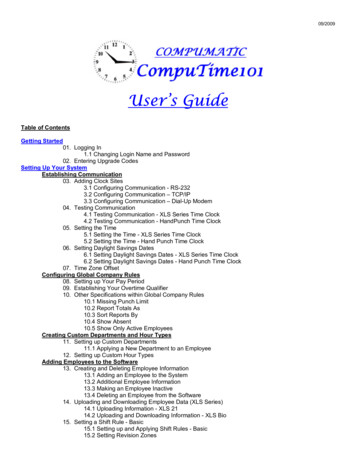
HandPunch 3000/4000 ManualClosing the HandPunchBefore closing the HandPunch clear all dust and debris away from theHandPunch. With the wall mount latch in the unlocked position, swing the bodyof the HandPunch up and lock the latch into place with the key provided with theHandPunch (see Figure 6-1).NOTENOTEDust and debris surrounding the HandPunch can drastically affect the terminal’soperation. It is important to ensure the HandPunch is free from dust and debrisbefore closing the terminal.Do not force the HandPunch onto the wall mount latch when the latch is in thelocked position.Wa l l P l a t eLatchgoceRSmetsy.cnI snoitinKeyoNLOCKUnlocked PositionWa l l P l a t eLatchKeyLocked PositionFigure 6-1: Closing the HandPunchPage 45
HandPunch 3000/4000 ManualAppendix ATips for a successful InstallationHandPunch Think of the HandPunch as a cameraClean the HandPunch before it gets dirtyUse non-abrasive cleaners such as glass cleaners and non-abrasive andclean clothsMake cleaning the HandPunch part of Janitorial programDo not remove the foam backing from the wall mounting plateSeal any holes made in the wall for wire routing, so that dust will notblow into the HandPunchLocation Mount all HandPunchs in a network so that the top of the platen is 40”off of the floorIf an enrollment HandPunch is used make sure that it is placed with thetop platen 40” off of the floor and not sitting directly on top of a desk,this will help to eliminate “bad enrollments”Mount the HandPunch so that it is not difficult or dangerous to verifythen open the doorIt is not recommended to mount the HandPunch in an area where thereis airborne dust, in the path of direct sunlight, or where the HandPunchcan be exposed to water or corrosive gassesEnrollment Educate the Enrollee on Hand GeometryExplain enrollment processTrain Enrollee on hand placement-Practice placing hand on platen-Make sure hand is flat on platen-Close finger towards the center of hand-Fingers gently touch finger pinsLet the enrollee enter in their own ID number during the enrollment process, this forces the Enroller to step aside allowing the Enrollee to standin front of the HandPunch helping to eliminate “bad enrollments”Call (718) 784-4900www.centraltimeclock.comPage 71
HandPunch Initial Setup & Enrollment InstructionsBefore you start: How to Install clock Install clock so bottom of clock is 40 inches above the ground at waist height- Connect CAT-5 cable from clock's network port & connect other end to network hub or routerPlug in reader to standard power outlet (110/120 Volts), 4 ft cable provided (Don't hard wire)Program IP Address, Subnet Mask & Default Gateway into clock (Select 2# & then Set Serial)Activate clock by calling Clock Support at Ph# 718-784-4900After clock is activated you may begin enrolling usersEnroll yourself as Supervisor To get entry to menus, press: Clear and EnterEnter password followed by # key:4#To enroll Supervisor press(*) to skip add employee:Press *Enroll Supervisor:Press #Enter the supervisor ID, followed by the Enter key: XXXthen EnterPlace Hand 1/3 (remove hand)Place Hand 2/3 (remove hand)Place Hand 3/3 (remove hand)The supervisor is now enrolledEnroll your employees To get entry to password level Press:Clear and EnterEnter your Supervisor ID, followed by the Enter key: XXX then EnterPlace your hand for verificationEnter password followed by # key:4#Enroll Employee:Press #Enter the Employee ID, followed by the Enter key: XXX then EnterPlace Hand 1/3 (remove hand)Place Hand 2/3 (remove hand)Place Hand 3/3 (remove hand)The employee is now enrolledDemonstrating Tips To Ensure Best Enrollment Demonstrate how an employee would punch prior to enrolling them- This allows the person to see how the hand is placed into the reader correctly Repeat employee's unique pin number to them before they try to punch There are green & red indicator lights on clock to highlight if punch was recorded successfulThe score that appears after a punch indicates the accuracy of hand placement (0 Perfect)Call (718) 784-4900www.centraltimeclock.com
HandPunch Initial Setup & IP Address Setup InstructionsSet IP Address To get entry to password level Press: Clear and EnterEnter your Supervisor ID, followed by the Enter key: XXX then EnterPlace your hand for verificationEnter password followed by # key: 2#Press (*) to skip set languagePress (*) to skip set date formatPress (*) to skip set date and timePress (*) to skip set addressPress (*) to skip set id lengthSet Serial: Press #Verify/Enter IP Address (make sure to use all 3 numbers in each octet)Example: 192.168.001.105Verify/Enter Gateway (make sure to use all 3 numbers in each octet)Example: 192.168.001.001Verify/Enter Host Bit9600 Baud: Press #Clock Activation Instructions:Once the clock is installed with the proper Static IP Address info configured in the clockand the CAT-5 network patch cable is connected from the clock to DSL Modemplease give Central Time Clock a call at Ph# 718-784-4900 and ask for HandPunchsupport to test communication. Once the clock is activated you will be able to startenrolling new users and begin punching.Call (718) 784-4900www.centraltimeclock.com
Once the clock is installed with the proper Static IP Address info configured in the clock and the CAT-5 network patch cable is connected from the clock to DSL Modem please give Central Time Clock a call at Ph# 718-784-4900 and ask for HandPunch support to test communication. Once the clock is activated you will be able to start