Transcription
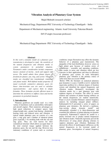
Jnl. M echanisms Volume 3, pp.131-148/Pergamon Press 1968/Printed in Great BritainStructure and Analysis of Planetary Gear TrainsProf. Dr. Zoltan Levai*Received 9 February 1968AbstractBoth compound and internal or external planet gears are considered as well asthe paired planet gears. It is stated that the simple planetary gear train consistingof two central gears, one or more planet gears and one arm, has 34 different types.All 34 types can be derived from one general form of the simple planetary gear train.The family tree of planetary gear trains is given. Every kind of joined and unitedplanetary gear trains w hich have more than two central gears, can be separatedinto two or more simple types. Uniform mathematical and graphical methods arepresented for analysing kinematical, torque and force characteristics of planetarygear trains. Some of the methods are new.Zusammenfassu ng-Struktur und Analyse der Planetengetriebe : Z. LewaiIn der Arbeit sind zusammengesetzte innere und aussere Planetengetriebebetrachtet, ebenso wie zweistufige Planetengetriebe. Es wird festgestellt, dass daseinfache Planetengetriebe, bestehend aus zwei zentralen Zahnradern, einem odermehreren Planetenradern und einem Arm, 34 verschiedene Arten aufweist.Aile 34 Arten konnen aus einer allgemeinen Form eines einfachen Planetengetriebesabgeleitet w erden. Der Stammbaum der Planetengetriebe ist angegeben. J edeArt von vereinten Planetengetrieben, die mehr als zwei Zentralrader besitzen,konnen in zwei oder mehrere einfache Arten geteilt werden. Allgemeinemethematische und graphische M ethoden zur Analyse von kinematischenDrehmoment- und Kraft-Eigenschaften von Planetengetrieben sind angegeben.Einige der M ethoden sind neu.PaJOMc-CTpyKrypa H amuw3 nnaHeTaPHblX 3y6 1aTbiX MexamnMon: 3. JleBali.pa60TC p83CMOTpCH I l CIIO)I(Hble .If BHCWJnfC Hfll1 :Sil)'Tpe!ume f!Jr81rCT3piiblC 3y6'i8Tb!C MCX8HH3Mbla TaK)I(e Jlllyxc·ryneH'iaTI Ie nrraHeTapHhiC MexaHli3Mbi. YcTaHanmmaeTCSl 'ITO rrpocTol.f nmtHeTapHbutMeXaJIR3M, COCTOSll.l.lUH H3 ABYX l\ClHpai!blihi:X KOIICC, Oll.HOfO lfllH KCCKO.flbKHX CaTCJliiHTOB lf O.UHOTOJlOttHna nMeeT 34 pa3.rlH'liii JX nmon. B ee 34 T IDJa MOTYT 6biTb BI Jne,ueHbJ R3 O,l{f!Oii o6JAcii l oPMl InnaneTapHaro MexaHli3Ma. Kall(,!II JH Tim C.flQ)KHaro If o 5'beAH8eJmaro rrrraKeTapHaro MexaH'R3MaliMC!OW8fO 6oJU,UJe 'lCM ,U!la IICHTpaJJbllblX KOIICCa MO)I(CT 61 III p a3,I(CIICH l:la }.lila MlUi 60JICC npOCTbiXTHDO!l. 06WHC MaTCM3TH'iCCKHC Jol rpa!j H'ICCKHC MeTO):tbl ,[taiOTCSl JliiJ! aHaJ1H3a KMliCManf'iCCKHX:-10MCHTOB H Cl-!IIOBblX xapaKTepWCTHK llJTilHCTapHt.IX MeXaHli3MO!l. HeKOTOpbie MCTO,llbiS!BIIRIOTCS! HOBbiM!ol.B1. IntroductionA MECHANISM is termed a planetary mechanism if it contains at least one rigid body which isrequired to rotate about its own axis and at the same time to revolve about another axis(Fig. l). Points on this body will generate epicycloids or hypocycloids. Therefore aplanetary mechanism is often called an epicyclic or cyclic mechanism.A planetary mechanism can be obtained by mounting a rigid body, often refe rred toas a planet, on a crank pin. Theoretically the crank and the planet can be d riven by different P rofessorand Headof Automotive Engineering, Budapest University of Technology, Hungary.131
132JFigure 1.motors (Fig. 2). It is not necessary to mount the motor, driving the planet, on the crankpin itself (Fig. 3). In practice, the planet is rotated by rolling it either on the outside or onthe inside of a stationary gear (Figs. 4 and 5). The axis of the stationary gear must be collinearwith the axis of the crank. The stationary gear (sun gear or ring gear) can be referred to asthe central gear. The crank is generally called the arm or carrier.cFigure 2.Figure 3.Figure 4. )\0Figure 5.A mechanism which consists of one central gear, one or more planet gears and onearm, carrying the planet gears, can be called an elementary planetary gear train (elementaryP.G.T.).In case the motion of the planet gear is required directly, the shaft of the planet gear can,for example, be coupled to another shaft (output shaft) by universal joints (Fig. 6). However,the rotation of the planet gear is seldom used directly. Generally, a second central gear isdriven by the planet gear (Fig. 7). The fact that more than one (usually three) planet gears
133are placed between the two central gears does not change the character of the P.G.T. (Fig.8). In this case the planet gears can be referred to as parallel gears because each planetgear is in mesh with both of the central gears.0Figure 6.''XJFigure 7.9Figure 8.A mechanism which consists of two central gears, one or more planet gears and onearm, carrying the planet gears, can be called a simple planetary gear train (simple P.G.T.).It is noted that in Fig. 8, there is no fixed central gear; all of the gears can rotate as wellas the arm. This is the general case; a flxed gear or fixed arm is a special case.In Fig. 8, some of the symbols used are shown; the numbers I and 2 always indicatethe central gears, 3 the arm and 4 the planet gear.Often the same planet meshes with two central gears on different pitch circles or withgears being in two different planes (Fig. 9). This type is known as a compound planetgear.luJJffLFigure 9.2
134Planet gears can be placed not only in parallel with each other but also in series, thatis one after the other (paired planet gears) (Fig. 10). In this case, there is no planet gearmesh in directly with both central gears; each planet gear meshes with only one centralgear and another planet gear. Application of paired planet gears cause a change in directionof rotation that is in the character of the P.G.T. A set of three planet gears in series ismeaningless because the direction of rotation will be the same again as in the case of singleplanet gear.Figure 10.2. Conception of P.G.T. TypesIn conclusion it can be said that a simple P.G.T. is the most advanced one if it is madewith paired compound planet gears (Fig. 11). In this figure, the dotted lines signify thatboth central gears can be either an external or an internal gear. The same P.G.T. is illustratedin Fig. 12, where the axes of the planet gears are not parallel with that of the central gears.It must be noticed that application of bevel gears does not change the character of a P.G.T.,it can only modify the numerical values of the characteristics (Fig. 13). Therefore bevelgears will not be dealt with here.Figure 11.Figure 12.Figure 13.
135Notice that the differences in character only result in new P.G.T. types. The characterdepends on(I) how many gears there are in the train; and(2) which of the gears are internal or external.The character also remains unchanged if the central gears or their shafts or the arm areset in different sequence or configuration. One does not get a new P.G.T. type by reflection,either (Fig. 14). The circumstance as to which shaft is stationary or input or output bas alsono effect on the question of type.3JrPL J ffiL22I2iFigure 14.There is a possibility of naming P.G.T. types by letters. If the letter P stands for externalgears (both central and planet gears) and the letter N for internal gears; and if the letter,whether PorN, when it refers to a planet gear, is put in brackets, then one can write for theP.G.T.'s given in Fig. 14: Type N(PP)P or its reflection: Type P(PP)N which, naturally, isthe same as Type N(PP)P. Further examples: in Fig. 10, Type P(P)(P)N, and in Fig. 8,Type P(P)N are shown.Applying paired planet gears, the axes of the central gears and that of the pair of planetgears generally do not lie in the same plane. In other words, their centers do not lie alongone straight line. In some cases the centers of both of the paired planet gears are at thesame distance from t.he center of the sungears (Fig. 15). Which of the paired planet gears-- -·- --cu----u r------tJ----I--- - Figure 15.will be closer to the axis of the central gears depends on the sizes and not on the character ofthe P.G.T. Therefore, it is not necessary (and sometimes impossible) to show the actualsizes or distances in a symbolical representation (Fig. 16).hlflJJ:E-yiL32TYPE: P(PPXPPJNFigure 16.Jrifl3TYPE P(PPXPP)N2
136It was mentioned above that central gears can be geared either internally or externally.Accordingly, one can get different P.G.T. types with uniform planet gears (Fig. 17).I 7TYPE P(PPJN2TYPf:PfPP)PFigure 17.The exchange of an external gear for an internal gear can be taken as a decrease in thediameter from some positive value to some negative one (Fig. 18). In naming the P.G.T.or·. r'·c:::.". or . . - - .,, . .?. .--.--·n-J .v··r" ·r.-. ' :r-. .Figure 18.V'. . . QCl. 3types by letters, the letter P means positive diameter and the letter N means negativediameter. A decrease in the diameter or change of its sign can be done to planet gears,too (Fig. 19), resulting in new P.G .T. types again. Of course, the absolute values of diametersare limited. Sketches band c in Fig. 19, for example, cannot be realized.\ ITYPE PfNP'NFigure 19.3. Derivation of P.G .T. Typeslt is now advantageous to determine how many types of simple P.G.T. exist. Thederivation of types from the general form given in Fig. 11, is a process of changing diameters.In certain cases a change in diameters without exchange of sign can also give new types ofP.G.T. This occurs when the diameter of certain gears become equal to each other and,consequently, the number of gears decreases (Figs. 20 and 21). An exchange of sign willresult in new types in most cases.
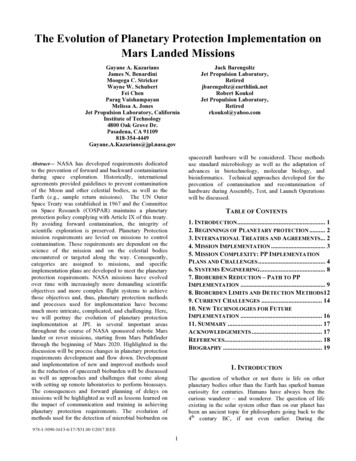
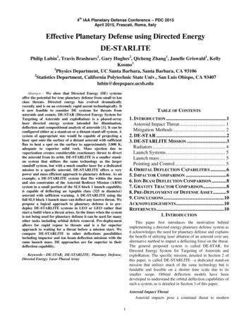
137TYPE · P(PPJN7YP :FfPJNFigure 20.iDrlrJlbl\Orl ll:t71 - J l YP . P(NN)(P) PTYr . N(PJPFigure 21.The general form is given again in Fig. 22, indicating the necessary index numbers.11Figure 22 .Table 1 contains all possible variations of external and internal gears. The variantswhich can practically be realized are denoted by bold-faced letters and given serial numbers.Some of the variants are reflection of each other. Since a reflection does not result in anew P.G.T. type, the type numbers which are being repeated are denoted by thin figures .Thin letters and the sign "-" mean that the variation cannot be realized practically. Forinstance, two internal gears cannot be in mesh with each other.On the basis of Table I , it can be said that the simple P.G.T. has 34 different types.Figure 23 illustrates the complete family tree of the simple P.G.T. It can be seen whichspecial type is derived from which more general type. Jn this family tree are also indicatedeither the signs or the proportions of the various diameters as related to the variants. Theheavier arrows show the types made by changing the sign of diameters, thin arrows show thetypes made by reducing the number of the planet gears. The types in the circles are thosemost generally used.·At first it may happen that a P.G.T. does not appear to correspond to any one of the 34types. There can be t\vo reasons for this: the order and configuration of the gears and shaftsmay be unusual or the P.G.T. in question is not a simple one but made up of joined or unitedP.G.T.-s.Figure 24 illustrates examples for unusual configuration. The first P.G.T. correspondsto type No. 8, the second one to type No. 10.
138Table 1No.TypeNo.T ypeNo.Type- - - - - - - - N NN(NP)NN(PN)NN(NN)NN(P)(P)NN (N)(P)NN NN(N)(NP)NN(N)(PN)NN(P)(NN)NN (N)(NN)NN(PP)(P)NN(NP)(P)NN(PN)(P)NN (PP)(N)NN(NN)(P)NN(NP)(N)NN P)(NP)NN (PP)(PN)NN (NN)(PP)NN(NP)(NP)NN P)NN(NN)(PN)NN(NP)(NN)NN(PN)(NN)NN(NN)(NN)N
139oo" o"""cSJ. 4 "it'0 .!.sl:JJ Cl!l .J
140hlrl LlfTYPE P(PPJ(PJNTYPE P(PPAPPJNFigure 24.A joined P.G.T. can be recognized by the fact, that in every case, it has more than twocentral gears. In every case, joined P.G.T.-s can be separated into two or more simpleP.G.T.-s. The joined P.G.T.-s shown in Fig. 25 can be separated into type No. 16 andtype No. I.TYPE p(pP)P TYPE F{PJNFigure 25.The separation is not so obvious if one of the planet gears of the first simple P.G.T. isunited with one of the planet gears of the second simple P.G.T. In this case the relatedcentral gears are united as well. This may occur when the sizes of these planet gears andtheir arm radii are equal to each other. Figure 26 shows the same type of joined P.G.T.-sJLr-fl·HlT tL :r tL:rTYPE P(P?JP TYPE PfPJN TYPE P( ffiP P( NFigure 26.given in Fig. 25, but with two of the planet gears united. Joined P.G.T.-s with united gearscan be called united P.G.T.-s. Figures 27 and 28 also illustrate united P.G.T.-s. The unitedP.G.T.-s in Figs. 29 and 30 have been constructed of three simple P.G.T.-s.TYPE 2XP(PPJPTYPE P(ppJPTYPE P(PPJPFigure 27.TYPE RPFKRP PfFHPJN TYPE P(ffi(P)P TYPE P(pJ(pJNFigure 28.
141TYPE L; P{PFJ P PfPPAPJP TYPE P{PPJP TYPE P(PB(PJ P TYPf P(PPJ PFigure 29.TYPE 2XP(PJN P(PPJP ::: TYPE P{FJN TYPE P(PP)P TYPE P{P)NFigure 30.4. Analytical M ethods of P.G.T.'s AnalysisThere are analytical and graphical methods for the theoretical investigation and designof a P.G .T. Some of these methods have been known previously.According to the Willis's analytical method [38) the simple P.G.T. can be characterizedby the "basic ratio" which is the ratio of the angular velocities of the two central gearsrelative to the arm. Choosing symbol b for the basic ratio, it can be written as(1)b Wz - W3.(2)Wt - W3The reason for using the symbol b for the basic ratio of a P.G.T. was that it is differentfrom the known velocity ratio m« or train value e. The basic ratio b of a given P.G.T. isfixed and it characterizes the P.G.T. uniquely. The velocity ratio or train value, at the sametime, can be different for a given P.G.T., depending on how the P.G.T. is applied (Table 2).Table 2. .-JLmw b,lEtmw-1-b,i, ,mi1mw 7 1fl"w1- b1, rll Jmw-- b f613 ?1 1mw b;1)
142Equation (2) can be written as follows:(3)This is the basic kinematical equation of the simple P.G.T. From it one can determineany one of the three angular velocities when the other two of them are known together withthe value of b. One could also calculate from equation (3) the angular velocity ratio betweenany two shafts when the angular velocity of the third shaft and b are given.The basic ratio b of a given P.G.T. can be determined from the diameters of the gears;namely, assuming the arm to be stationary the basic ratio will be identical with the angularvelocity ratio and will be inversely proportional to the diameters of the gears with negativesign. The formula for the general form of the simple P.G.T. is as follows :b - Dt xD42 xD4t2.D 2 xD41 xD 421(4)The sign of the diameters must be taken into account; accordingly, b may have eithera positive or a negative value. The formula (4) becomes shorter for simpler types. Forexample, the types Nos. 3, 16, 31 are the result of the condition:D421 - lD4t2'thus their formula is:b Dt x D4z.D2 x D4t(5)For the type No.1, also D 41 D 42, therefore(6)but for the type No.4 (D4 1 D412 and D42 D42t):Dtb - D2(7)Since the simple P.G.T. has three main elements (two central gears and one arm orrather their shafts), the t orques acting on them are always in equilibrium (uniform rotationassumed), thus:T 1 T2 T3 0 .(8)Furthermore, when w 3 0, one can write (by applying equation 3):Tt-(9)This gives(10)
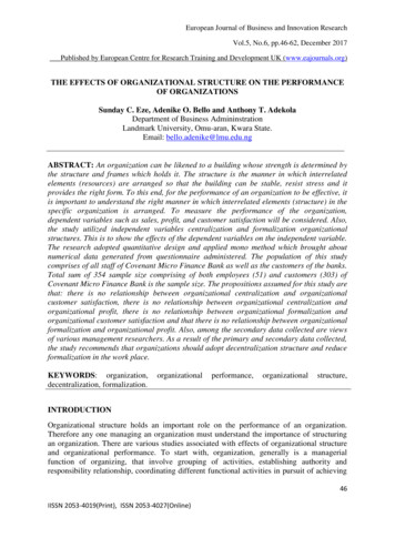
143From equatio ns (8) and (10) follows that(11)Therefore equations (10) and (ll) can be written in the form:(12)This equation gives the basic proportions of the torques for the ideal simple P.G.T.Dividing each term in equation (12) by the appropriate radii, gives the basic proportionsof the tangential forces for the ideal simple P.G.T. :(13)Multiplying each term in equation (12) by the appropriate angular velocities, gives thebasic proportions of the power for the ideal simple P.G.T.:(14)5. Graphical Methods of P.G .T. AnalysisKutzbach used a graphical method for the kinematical analysis of the P.G.T. [14].This method is based on the principle of kinematics that the instantaneous velocity of aoypoint on a rigid body being in plane motion can be determined if the velocities of two otherpoints on it are already known. A planet gear has three points which are of interest: itscenter, which is coincident with the center of arm pin, and its two pitch points, which arecoincident with the pitch points of the central gears. Consequently, if the instantaneousvelocities of these three points on the planet gear are known then the instantaneous velocityof one point on each P.G.T . element is also known. The tangential velocities are representedby vectors (Fig. 31 ). The endpoints of the vectors must lie in a straight line. If two vectorsare given, the third one can be drawn easily. By projection of the vectors on so me commonradius one obtains straight Jines, the lengths of which are pr oportional to the angularvelocities of the P.G.T. shafts.Figure 31.
144Graphical methods for the analysis of the tangential forces and torques have beenproposed by the author [19]. The method of drawing a force diagram is shown in Fig. 32.By taking first the force F3 applied on the arm pin, one has to draw three lines in thedirections shown by the arrows to get the force F 2 (sketch a). One can get the force F 1 inthe same way (sketch b). The sketch c shows all three forces together.23a,b.,Figure 32.The torque diagram looks like the force diagram with the only difference that at theintersection Q, the third line must be dropped in the radial direction 1nstead of vertically(Fig. 33).,Figure 33.Notice that the sense of the force vectors or torque lines must be specified as follows :the inside vector must have a sense opposite to that of the two outside vectors regardlessof which P.G.T. element it belongs to, provided that all three vectors are on the same sideof the vertical central line. If one of the outside vectors is on the opposite side of the verticalcentral line then its sense must be changed.The above graphical methods can be used for compound planet gears as well as forinternal planet gears (Figs. 34 and 35). Note the sense of T 1 in Fig. 35.Figure 34.
145Figure 35.However, when paired planet gears are used in a P.G.T. then the methods must besupplemented. In this case, there is no planet gear having coincident points with both ofthe central gears. For P. G. T. with paired planet gears, the author has proposed the followingmethod (the proof of this method is given in [16J and (I8D (Fig. 36).ltd12JFigure 36 .Select one of the paired planet gears (for example, the gear 31), as the main one. Erecta line through the centers of the main planet gear and the central gears. The butt of vectorV31 is at the center of the main planet gear. The butt of vector V1 is at the pitch point ofthe main planet gear and the central gear. The problem is to find the location of the thirdvector. To accomplish this drop a line through the pitch points of the other planet gearwhich is now an auxiliary one. The intersection of this line with the vertical is the butt ofthe third vector. Once this butt is found, one can sketch all the vectors and determinethe angular velocities in the known way.It must be noted that although the third vector Vi belongs to the central gear 2, it givesthe tangential velocity on the reduced radius ri and not on its pitch circle. If one is interestedin the tangential velocity V2 , one can find it by simple projection.Having found the J."ed uced radius r*, one can also construct the force and torquediagrams by the known methods. In Fig. 37, the velocity diagram of the previous P.G.T.is shown again but in this case, the other planet geaJ." had been chosen as main planet gear.The results, naturally, are the same. Notice that force Fi is different from force Fl thelatter being the foJ."ce acti ng on the pitch point of the central gear 1. The force F 1 can beobtained by reduction of Fi from radius ri to radius r 1 (see dotted lines in sketch c). Onthe other hand, the force F 2 is the actual force acting on the pitch point of the central gear 2.Force F 3 is the actual tangential comp onent of the force acting on the arm pin 32, provided
146Figure 37.that the force acting on arm pin 31 is imagined to be reduced to arm pin 32. As it is knowncertain K 1 and K 2 forces appear on both arm pins. They can be drawn from F 1 or F 2(Fig. 38). Force F 31 or F 32 corresponds to the tangential component of the resultant ofK1 and K 2 , reduced to radius r 31 or r 32 .Figure 38.Torque T1 corresponds to T 1 immediately (Fig. 37).Two further examples are illustrated in Figs. 39 and 40. One can find internal planetgears in Fig. 40.
147Figure 39.Figure 40.Both mathematical and graphical methods can be used for joined P.G.T.-s as well asfor united P.G.T.-s once the constituent parts have been recognized and separated.Finally, it must be mentioned that the reduced radius r* has its own significance.Radius r* is the radius of a central gear of a certain P.G.T. without auxiliary planet gearsbut with the same characteristics as the original P .G.T. which has paired planet gears. Sinceone can choose any one of the paired gears as a main one, one can get two different reducedradii r* (r a nd r ). Thus every simple P.G.T. with paired planet gears corresponds totwo simple P.G.T. without auxiliary planet gears. That is, one can be replaced by the other(Fig. 41).Figure 41 .
148References[I] BUGAJEWSKI E. Ober die Umlaufgetriebe und ihre Verwendung in Verbindung m it Wechsclgetrieben.R ev. Roumaine Sci. Tech. -Ser. Mec. app!. 11, 553-574 (1966).[2] BRANDENBURGER H. Wirkungsgrad unci Aufba u einfacher und zusammengeserzter 'Umlaufradergetricbe. Maschinenbau 8, 249- 253, 290-294 (1929).[3] COWIE A. Nomograph simplifies planetary gea r calculations. Machine Design 19, 155-156 ( 1947).[4] CARMICt·tAEL C. Planetary gear calculations. Machine Design 20, 165- 168 (1948).[5] G LOVER J. H. Planetary gear systems. Product Engng 36, 20, 72-79 (1965).[6] GRAHAM L.A. Planetary transmissions- lesign analysis. Machine Design 18, II, 115-119 ( 1946).[7] GRODZINSKI P. Practical theory of mechanism. Mec. Wid Engng Rec. Manchester 115, 320-321 (1944).[8] G LOvER J. H. Pla netary gear train ratios. Machine Design 33, 16, 125-128 (1961).[9] H OELL G. S. D esign of planetary gear systems. Machine Design 13, 8, 77- 78 (1941 ).[10] JENKINS A. L. Analysis of velocity ratios of epicyclic gear trai ns. Engng News 64, 629-632 ( 19 10).[11] KLEIN H . Die Planeteriider-Umlaufgetriebe. H auser, Mtinchen ( 1962).[12] KLEIN H. Auslegen von U mlaufriidergetrieben im D reiwellenbetrieb (Oberlagerungsbetrieb) ftlroptimale '()bertragungsverhaltnisse. Konstruktion 17, 361-365 ( 1965).[13] KRAUS R. Planmiissiger Aufbau von Stirnrad-Standgetrieben und -Umlau fgetriebcn. VDI.-Z. 92,933-944 (1950). .[14] K OTZDACH K. Mechanische Leistungverzweigung. Ihre Gesetze unci Anwenclu ngen. lvfaschinenbau,Der Betrieb 8, 710- 7.16 (1929).[15] L AUGHUN H. G ., HOLOWENKO A. R. and H ALL A. S. Epicyclic gear systems. Machine Design 28,132-136 (1956).[16] LiNAI Z. Ana1ytische Untersuchung ele mentarer Planetengetriebe. Acta teclm. hung. 49, Nos. 3-4(1964).[17] Lt VAI Z. Analytische Untersuchung komplexer Planelengctr iebe. Acta techn. hung. 53, Nos. 1-2 ( 1964).[18] L EVAl Z. Theory of Epicyclic Gears and Epicyclic Change-Speed Gears, p. 156. Technical University ofBuilding, Civil and T ransport Engineering (1 966).[19] LtVAI Z. Theorie des idealen einfachen Planetengetriebes. VDI.-Z. 109, 501 - 505 (1 967).[20] LovE P. P. Proportions of Epicyclic Gearing from Velocity Ratios. R. Techn. Co/f. J. Glasgow4, 516-529 (1939).(21] LEWIS D . E. and CLIFTON A . L. E picyclic gear train. Machine Design 36, No. 18, 175- 179 ( 1964).[22] MACMILLAN R. H. Epicyclic gear trains. Engineer 187, 3 18-320 ( 1949).[23] MERRITT H. E. Analysis of planetary gear trains. Machinery Lond. 41, 548-568 (1933).[24] M ERRITT H. E. Epicyclic gear trains. E ngineer 171, 190- 192, 213- 215 (1941).·[25] NIKOLAUS H. Graphische Darstellung der Drcb zahl-, Momentcn- und Leistungsverleilung in einfachrUckkehrenden Planetengctrieben 1-IIJ. Maschinenmarkt 61, 90, 29-30 ( 1961); 68, No. 12, 33- 36;N o. 49, 32- 37 (1962).[26] OBERT E. F . Speed ratios and torque ratios in epicyclic gear trains. Product Engng 16, 270-271 ( 1945).[27] POl PINGA R. Stlrnrad- Planetengetriebe, p. 130. Franckh'sche Verlagshandlung, Stuttgart ( 1949).[28] RADZIMOVSKY E. I. Planetary gear drives. Machine D esign 28, No.3, 101-110 (1956).[29] RAPPAPORT S. Simple method of determining ratios in planetary gear trains. Product Engng 24, No. 3,182-183 ( 1953).[30] R AVIGNEAOX P. Theorie nouvelle sur les trains epicycloidaux e t lcs mouveme nts relatifs. TechniqueAutomobile et Aerienne 21, 97- 106 (1930).[31] REIN A. 0. G raphical investigation of planetary gearing. T rudi Dalnevostochnm·o Gosudarst1'e11noroUniversiteta No. 9, 3-22 ( 1929).[32] SEELIGER K. Einsteg- PJanetenschaltgctriebe. Werkstatlund B etrieb 93, No. I, 12-14 ( 1960).[33] SEI!LIGER K. Das einfachc Planetengetriebe. Antriehstechnik 3, 216-221 (1964).[34) SICKLESTEEL D. T. Method for design and calculation of p!aneta(y gear sets. Desig11 News, J une 15,45-49 (1952).[35] STRAUCH H. Die Umlaufriidergctriebe, p. 122. H auser, M unc hen (1950).[36] TALBOURDET G. J. Graphical analysis of planetary gear systems. Machine Design 14, No. 8, 93-96;No.9, 91- 94; No. 10,207-210 (1942).[37] T ANK G. Untersuchung von Beschleunigungs- und Vcrwgerungsvorglingen an Planetengetrieben.VDl.-Z. 96, 295- 308 (1 954).[38] WILLIS R. Principles of Mechanism. L ongmans, Green, London ( 1841 and I 870).
the paired planet gears. It is stated that the simple planetary gear train consisting of two central gears, one or more planet gears and one arm, has 34 different types. All 34 types can be derived from one general form of the simple planetary gear train. The family tree of planetary gear trains is given. Every kind of joined and united