Transcription
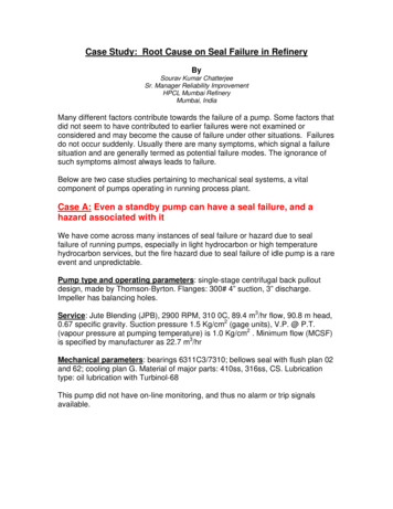
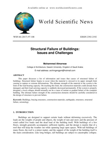
November 2015 IJIRT Volume 2 Issue 6 ISSN: 2349-6002A STUDY ON COMMON FAILURE OF GEARSJotram Patel, Gopal Sahu, Prakash Kumar SenStudent,Mechanical Engineering,Kirodimal Institute of Technology, Raigarh (C.G.)ABSTRACT:- : To objective of this paper topresent the recent development in the field ofgear failure analysis. By the help of this paper wecan know about different types of failuredetection and analyzing technique which is usedto reduce these failure from gears. The basicreasons of gear failure misalignment of gear,spalling , pitting etc, follow the reason of gearfailure. Gears generally fail when the workingstress exceeds the maximum permissible stress.Advances in engineering technology in recentyears have brought demands for gear teeth,which can operate at ever increasing loadcapacities and speeds. The gears generally failwhen tooth stress exceed the safe limit. In thisstudy the technology of gears is presented alongwith the various types of failure that gears have.The causes of these failures are studied. The typeof stress related failure due to ( fatigue failure )of gear tooth because of stress concentration isdetailed in this paperIndex Terms - gear failure, misalignment, andspalling, stress, pitting, researcher.1. INTRODUCTIONGears are the most common means of transmittingmotion and power in the modern mechanicalengineering world. A gear is a component within atransmission device that transmits rotational force toanother gear or device. A gear is different from apulley in that a gear is round wheel which haslinkages “teeth” that mesh with other gear teeth,allowing force to be fully transferred withoutslippage. A gear is a machine element designed totransmit force and motion from on mechanical unitto another. The design and function of gears areusually closely associated; various types of gearshave been developed to perform different function,the most common of these being spur gears, helicalgears, straight and spiral bevel gears, and hypoidgears. The change the rate of rotation of machineryshaft and also the axis of rotation, for high speedmachinery, such as an automobile transmission, theyare the optimal medium for low energy loss and highIJIRT 142738accuracy. Their function is to convert input providedby prime mover into an output with lower speed andcorresponding higher torque. Toothed gears are usedto transmit the power with high velocity ratio. Thecharacteristics of these various gear types arediscussed in most mechanical design texts like allmechanical components, gears can and do fail inservice for a variety of reasons. In most cases, exceptfor an increase in noise level and vibration, total gearfailure is often the first and only indication of aproblem. Many modes of gear failure have beenidentified, for example fatigue, impact, wear orplastic deformation. Of these, one of the mostcommon causes of gear failure is tooth bendingfatigue. Fatigue is the most common failure ingearing. Tooth bending fatigue and surface contactfatigue are two of the most common modes offatigue failure in gear. Several causes of fatiguefailure have been identified. These include poordesign of the gear set, incorrect assembly ormisalignment of the gear, overloads, inadvertentstress raisers of subsurface defects in critical areas,and the use of incorrect materials and heattreatments [1]. A gear is a rotating machine parthaving cut teeth. Which is meshing the gear teeth totransmit the torque? A geared device can be changethe speed, direction of power sources and magnitude[2]. The tooth meshing on another gear of nonrotating parts is called rack. When it a rotation itprovide transmission in analogous to the wheels inpulley. It is the cylindrical shaped its teeth areparallel in axis. its wide range of application mostcommonly used[3]. Gear failure can occur in variousmodes. In this chapter details of failure are given. Ifcare is taken during the design stage it to preventeach of these failures a sound gear design can beevolved. The gear failure is explained by means offlow diagram in Fig1.1. GEAR FAILUREGear failure can occur in various modes. In thispaper details of failure are given. If care is takenduring the design stage itself to prevent each of thesefailure a sound gear design can be evolved. The gearINTERNATIONAL JOURNAL OF INNOVATIVE RESEARCH IN TECHNOLOGY301
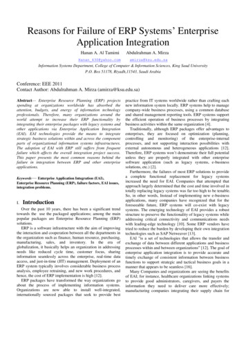
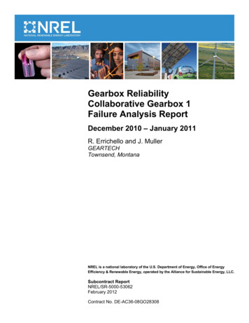
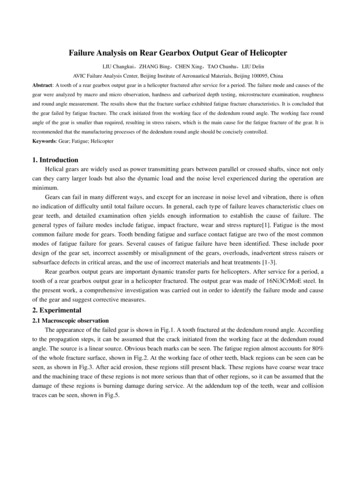
November 2015 IJIRT Volume 2 Issue 6 ISSN: 2349-6002failure is explained by means of flow diagram inFig1 there are many possibilities to describe,Fig.1 Different modes of failureClassify and evaluate gear failure. Several authorshave studied gear failure and defined different waysto classify them: An accepted way to describe gear failure isassociated with the definition: “A gear hasfailed when it can no longer do efficientlythe job for which it defined” [4]. Gear failure can be separated intolubricated-related failure, like overloadbending and fatigue and non lubricatedrelated failure, like Hertzian fatigue (pittingwear and scuffing). These classificationsare described in Erricho [5]. Gear failure can be divided into gear toothflank failure like pitting, scuffing and wearor failure modes on gear root fillets, likebending, and impact.[6]. In 1973 Shipley divided gear failure in theirfrequency of occurrence. [7] He is dividedit into:o Fatigue : Tooth bending, surfacecontact (pitting or spalling), rollingcontact, thermal fatigueo Impact: Tooth bending, tooth shear,tooth chipping, case crushing, torsionshear.o Wear: Abrasive, adhesive.o Stress rupture: Internal, external.2.1. SCORINGIJIRT 142738Scoring is due to combination of two distinctactivities: First, lubrication failure in the contactregion and second, establishment of metal to metalto metal contact. Later on, welding and tearingaction resulting from metallic contact removes themetal rapidly and continuously so far the load, speedand oil temperature remain at the same level. Thescoring is classified into initial, moderate anddestructive.2.1.1 INITIAL SCORINGInitial scoring occurs at the high spots left byprevious machining. Lubrication failure at thesespots leads to initial scoring or scuffing as shown inFig 3.1 Once these high spots are removed, the stresscomes down as the load is distributed over a largerarea. The scoring will then stop if the load, speed andtemperature of oil remain unchanged of reduced.Initial scoring is non-progressive and has correctiveaction associated with it.Fig.2 Initial scoring2.1.2 MODERATE SCORINGAfter initial scoring if the load, speed or oiltemperature increases, the scoring will spread overto a larger area. The scoring progresses at tolerableINTERNATIONAL JOURNAL OF INNOVATIVE RESEARCH IN TECHNOLOGY302
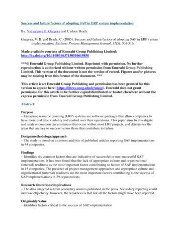
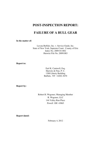
November 2015 IJIRT Volume 2 Issue 6 ISSN: 2349-6002rate. This is called moderate scoring as shown inFig.3.2Fig.3 Moderate scoring2.1.3. DESTRUCTIVE SCORINGAfter the initial scoring, if the load, speed or oiltemperature increases appreciably, then severescoring sets in with heavy metal torn regionsspreading quickly throughout as shown in Fig.3.3Scoring is normally predominant over the pitch lineregion since elasto-hydrodynamic lubrication is theleast at that region. In dry running surfaces mayseisze.Fig.5 Abrasive wear2.2.2. ADHESIVE WEARResult from high attractive forces of the atomscomposing each of two contacting, sliding surfaces.Teeth contact at random asperities and a strong bondis formed. The junction area grows until a particle istransferred across the contact interface.Fig.6 Adhesive wearFig4. Destructive scoring2.2. WEARA surface phenomenon in which layers of metal areremoved, or “worn away,” more or less uniformlyfrom the contacting surfaces of the gear teeth. Weardescribes a loss or removal of material of gearflanks. In terms of gear failure, it is more adeterioration of a gear profile, for instance, a damageof a tooth layer. Adhesive and abrasive wear areimportant modes of wear. Abrasive wear occurswhen a surface is cut away by abrasive particles.2.2.1. ABRASIVE WEARAbrasive wear has taken place, contacting surfaceshow sings of a lapped finish, radial scratch marksor grooves, some other unmistakable indication thatcontact has taken place .IJIRT 1427382.2.3. EXCESSIVE WEARThis is simply normal wear which has progressed tothe point where a considerable amount of materialhas been removed from the surfaces. The pitch lineis very prominent and may show signs of pitting.Fig.7 Excessive wear2.2.4.CORROSIVE WEARINTERNATIONAL JOURNAL OF INNOVATIVE RESEARCH IN TECHNOLOGY303
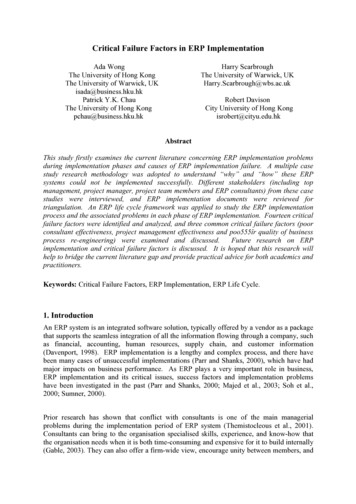
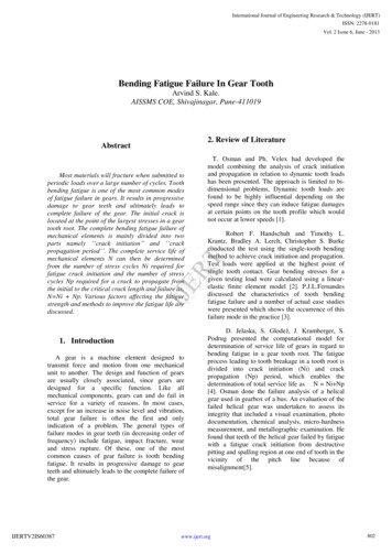
November 2015 IJIRT Volume 2 Issue 6 ISSN: 2349-6002This is a deterioration of the surface due to chemicalaction. It is often caused by active ingredients in thelubricating oil, such as acid, moisture, and extremepressure additives.Fig.8 corrosive wear2.3. FATIGUE/ PITTING OF GEARSFatigue occurs under repeated stresses which arelower than ultimate tensile strength and higher than“fatigue limit”, pitting is the most common mode offatigue and particular form of spalling.Pitting is a surface fatigue failure of the gear tooth.It occurs due to repeated loading of tooth surface andthe contact stress exceeding the surface fatiguestrength of the material. Material in the fatigueregion gets removed and a pit is formed. The pititself will cause stress concentration and soon thepitting spreads to adjacent region till the wholesurface is covered. Subsequently, higher impact loadresulting from pitting may cause fracture of alreadyweakened tooth. However, the failure process takesplace over millions of cycles of running. There aretwo types of pitting, initial and progressive.2.3.1INITIAL/INCIPIENT PITTINGInitial pitting occur during running- in period wherein oversized peaks on the surface get dislodged andsmall pits of 25 to 50 μm deep are formed just belowpitch line region. Later on, the load gets distributedover a larger surface area and the stress comes downwhich may stop the progress of pitting.Fig9 Initial pittingIn the helical gear shown in Fig.9 pitting started as alocal overload due to slight misalignment andprogressed across the tooth in the dedendum portionto mid face. Here, the pitting stopped and the pittedIJIRT 142738surfaces began to polish up and burnish over. Thisphenomenon is common with medium hard gears.On gears of materials that run in well, pitting maycease after running in, and it has practically no effecton the performance of the drive since the pits thatare formed gradually become smoothed over fromthe rolling action. The initial pitting is nonprogressive.2.3.2. PROGRESSIVE OR DESTRUCTIVEPITTINGDuring initial pitting, if the loads are high and thecorrective action of initial pitting is unable tosuppress the pitting progress, then destructive pittingsets in. Pitting spreads all over the tooth length.Pitting leads to higher pressure on the unpittedsurface, squeezing the lubricant into the pits andfinally to seizing of surfaces. Pitting begins on thetooth flanks near the line along the tooth passingthrough the pitch point where there are high frictionforces due to the low sliding velocity. Then itspreads to the whole surface of the flank.Fig.10 Tooth surface destroyed by extensive pittingTooth faces are subjected to pitting only in rare casesfig11 shows how in destructive pitting, pitting hasspread over the whole tooth and weakened tooth hasfractured at the tip leading to total failure.Fig.11 Whole tooth is destroyed by extensive pitting2.3.3. FLAKING/SPALLINGINTERNATIONAL JOURNAL OF INNOVATIVE RESEARCH IN TECHNOLOGY304
November 2015 IJIRT Volume 2 Issue 6 ISSN: 2349-6002In surface-hardened gears, the variable stresses inthe underlying layer may lead to surface fatigue andresult in flaking (spalling) of material from thesurface as shown in Fig.122.3.7. PITTING- FROSTINGFrosting usually occurs in dedendum portion of thedriving gear first aatd later on the addendum asshown in Fig15. The wear pattern doesn’t havenormal metal polish but has etched-like finish.Under magnification, surface reveals very finemicro-pits of 2.5μm deep. These patterns follow thehigher ridges caused by cutter marks. Frostingresults from very thin oil film and some asperitycontact.(a) Flaking(b) SpallingFig.12 Flaking/Spalling2.3.4. PITTING – SUBSURFACE ORIGINFAILUREFig.13 shows the subsurface origin failure.Fig.13 Subsurface origin failure2.3.5. PITTIN – SURFACE ORIGIN FAILUREFailure modes in gear namely the surface originfailure is shown in Fig.14Fig.15 Frosting2.4 CRACKINGCracking starts with small stress raisers quite in theroot of a gear. This causes unsuspected overloadswith a high sliding speed which raises thetemperature of the hardened case. Cold lubricationand hot gears leads to thermal fatigue cracks orhardening cracks associated with heat treated gears.Grinding cracks are also a result of localizedoverheating but it occurs on the tooth surface afterthe tooth finished grinding on the gear tooth pair.Process Related failure can be of following types: Quench Cracks, Grinding cracks Grinding cracks Nicks, scratches Electric arcing Grinding “Burns” Improper Edge BreaksFig16 failure by cracking2.5 FRACTUREFig.14 Surface origin failureIJIRT 142738INTERNATIONAL JOURNAL OF INNOVATIVE RESEARCH IN TECHNOLOGY305
November 2015 IJIRT Volume 2 Issue 6 ISSN: 2349-6002Fracture is also called tooth breakage or rupture. Itis one of most dangerous gear failure because thegear could be damaged or it might destroy othercomponent like shafts or bearings. Brittle fracture isa rapid crack with less deformation while ductilefracture has a deformation before a part of a gearbreaks. A combination of brittle and ductile fractureis called mixed mode fracture. Shear fracture iscaused by an overload of a single tooth. It starts witha weak point within a gear which builds up higherstresses than the strength of material allows.Therefore a small crack can grow and a tooth mightbreak off. Depending on the way in which thefracture occurs, it can be of following types: Overload Random F
gear failure analysis. By the help of this paper we can know about different types of failure detection and analyzing technique which is used to reduce these failure from gears. The basic reasons of gear failure misalignment of gear, spalling , pitting etc, follow the reason of gear failure. Gears generally fail when the working