Transcription
FeatureCAM Post Processor Reference ManualTable of ContentsHow to Open a Post Processor for editing . 2Formats menu . 4What are Reserved words . 4Numeric . 4String . 4System and logical . 5Examples of conditional statements . 5How to Configure reserved words . 5User Defined Variables . 7Turning reserved words . 9Numeric . 9Numeric canned cycle block words . 11Numeric circular block words . 12Numeric drilling and threading type cycle words . 13Logical reserved words . 14String reserved words . 16Milling reserved words . 19Numeric reserved words . 19Logical reserved words . 22String reserved words . 23Turn/Mill reserved words . 25Numeric reserved words . 26Logical reserved words . 27String reserved words . 27Multi-turret reserved words . 28Using expressions in formats. 29Numeric operators . 29Logical operators . 30Examples. 31String operators . 31Example . 33Formatting of Numbers in Post . 33Suppressing printing of an expression . 33Comments . 33Entering mixed printable ASCII and non-printable codes . 35Previous Reserved Word Value. 35Incremental programming rules . 35Sync Codes in FeatureCAM Posting . 35Introduction. 35Xbuild Reserved Words . 36Basic Synchronization in the Post . 37Synchronization for Subspindle Transfer . 37Advanced Notes . 38Page 1
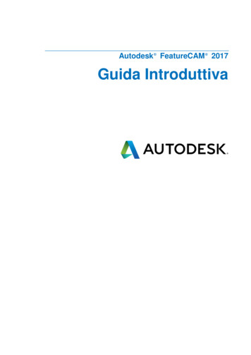
FeatureCAM Post Processor Reference ManualHow to Open a Post Processor for editingYour current post processor is located at the bottom right of your FeatureCAM screenTo open the post double click your left mouse button on the post processor name.Click on the Edit Button to start editing the current post processor.Xbuild will now open the post processor reading for editing.Click on Formats Menu and then Program Start to show the code for generating the start of the NC program.Page 2
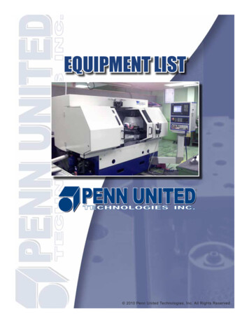
FeatureCAM Post Processor Reference ManualThe code for the Program Start will now be opened ready for editing similar to belowIf the Upper Turret is active then the start-up code will be formatted as below%O6969(PUMA MX2000ST 31I CONTROL)(UPPER TURRET PROGRAM)G0 G40 G99 G18 G80 G21G10 P0 Z0 (DATUM RESET)G10 L2 P1 X0 Y0 (Z?) C0 (G54)]G10 L2 P2 X0 Y0 (Z?) C0 (G55)G28 U0 V0G28 W0M34M900 (WAIT CODE)M1Page 3
FeatureCAM Post Processor Reference ManualFormats menuThe XBUILD Formats menu enters specific program formats for the various blocks which can appear in a partprogram. Each format is made up of combinations of reserved words, literals, comments, and user-definedvariables.The Formats menu lists a number of generalProgram - formats that are used in almost every part program, and include commonly used formats (for exampleProgram Start, Tool Change, Segment Start, Program End).Move - formats include the rapid and feed moves which make up the largest portion of any part program (forexample Rapid, Linear, Circular). These program formats must be carefully defined.Macro - formats include Open Macro, Close Macro, Macro Call, In-Macro Linear, and In-Macro Circular.The Macro formats are not available for turn posts.Cycle - formats include most of the canned cycles which are found in many controls (for example Deep Hole, Tap).Custom - a custom format is used as a place holder for a block of code that may be used in several differentformats. The system reserved word INCLUDE: is placed into the appropriate section of a format that uses theblock of code from the custom format. The name of custom format should be inserted after colon: INCLUDE:Custom Format Name .Each of these groups contains specific formats which, when selected, are displayed in the Formats editor.The formats use specific reserved words, which are discussed separately for each post type. For example, millingreserved words can be found under the Mill Post section, turning reserved words can be found under the TurnPost section and so on.What are Reserved wordsReserved words are specific words that are used in writing the post in XBUILD. These words are 'reserved'because they have a special meaning in FeatureCAM, and cannot be used for anything else. They are placeholders that will later be replaced with values provided by FeatureCAM when it generates the NC code.Reserved words are referenced in formats by enclosing each word with angular brackets . Additional ASCIIcharacters (for example X, Z and F) are used to specify the letter for each word address.In XBUILD, you can see the reserved words from:The CNC-Info Words-N menu or the File WordList menu in the Formats editor.In XBUILD, there are several types of reserved words:NumericNumeric reserved words are replaced by their numeric values when Post is executed. For example, thenumeric reserved word X-COORD is replaced by the current X axis coordinate position. You can configurethe output format of numeric reserved words via the Words Info dialog (CNC-Info Words option).Numeric reserved words can be preceded by the symbols , or @ ( name , or @name ). The prefixsignals Post to output the previous value of a reserved wordStringPage 4
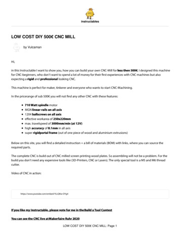
FeatureCAM Post Processor Reference ManualString reserved words provide a set of characters that were previously defined in the NC Codes dialog (toopen it, select CNC-Info NC codes from the menu).For example, G01, G02, or M03 could be strings that were previously defined as MOTION and SPINDLE .System and logicalSystem and logical reserved words are used together to set up conditional statements that are evaluated byXBUILD. Depending on whether a conditional statement is TRUE or FALSE, XBUILD either includes or omitscertain data from the program format. IF First element in a conditional statement, always followed by a logical reserved wordto verify that a condition is TRUE. IFNOT First element in a conditional statement, always followed by a logical reserved wordto verify that a condition is FALSE. THEN Second element in a conditional statement, placed after a logical reserved word. ELSE Third element in a conditional statement following an IF logical reservedword THEN to output an alternative decision. ELSEIF Third and higher element in a conditional statement to verify that a condition isTRUE. Used to evaluate multiple alternative decisions within an IF ENDIF block. ELSEIFNOT Third and higher element in a conditional statement to verify that a condition isFALSE. Used to evaluate multiple alternative decisions within a single IF ENDIF block. ENDIF Last element in a conditional statement. This must be on a line by itself. INCLUDE:CustomFormat Name Operates like a subroutine by calling a custom format from within another format.The custom format is used to eliminate duplicating large blocks of code in morethan one format.Examples of conditional statements IF Logical Reserved Word THEN {N SEQ } . . . ENDIF Or IFNOT Logical Reserved Word THEN {N SEQ } . . . ENDIF In the conditional statement below, for example, the data between the words THEN and ENDIF isoutput only if in a turning operation the constant surface speed is on. IF CSS-ON THEN {N SEQ }G96S CSS-SPEED EOB ENDIF How to Configure reserved wordsWhen any of the Words commands are selected from the CNC-Info menu (for example, Words-1), theWords Info dialog is displayed showing a table of numeric reserved words.Page 5
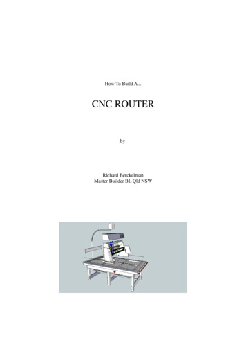
FeatureCAM Post Processor Reference ManualUse the three buttons at the bottom of the dialog, labelled OK, Cancel and Next, to keep the changes made,exit the table without saving any changes, and advance to the next Words Info dialog respectively.The words tables contain the format (symbolic name, numeric parameters and factors) for each numericreserved word.The LD ZR, TRL ZR, DEC PT, UNS V, and SIGN fields for each reserved word all toggle On/Off. Tochange an item in the table, select/deselect the check box in the appropriate column for that item.To select the Format or Factor field for any of the reserved words, move the cursor to the appropriate boxand double-click the mouse there; the selection is highlighted. To change the format or factor, type the newvalue, then press Enter.The first column (far left side) in the tables identifies the symbolic name (sometimes abbreviated) of eachnumeric reserved word.All of the words in the table that apply to the NC machine must be configured.LD ZR - leading zeros are output if this option is toggled On. Zeros are output in all leading positions of thevalue, excluding significant digit locations (for example, 1" with a 3.4 format would output two leading zeros:001).TRL ZR - trailing zeros are output when this option is set to On. Zeros are output in all trailing positions ofeach value output for the designated reserved word, excluding significant digit locations (for example, 10"with a 3.4 format would be output with four trailing zeros as 100000).DEC PT - is used to turn the Decimal Point Character On/Off (for example, when DEC PT is toggled ON,100" is output as 100.0).The decimal character (either a , representing the European decimal, or a . representing the US/UK decimal)is specified in the General Info dialog. To open it, select CNC-Info General from the menu.UNS V - when the Unsigned Value option is on, the number is output without its sign. This is often usefulfor distances. SIGN - when the Plus Sign is toggled ON, the plus sign ( ) is output for positive integers.Format - specifies the number of digits in the numeric value, represented by each numeric reserved word.Numbers are specified as N.n, where N represents the maximum number of digits to the left of the decimalpoint, and n is the maximum number of digits to the right of the decimal point. For example, entering 3.4specifies a maximum , or - departure of 999.9999, or a minimum departure of 0.0001.Use the Words Info dialog to specify a numeric representation for each reserved word that requires it.Factor - is used to modify numeric values during post processing. Each value that is output by Post ismultiplied by its factor. For example, some controls require arcs to be calculated from centre to start point.This requires a -1 factor for ARC-Z and ARC-X .Page 6
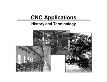
FeatureCAM Post Processor Reference ManualUser Defined VariablesSometimes you will need to create your own variables for doing calculations or to keep a track of a particularcondition which you may need to test later on.User defined variables must be declared in the PROGRAM START Section.This can be done by placing them directly in The PROGRAM START by using the Include Reserved word.This will include all variables that have been defined in the Formats – Custom – VARIABLES SectionPage 7
FeatureCAM Post Processor Reference ManualAll the following variables will be declared in the PROGRAM START Section.This is an example of a user defined variable[:prev oper type " "]It must be placed with [ ] brackets and needs a : in front of the name so that the variable value won’t be sentto the NC code.In this example we are setting the initial value of the variable to be blank. Any user defined variable needs tobe declared in the Program Start section of the post, normally by using a INCLUDE:VARIABLES statement.Sometimes you will need to save a condition as you will need to test for it in another section of the postprocessor as an example you can save the current type of process either Turning or Milling by including thefollowing code.[# ] IF MILLING THEN [# ][:prev oper type "MILL"][# ] ENDIF We can then test the user defined variable later to decide what code we need to send to the NC program[# ] IF [eq(prev oper type,"MILL")] THEN Here is an example which is using several user defined variables to do a number of calculations andformatting them for the NC program.[#][:p1 sav P1 ][#][:fix ( FIXTURE 0)][#][:no of datums (p1 sav 0)][#][:datum ceil(fix / no of datums)] EOB [#][#][:datum face no (540 datum)] EOB [#]IF 91 #[T 3.0 1:datum face no] NE 1 93 GOTO [T 4.0 1:n num n num 10] EOB [#] MOTION G90 G80 G40 G54.1P FIXTURE X X-COORD Y Y-COORD B0 S SPEED SPINDLE EOB [#]G43 Z100. H COMP-NUM COOLANT EOB Page 8
FeatureCAM Post Processor Reference ManualTurning reserved wordsNumericReserved wordDefinition ABS-DEPTH Absolute Z-axis depth from Z axis origin, calculated as ZSURF - DEPTH . ABS-STEP1 Absolute first step, calculated as ZSURF - STEP1 . BAXIS-ROT Returns turning tool rotary angle where turning tool is locked in B-axis spindle.Commonly used to flip turn tools when moving from main to sub. This is not thesame as the B-angle of the tool. CALC-SPEED Calculated direct RPM speed at the path's start point; the spindle can be turnedON, or readjusted in direct RPM prior to rapid traversing to the path's start point,where CSS is turned On. The CALC-SPEED reserved word can be used toautomatically calculate the direct RPM 'turn on' speed (to turn on CSS after positionmoves), which avoids rapid traversing to and from a remote indexing point in theCSS mode. CLEARANCE Corresponds to the Clearance attribute. CLR-DEPTH CLEARANCE DEPTH COMP-NUM Compensation number passed from FeatureCAM as the Diameter offset registerin the Tool Mapping dialog, or on the Overrides tab of the Tool Properties dialog. CSS-SPEED Corresponds to the Surface Speed parameter on the Feed/Speed tab of a feature. DWELL Corresponds to the Dwell parameter for Cutoff, Groove, and Tapping. ENG-ANGLE90 90 - Engage Angle for turning or 90 Engage Angle for boring. FEED Passes the feed rate value to the word format of FEED-UPM or FEED-UPR ,depending upon the Feed Units specified in FeatureTURN. FEED-UPM Format of this word is used to pass feed rate value and/or the reserved word FEED when Use IPR is not selected on the Feed/Speed tab for a feature. FEED-UPR Format of this word is used to pass feed rate value and/or the reserved word FEED when Use IPR is selected on the Feed/Speed tab for a feature. INC-MACX X location of the pattern instance to be cut by the macro. This coordinate is notusually output in the CNC program. INC-MACZ Z location of the pattern instance to be cut by the macro. This coordinate is notusually output in the CNC program. LIFT-OFF For groove only. Corresponds to Liftoff Dist. attribute. NEXT-TL Next tool to be used, may be required by some controls. Corresponds to the Toolcolumn of the Tool Mapping dialog. NOSE-RAD Tool nose radius of an endmill or the tool tip radius of a turning or threading tool. OFFSET# Tool length offset register number, passed from FeatureCAM as the Length offsetregister in the Tool Mapping dialog, or on the Overrides tab of the ToolProperties dialog. Generally, this value is updated only in the Program Start, ToolChange, and Segment Start formats. For the finish pass of a Groove feature,however, the value may also be updated in the Rapid Move format if you havespecified a second offset register. See also OFFSET-CH . OP-ORDERNUM Used to create Psync codes for Okuma machines. Because Okuma has only onefile for both turrets, each operation needs an individual sync code that determinesthe operation order (whether synced or not). When the turrets are synced the Pcodes for both turrets are the same. R-CSS Radius value in constant surface speed; in Post, this value is set to the first Xcoordinate value. RTR-ANGLE-P The Withdraw Angle used for EZ-Path. RTR-FEED Withdraw feed rate.Page 9
FeatureCAM Post Processor Reference Manual SEQ This is a line sequence number identifier (when the word appears in a line, it issubstituted with the current sequence number, and is subsequently incremented bythe sequence step value). SPEED Spindle RPM value passed from feature Properties dialog. SP-MAX Maximum spindle RPM when CSS is On, used to set the maximum RPM at whichthe spindle should run. Corresponds to the CSS Max RPM turning attribute or theMax. speed for the current range specified on the Feeds&Speeds dialog ofXBUILD. SPINDLE-POS Subspindle position. STEPOVER For groove only. Corresponds to Stepover % * Tool Width. STOCK-ID Inner diameter of the stock - for round (tube) stock only - 0 for other types of stock. STOCK-OD Outer diameter of the stock - for round stock only - 0 for other types of stock. STOCK-TYPE Type of stock: 1.0 for block, 2.0 for round, 3.0 for N-sided, 4.0 for user-defined. STOCK-XMAX Bounding box - maximum X value, or X coordinate of the upper most corner of thebounding box for the stock in space. STOCK-XMIN Bounding box - minimum X value, or X coordinate of the lower most corner of thebounding box for the stock in space. STOCK-YMAX Bounding box - maximum Y value, or Y coordinate of the upper most corner of thebounding box for the stock in space. STOCK-YMIN Bounding box - minimum Y value, or Y coordinate of the lower most corner of thebounding box for the stock in space. STOCK-ZMAX Bounding box - maximum Z value, or Z coordinate of the upper most corner of thebounding box for the stock in space. STOCK-ZMIN Bounding box - minimum Z value, or Z coordinate of the lower most corner of thebounding box for the stock in space. SYNC1 Returns sync number from the CNC-Info Turrets dialog. Used to synchronizemultiple turrets. SYNC-SPEED For use in Okuma-style multi-turret posts only, this variable contains thesynchronization code for a change in spindle speed. The sync code must be outputon the same line as the spindle speed. TL-WIDTH Width of selected tool. TOOL The Tool number, passed from the Tool Mapping dialog in FeatureCAM. TURRET-NUM Returns the number of the current turret. X-CHANGE X coordinate of desired Tool change location passed from the Post Optionsdialog in FeatureCAM. X-COORD Returns the value of the current X coordinate. X-INDEX X-Index turret position passed from FeatureTURN. Corresponds to the X coordinateof the Tool Change Location (the setting in the Post Options dialog). PostOptions can be reached from FeatureCAM by clicking on the Post name in thelower right portion of the FeatureCAM screen. X-PRESET Distance between the tool program point and the part origin when at the indexposition along the X axis; this value is calculated by Post as: X-PRESET X-INDEX X TOOL LENGTH - distance btw turrets distance btw turrets is equal to zero for primary turret. X-RETURN X coordinate of the previous X-PRESET value plus any differences between toolchange locations; this value is calculated by Post as: X-RETURN X-PRESET X-INDEX - X-INDEX X-VECTOR Calculated X vector for the next move (cutter compensation vector for CincinnatiPage 10
FeatureCAM Post Processor Reference ManualMilacron). Z-COORD Returns the value of the current Z coordinate. Z-CHANGE Z coordinate of desired Tool change location passed from the Post Optionsdialog in FeatureCAM. Z-INDEX Z-Index turret position passed from FeatureTURN. Corresponds to the Z coordinateof the Tool Change Location (the setting in the Post Options dialog). PostOptions can be reached from FeatureCAM by clicking on the Post name in thelower right portion of the FeatureCAM screen. Z-PRESET Distance between the tool program point and the part origin when at the indexposition along the Z axis; this value is calculated by Post as: Z-PRESET Z-INDEX Z TOOL LENGTH - distance btw turrets . distance btw turrets is equal to zero for primary turret. Z-RETURN Z coordinate of the previous Z-PRESET value plus any differences between toolchange locations; this value is calculated by Post as: Z-RETURN Z-PRESET Z-INDEX - Z-INDEX Z-VECTOR Calculated Z vector for the next move. ZSURF Z coordinate of stock surface relative to UCS origin.Numeric canned cycle block wordsThe following example code fragment from a Fanuc control is used to illustrate the parameters below.N012 G72 P013 Q018 U4.0 W2.0 D7000 F30 S55N013 G00 Z58.0 F15 S58N014 G01 X120.0 Z70.0N015 Z80.0N016 X80.0Z909.0N017 Z110.0N018 X36.0Z132.0N019 G70P013Q018Reserved wordDefinition ENG-FEED Turning, ezpath canned cycle, engage feed rate. NEW-ID Turning, ezpath canned cycle. Forces the PATH-ID reserved word to beincremented. PATH-ID The current canned cycle path ID. PRO-FEED Finishing feed rate. This value is usually specified along with the profile. It is oftenignored during roughing.This variable has the value of 15 in the example above. RTR-LENGTH Length of the retract move for turn canned cycles. Corresponds to Withdraw Lengthin FeatureTURN. SEQ-END Ending NC program line number of profile for roughing and finishing canned cycle.This variable has the value of 18 in the example above.Page 11
FeatureCAM Post Processor Reference Manual SEQ-START Starting NC program line number of profile for roughing and finishing canned cycle.This variable has the value of 13 in the example above. X-ALLOW Corresponds to X Finish Allowance in FeatureTURN. Z-ALLOW Corresponds to Z Finish Allowance in FeatureTURN.Numeric circular block wordsReserved word Definition ARC-X Used in the circular interpolation block to specify the signed X distance from the startpoint of the arc, to the centre of the arc along the X axis. ARC-Z Used in the circular interpolation block to specify the signed Z distance from the startpoint of the arc, to the centre of the arc along the Z axis. RADIUS Returns the arc radius in a circular block. S-RAD Generates the signed arc radius value in a circular block, R 180 degrees and R 180degrees. Z-CEN Returns the absolute Z coordinate position from the Z axis origin to the arc's center in acircular block. X-CEN Returns the absolute X coordinate position from the X axis origin to the arc's center in acircular block.To generate the signed distance from the arc's centre to the arc's start position, locate the ARC-Z and ARC-X reserved words in the Words Info dialog, and change their FACTOR values to -1. To generate theunsigned distance from the arc's start position to the centre of an arc, select the UNS V check boxes forthese reserved words in the Words Info dialog.Page 12
FeatureCAM Post Processor Reference ManualNumeric drilling and threading type cycle wordsReserved word DEPTH DefinitionThis word has different values for different operations: Tap operation - calculated depth of tap.Twist drill operation - calculated depth of drilling operation including tip.Turning, Boring, and Face operations - depth of cut.Groove operation - depth of cut. END-X The X location where the thread cutting pass ends. This is usually the same as START-X except for tapered threads. END-Z The Z location where the thread cutting pass ends. ENG-ANGLE Corresponds to the 90 - Infeed Angle threading attribute. LEADX Calculated tip to tip X axis lead. LEADZ Corresponds to Pitch thread dimension. MIN-INFEED Corresponds to the Min Infeed attribute. NUM-SPRING Number of thread spring passes. Corresponds to Spring Passes threading attribute. NUM-THREAD Number of thread passes. RTR-ANGLE Corresponds to Withdraw Angle. RTR-ANGLE90 Withdraw Angle - 90.This parameter was added to support threading on a Fanuc. On that controller, avertical retract is considered to be 0, not 90. START-X The X location where the thread cutting pass starts. START-Z The Z location where the thread cutting pass starts. STEP1 This word has different values for different operations: STEP2 Thread operation - Step 1 of threading pass.Drill operation - First peck.Groove operation - Stepover %.This word has different values for different operations: Thread operation - Step 2 of threading pass.Drill operation - Second peck. TAPER-ANGLE Returns the taper Angle entered on the Dimensions tab of the Thread Propertiesdialog. TAPER-DEPTH The Z distance between the lowest and highest points on the thread. THRD-DEPTH Corresponds to Thread Height in FeatureTURN. TIP-ANGLE The tip angle of the tool.Page 13
FeatureCAM Post Processor Reference ManualLogical reserved wordsReserved wordDefinition AUTO-ROUND TRUE if the Auto Round option is enabled in Turn properties. BAR-FEED TRUE if the current operation is a bar feeder operation. BAR-PULL TRUE if the current operation is a bar puller operation. COMP-END TRUE if the move represents the end section for compensation (last element, ormove of path), otherwise FALSE. COMP-MID TRUE if the move represents the middle section for compensation (between the firstand last moves of path), otherwise FALSE. COMP-ON TRUE if the Tool nose radius compensation option is enabled in Turn properties. COMP-START TRUE if the move represents the start section for compensation (first element, ormove of path), otherwise FALSE. CSS-ON TRUE if the Constant surface speed check box is selected in Turn properties. CUTOFF-CHECK TRUE if the Cut-off checker check box is selected in the Position the spindlesubspindle transfer feature (available for Turn and Turn/Mill posts). Checks for lackof torque between spindles to check part has been cut into two pieces, before thesubspindle is sent home. Avoids damage to jaws and part which would result ifCutoff process was incomplete and the subspindle went home. CW-SPINDLE TRUE if the spindle is rotating in the clockwise direction, otherwise FALSE. EJECT-CHECK TRUE if the Eject check option is enabled in the Position the spindle page of theSubspindle transfer feature (available for Turn and Turn/Mill posts). Causes themachine's 'Eject checker' probe to check that the previous part has been ejectedbefore grabbing the part from the opposite spindle. Avoids damage if the part hasnot been ejected. FACE-BFACE TRUE if performing a faci
FeatureCAM Post Processor Reference Manual Page 6 Use the three buttons at the bottom of the dialog, labelled OK, Cancel and Next, to keep the changes made, exit the table without saving any changes, and advance to the next Words Info dialog respectively. The words tables contain the format (symbolic name, numeric parameters and factors) for each numeric