Transcription
Guide toGeotechnicalInstrumentationCopyright 2004 Durham Geo Slope Indicator. All Rights Reserved.This equipment should be installed, maintained, and operated by technically qualified personnel. Any errorsor omissions in data, or the interpretation of data, are not the responsibility of Slope Indicator Company. Theinformation herein is subject to change without notification.This document contains information that is proprietary to Slope Indicator company and is subject to returnupon request. It is transmitted for the sole purpose of aiding the transaction of business between Slope Indicator Company and the recipient. All information, data, designs, and drawings contained herein are proprietary to and the property of Durham Geo Slope Indicator, and may not be reproduced or copied in any form,by photocopy or any other means, including disclosure to outside parties, directly or indirectly, without permission in writing from Durham Geo Slope Indicator.SLOPE INDICATOR12123 Harbour Reach DriveMukilteo, Washington, USA, 98275Tel: 425-493-6200 Fax: 425-493-6250E-mail: solutions@slope.comWebsite: www.slopeindicator.com
ContentsReasons for Instrumentation . . . . . . . 1Choosing Instrumentation . . . . . . . . . 2Applications and Instruments . . . . . . 4Monitoring Pore-Water Pressure . . . . 5Monitoring Lateral Deformation . . . 14Monitoring Vertical Deformation . . 20Installing Piezometers. . . . . . . . . . . . . 32Installing Inclinometer Casing . . . . . 37Installing Settlement Cells. . . . . . . . . 42Installing Settlement Points . . . . . . . 43Installing Sondex . . . . . . . . . . . . . . . . . 44Installing Magnet Extensometers . . 46Installing Rod Extensometers. . . . . . 48Guide to Geotechnical Instruments, 2004/11/24
Reasons for Installing InstrumentationIntroductionGeotechnical instrumentation provides data that helps engineers in everystage of a project. Here are the main reasons that instrumentation is used:Site InvestigationsInstruments are used to characterize initial site conditions. Commonparameters of interest in a site investigation are pore-water pressure, permeability of the soil, and slope stability.Design VerificationInstruments are used to verify design assumptions and to check that performance is as predicted. Instrument data from the initial phase of a projectmay reveal the need (or the opportunity) to modify the design in laterphases.Construction ControlInstruments are used to monitor the effects of construction. Instrumentdata can help the engineer determine how fast construction can proceedwithout the risk of failure.Quality ControlInstrumentation can be used both to enforce the quality of workmanship ona project and to document that work was done to specifications.SafetyInstruments can provide early warning of impending failures, allowing timefor safe evacuation of the area and time to implement remedial action.Safety monitoring requires quick retrieval, processing, and presentation ofdata, so that decisions can be made promptly.Legal ProtectionPerformanceInstrument data can provide evidence for a legal defense of designers andcontractors should owners of adjacent properties claim that constructionhas caused damage.Instruments are used to monitor the in-service performance of a structure.For example, monitoring parameters such as leakage, pore-water pressure,and deformation can provide an indication of the performance of a dam.Monitoring loads on tiebacks or rock bolts and movements within a slopecan provide an indication of the performance of a drainage system installedin a stabilized slope.Guide to Geotechnical Instruments, 2004/11/241
Choosing InstrumentationCritical ParametersEach project presents a unique set of critical parameters. The designer mustidentify those parameters and then select instruments to measure them.What information is required for the initial design? What information isrequired for evaluating performance during and after construction? Whenthe parameters are identified, the specification for instruments shouldinclude the required range, resolution, and precision of measurements. Seeinstrument performance specifications below.ComplementaryParametersThe behavior of a soil or rock mass typically involves not one, but manyparameters. In some cases, it may be sufficient to monitor only one parameter, but when the problem is more complex, it is useful to measure a number of parameters and to look for correlation between the measurements.Thus it is common practice to choose instruments that provide complementary measurements.For example, inclinometer data indicating increased rate of movement maybe correlated with piezometer data that shows increased pore pressures.The load on a strut, calculated from strain gauge data, should correlate withconvergence data provided by inclinometer behind a retaining structure.Ground ConditionsGround conditions sometimes affect the choice of instrument. For example,a standpipe piezometer is a reliable indicator of pore-water pressure in soilwith high permeability, but is much less reliable in soil with low permeability. A large volume of water must flow into the standpipe to indicate even asmall change in pore-water pressure. In soils with low permeability, the flowof water into and out of the standpipe is too slow to provide a timely indication of pore-water pressure. A better choice in this case would be a diaphragm-type piezometer, which offers faster response since it is sensitive tomuch smaller changes in water volume.EnvironmentalConditionsTemperature and humidity also affect instrument choice. Instruments suchas hydraulic piezometers and liquid settlement gauges have limited use infreezing weather. In tropical heat and humidity, simple mechanical devicesmay be more reliable than electrical instruments.Personnel and Resourcesat the SiteConsider the personnel and resources at the site when choosing instruments. Do technicians have the skills required to install and read a particular type of instrument? Are adequate support facilities available formaintenance and calibration of the instrument?Guide to Geotechnical Instruments, 2004/11/242
Data AcquisitionAn automatic data acquisition system may be required when: There is a need for real-time monitoring and automatic alarms; Sensors are located at a remote site or in a location that prevents easyaccess; There are too many sensors for timely manual readings; Qualified technicians are not available.If a data acquisition system is required, the choice of instruments should benarrowed to those that can be connected to the system easily and inexpensively.Instrument LifeInstrument QualityInstrumentPerformanceAre readings needed only during construction or will they be needed foryears afterwards? Instruments, signal cables, and protective measuresshould be selected accordingly.The difference in cost between a high-quality instrument and a lesser-quality instrument is generally insignificant when compared to the total cost ofinstalling and monitoring an instrument. For example, the cost of drillingand backfilling a borehole is typically 10 to 20 times greater than the cost ofthe piezometer that goes in it. It is false economy to install a cheaper, lessreliable instrument.Instrument performance is specified by range, resolution, accuracy, andprecision. The economical designer will specify minimum performancerequirements, since the cost of an instrument increases with resolution,accuracy, and precision.Range is defined by the highest and lowest readings the instrument isexpected to produce. The designer typically specifies the highest valuesrequired.Resolution is the smallest change that can be displayed on a readout device.Resolution typically decreases as range increases. Sometimes the term"accuracy" is mistakenly substituted for resolution. Resolution is usuallymany times better than accuracy and is never expressed as a plus/minusvalue.Accuracy is the degree to which readings match an absolute value. Accuracyis expressed as a value, such as 0.5mm, 1% of reading, or 1% of fullscale.Precision or repeatability is often more important than accuracy, since whatis usually of interest is a change rather than an absolute value. Every time areading is repeated, the value returned by the instrument is slightly different. Precision is expressed as a value representing how close repeatedreadings approach a mean reading.Guide to Geotechnical Instruments, 2004/11/243
Applications and InstrumentsIntroductionPore Water PressureLateral DeformationVertical DeformationThe tables below provide a general match between monitoring needs andinstruments.Reason for MonitoringInstruments Used Determine safe rates of fill. VW Piezometer Predict slope stability. Pneumatic Piezometer Design and build for lateralearth pressures. Standpipe Piezometer Design and build for upliftpressures. Monitor the effectiveness ofdrainage schemes.Reason for MonitoringInstruments Used Inclinometer Rod ExtensometerEvaluate the stability of slopes andembankments. Determine the need and timing forcorrective measures. Verify the performance and safetyof structures such as retaining wallsand embankments.Reason for MonitoringInstruments Used Settlement Cells Magnet Extensometer Sondex Settlement Point Rod Extensometer Horizontal InclinometerVerify that soil consolidation isproceeding as predicted. Predict and adjust the finalgrade of an embankment Verify the performance ofengineered foundations. Determine the need and timingfor corrective measures.Guide to Geotechnical Instruments, 2004/11/244
Monitoring Pore-Water PressurePore-Water PressurePore-water measurements help engineers to: Establish initial site conditions.Determine safe rates for placement of fill.Predict slope stability.Design and build for lateral earth pressures.Design and build for uplift pressures.Monitor the effectiveness of drainage schemes. Control placement of fill. Monitor consolidation.1.Calculate the shearstrength of soil.2.Calculate the soil mass. EmbankmentsLandslidesSlip PlaneSlip PlaneRetaining Wall Monitor pore-water pressure to calculated loadapplied to wall.DrainRETW-p1.cdrGuide to Geotechnical Instruments, 2004/11/245
Diaphragm Wall orSheet Pile Wall1.Monitor load applied towall.2.Monitor draw-down dueto seepage or dewateringto predict settlement ofadjacent structures.3.Monitor uplift pressuresin floor of excavation.DrainsEXC-p1Dewateringan Excavation Determine efficiency ofpumping scheme. Provide early warning offlooding.DEH2O-p1.cdrDEH2O-pDynamic CompactionMonitor pore-water pressureto help evaluate consolidation of soil.DC-p1.cdrPile TestMonitor excess pore-waterpressures generated by piledriving. Loading of pile canbegin after excess pressurehas dissipated.PILE-p1.cdrGuide to Geotechnical Instruments, 2004/11/246
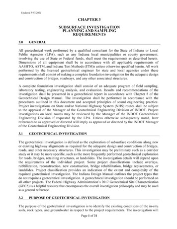
Instruments forMonitoringPore-Water PressureStandpipePiezometersPiezometers are the only instrument used to monitor pore-water pressure.There are two basic types of piezometers: Standpipe Piezometers Diaphragm piezometers (vibrating wire, pneumatic, or strain-gauge).The standpipe piezometer, sometimesreferred to as an open-hydraulic piezometeror a Casagrande piezometer, consists of aporous water-intake element connected to ariser pipe.Water enters the riser pipe through theintake element, which is normally sealed inthe borehole at a specified depth. As porewater pressure increases or decreases, thewater level inside the standpipe rises or falls.Readings are usually obtained with a waterlevel indicator, which provides a depth-towater measurement.ComponentsThe water intake element may be a filter or awell-screen, as shown above. The filter element is made of hydrophilic polyethylene orfused aluminum oxide, generally 12 to 24inches long with 60 to 70 micron pores.The riser pipe is 0.75 or 1-inch plastic pipe.If there is a chance that the standpipe piezometer readings will be automated in thefuture, choose a one inch or larger pipe thatwill accommodate a 3/4 inch diameter pressure transducer.The key feature of a standpipe piezometer isthe bentonite seal placed above the intakezone. This prevents water from other stratafrom entering the standpipe. Thus water inthe standpipe is controlled by pore-waterpressure at the intake zone.Advantages Limitations Riser PipeBentonite-Cement GroutWater Level produced bypore-water pressure atthe filter tipBentonite SealSand Intake ZoneFilter TipDirect measurement of water level. There are no buried “sensing” components.Readings require direct access to the top of the pipe. Slow response time in soils with low permeability.Guide to Geotechnical Instruments, 2004/11/247
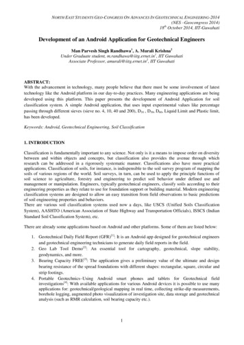
PneumaticPiezometersComponentsPneumatic PiezometerOperationThe pneumatic piezometer is operatedby gas pressure. In a typical installation, the piezometer is sealed in theborehole, and twin pneumatic tubesrun from the piezometer to a terminalat the surface where readings areobtained with a pneumatic indicator.The piezometer consists of a transducer body, tubing, and a portable indicator. The transducer body has a 50 micron filter, suitable for most applications. The tubing bundle contains two polyethylene tubes, one to carry gasto the transducer, the other to return excess gas. The portable indicatorcontains a pressure gauge and a tank of compressed nitrogen gas.The piezometer is installed in the sameway as a standpipe piezometer, with thetransducer sealed within a sand intakezone by a bentonite plug.To obtain a reading, the operator connects the input tube to a pneumatic indicator and directs a flow of gas to thepiezometer.Tubing to readoutBentonite-cement groutThe operator shuts off the gas when areturn flow is detected in the other tube.The operator then watches the pressuregauge and notes the pressure when thereading is stable. The time it takes for thereading procedure varies with the lengthof the tubing.Grout plugSand filterAdvantages Limitations Buried components are simple and do not need calibration Components are not affected by electrical transients. Fast response time in most soils.Requires operator who is careful and consistent. Takes longer to read than a standpipe or VW piezometer. Indicator must be recharged regularly with dry nitrogen gas. The use ofdry gas is important to keep tubing free of condensation.Guide to Geotechnical Instruments, 2004/11/248
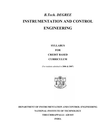
Vibrating WirePiezometersThe VW piezometer is a consists of apressure transducer and signal cable.Readings are obtained with a portablereadout or data logger. The transduceris available in 50, 100, 250, and 500 psiranges.There are two body styles, as shown inthe photo. The upper instrument is the standard body, and is suitable for allapplications. The lower instrument is a special push-in design used only insoft clays. Filters for both styles have a 50 micron pore-size and are suitablefor all applications. Signal cable contains four wires and should have ajacket made of polyurethane or polyethylene.VW PiezometerOperationThe VW piezometer can be installed without asand intake zone and bentonite seal. Instead, theentire borehole is backfilled with a bentonitecement grout. See installation notes for moreinformation.The vibrating wire principle states thattension in a wire is proportional to the square ofits natural frequency. The piezometer is designedso that pressure on its diaphragm controls the tension of the vibrating wire element inside.When a readout is connected to the signal cable, itsends an electric pulse to a coil that plucks thewire, causing it to vibrate at its natural frequency.A second coil picks up the vibration and returns afrequency reading to the readout.Calibration factors must be applied to the readingto obtain units of pressure. This may be done bythe readout or on a computer.Advantages Limitations Cable to readout or loggerBentonite-cement groutGrout plugIn grout-in installation,the plug is eliminated.Sand intake zoneIn grout-in installation,intake zone is eliminated.Simple grout-in installation procedure opens the possibility of same-holeinstallation of multiple piezometers or installation of piezometers withinclinometer casing. The VW piezometer provides rapid response in all types of soils. Suitable for unattended monitoring with a data logger.Calibrated component is buried (same as other electrical sensors). Must be protected from electrical transients in locations where lightningis common (same as other electrical sensors). VW sensors require data loggers and readouts with VW interfaces.Guide to Geotechnical Instruments, 2004/11/249
MultiLevelVW PiezometersThe multi-level VW piezometer is usedin series to monitor pore-water pressureat multiple zones in a borehole.The system combines standard VWpiezometers and PVC pipe. The piezometers are installed in-line with thePVC pipe. The assembled pipe controlsthe elevation and relative spacing of the piezometers. Signal cables run tothe surface through the PVC placement pipe.The entire assembly of pipe and piezometersis pushed into the borehole. e pipe controlsthe elevation and relative spacing of thepiezometers. It is assembled pushed into theborehole.When the components of the system are inplace, bentonite-cement grout is pumpedthrough the pipe to backfill the entire borehole, including the area surrounding eachpiezometer.When the grout cures, each piezometer isisolated from the zones above and below it,but is highly responsive to changes in porewater pressures at its own elevation.The multi-level piezometer shares the advantages and limitations of standard VW piezometers.VW piezometer with filter tippointing upwards to preventformation of air bubblesbehind the filter.Plastic housing holds piezometer onto a short length ofPVC pipe.PVC pipe provides a way tocontrol the precise installation depth of each piezometer.The pipe also serves as aprotective conduit for signalcables, preventing damagewhen auger or drill casing isremoved.Bentonite-cement groutisolates each piezometerfrom the zones above andbelow it. The piezometermeasures only local porewater pressure.Small 2.4" diameter ofhousing allows installationin a three-inch or largerborehole.Borehole is grouted throughthe same PVC pipe that carries cables.Guide to Geotechnical Instruments, 2004/11/2410
Choosing aPiezometerAll of the piezometers discussed here, whether standpipe, pneumatic, orVW, have the accuracy and resolution needed for good pore-water pressuremeasurements. The choice of a piezometer should be based on the factorssummarized in the table below. Items with * are explained in the text following the comparison table.PiezometerComparisonPiezometerResponse TimeStandpipeVWPneumaticRangeDepth of standpipe50, 100, 250, 500 psi180 psiResponse Time*SlowFastFastReading Time*MinutesSeconds5 minutes with 200feet of tubing.Longer times withlonger tubing.Readout*Water level indicator.Size and weightdepend on reelcapacity.Portable readout.Lightest, smallest.Portable readout.Large and heavybecause of internaltank.Remote Access*No. Reading isobtained at top ofstandpipe.Yes. Signal cable canbe run to remotereadout station.Yes. Tubing can berun to remote readout stationDataLog*NoYesNoMain AdvantagesSimplicity. Nothingto go wrong.Easy to read. Simplegrout-in installation.Remote access.Remote access.Not affect by electrical transients.Main LimitationsNo remote access.Long horizontal runsof cable should beprotected from electrical transients.Slow reading timeMain Cost ofInstallationBorehole.Components are theleast expensive ofany type of piezometer.Borehole.Components aremore expensivethan pneumatic orstandpipe.Borehole.Components are lessexpensive than VWpiezometers.Response time is relevant mainly in cohesive soils, such as clays, that do noteasily release their water. When pore-water pressure changes, some volumeof water flows into or out of the piezometer until an equilibrium is established between the pore-water pressure in the soil and the water in thepiezometer. The time required for this equilibrium to occur is called thepiezometer’s response time.Factors affecting response time are the hydraulic conductivity of the soiland the volume of water that must flow into or out of the piezometer. Diaphragm piezometers require less water and therefore have faster responsetime. Standpipe piezometers are intrinsically slower than diaphragm piezometers because the standpipe requires a larger volume of water. For example, a small-diameter 3/4-inch standpipe requires an inflow of 240 ml ofGuide to Geotechnical Instruments, 2004/11/2411
water to show a 1 psi change in pore-water pressure. A VW piezometer,which has a very sensitive diaphragm, requires an inflow of only 0.00002 ml(12 million times smaller) to show the same 1 psi change. In highly permeable soils where water is readily available, the difference in response timesmay be insignificant. However, in clays and other soils where permeabilityis very low, the response times will be very different, making the VW piezometer or some other electric piezometer the only useful choice.In certain conditions, the response time of a diaphragm piezometer can beslowed if there is an air bubble between the filter and the diaphragm. Theair bubble must deform (change volume) before it can transmit the pressureof the water, and this requires a greater inflow or outflow of water than ifthere were no air bubble. In saturated soils with high permeability, the presence of a bubble has little effect, since water is in good supply, and the bubble is easily compressed. In tight soils, such as clays, response time may beslowed by the presence of a bubble, because the free water needed to compress the bubble, is scarce.Remote AccessMeasuring the water level in standpipe piezometers requires direct access tothe top of the pipe. If regular and continued access is not possible, then adiaphragm piezometer, which can be operated from a remote readout station, is the only choice.Reading TimeIn general, pneumatic piezometers take longest to read. Standpipes canoccasionally present problems if they are not installed straight or if falsetriggering occurs due to organics grow on standpipe walls. VW sensors cannormally be read in seconds.ReadoutReadout size and weight become an issue because field technicians oftentake several readouts with them. The pneumatic indicator is the largest andheaviest. Its internal tank requires regular refills. The VW indicator is thesmallest and lightest. The size and weight of the water level indicatordepends on the quantity of cable on its reel. All three readouts use batteries,which must be changed from time to time.Data LoggingData loggers allow readings to be taken without a technician present. Moreimportant, data loggers allow many more readings to be taken, sometimesrevealing trends that otherwise would go unnoticed. VW sensors are suitable for data logging. However, to read VW sensors, the data logger musthave a VW interface. Pneumatic piezometers can be automated, but this is acostly undertaking and is therefore quite rare. Sometimes standpipes areadapted to data loggers by installation of a diaphragm piezometer withinthe standpipe. The response time for the converted standpipe will remainthe same, since the pipe must still fill with water.Guide to Geotechnical Instruments, 2004/11/2412
Note on FiltersSpecifications sometimes mention the importance of saturating piezometerfilters. Standpipe and diaphragm piezometers are usually equipped with astandard filter that has 50 to 60 micron pores. These filters become saturated when immersed in water without any elaborate saturation procedure.Saturation procedures are important for special filters with smaller pores,called high air entry filters. However, these filters are not appropriate forstandpipe or diaphragm piezometers.The high air entry filter relies on the surface tension of water in its pores tosustain a pressure difference between air and water on the filter surface.This keeps air out of the measuring system (which is a fluid) and allowsmeasurement of matrix soil suction (negative pore-water pressure) that ispresent in non-saturated soils. The high air entry effect is operative onlywhen the filter is saturated with water. When water drains out of the filter,the high-air entry effect disappears.Only one type of piezometer, the hydraulic piezometer, is capable of maintaining saturation of the filter in non-saturated soils. Diaphragm piezometers and standpipe piezometers do not normally have this capability, andtherefore should not be specified with high air entry filters.Guide to Geotechnical Instruments, 2004/11/2413
Monitoring Lateral DeformationLateral DeformationMeasurements of lateral deformation help engineers to: Evaluate the stability of slopes and embankments. Determine the need and timing for corrective measures. Verify the performance and safety of structures such as retaining wallsand embankments.Landslides,Cuttings,and Embankments Monitor stability of slope,cut, or embankment.Ground ProfilePrior to SlipGround ProfileAfter SlipDetect shear zones andhelp determine whethershear is planar or circular.Slip PlaneGround Level Determine whether movement is constant, accelerating, or slowing.Slip PlaneOriginal Ground LevelFinished Ground LevelPotential Slip PlanesPotential Slip PlaneSoft SoilFirm SoilGuide to Geotechnical Instruments, 2004/11/2414
Retaining Walls Monitor deformation ofsoil behind retaining wall. Check for rotation ofretaining wall.DrainRETW.cdrDiaphragm Wall or SheetPile Wall Check that deflections ofwall are within designlimits. Check for ground movement that may affect adjacent buildings. Inclinometerin WallGround AnchorVerify that struts andground anchors and performing as planned.EXC.cdrRock Slides andRock Abutments Monitor the magnitudeand rate of movements inrock masses.Pile Tests Monitor deformation oflaterally loaded pile.Ground Level Warn of impendingfailure.Soft SoilPILE.cdrGuide to Geotechnical Instruments, 2004/11/2415
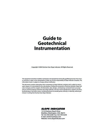
InclinometersInclinometerComponentsThe primary instrument for monitoring lateral, subsurface deformations isthe inclinometer. There are two types of inclinometer systems: the portable,traversing probe system and the dedicated, in-place sensor system. Bothsystems require the use of inclinometer casing. Inclinometer casing is used with both types ofinclinometer. This special-purpose, groovedpipe is installed in a borehole that passesthrough suspected zones of movement. It canalso be embedded in fill, cast into concrete, orattached to structures.Inclinometer casing provides access for theinclinometer probe, allowing it to obtain subsurface measurements. Grooves inside thecasing control the orientation of the probeand provide a surface from which repeatablemeasurements can be obtained. The traversing probe system consists of a portable wheeled probe,graduated control cable, and a portable readout. With this system, theoperator makes a survey of theborehole, taking tilt readings attwo-foot intervals, from the bottomto the top of the casing to the top. The probe is then rotated 180 degreesand a second survey is obtained. The resulting data provides a detailedprofile of the casing. If ground movement occurs, subsequent surveys willreveal changes in the profile. These changes can be plotted to determinethe magnitude, depth, direction, and rate of ground movement. In-place inclinometer systems areinstalled when continuous monitoring is required for construction control or safety. The in-place systemconsists of one or more dedicatedsensors connected to a data logger.The sensors are positioned to spanthe zones where deformation is likelyto occur (a traversing probe systemmay be used to detect such zones).Guide to Geotechnical Instruments, 2004/11/2416
Choosing betweenTraversing andIn-Place SystemsComparisonFull Profile An optional component of an inclinometer system is software for data reductionand graphing. Inclinometers generatemore data than do other types of sensors.A single survey may generate severalhundred data points. Over time, tens ofthousands of data points are manipulated, reduced, graphed, and archived.In-place inclinometer systems connected to data loggers generate evenmore data. With such systems, near-realtime processing is usually a requirementas is software that shows the location ofthe sensors, the readings, alarm status, and trend plots. Another optional component is the spiral sensor, which is used to determine if the casing was twisted during installation. Spiral surveys may beappropriate when the installation is very deep or when inclinometerreadings indicate movement in unlikely directions.Both types of inclinometer offer sufficient resolution and accuracy for geotechnical purposes. The choice between the traversing probe system andthe in-place system should be based on other factors, summarized below:ITraversing SystemIn-Place SystemFull Profile*YesNoReading Time45 minutes per 100 feetSecondsRemote Access*NoYesData Logging*NoYesMain AdvantagesLeast expensive way to monitor many installations.Only way to obtain near realtime readings and remotereadings.Main LimitationsProbe cable and readout arebulky and heavy. Readingtakes time.Long horizontal runs ofcable must be protectedfrom electrical transients.Installation CostsBorehole for inclinometercasing is the main cost.Borehole for inclinometercasing is the main cost. However, sensors and logger system can cost nearly as much.On-Going CostsSending a technician to readthe installation is main cost.Few on-going costs.The traversing probe system yields a detailed survey of the entire length ofthe inclinometer casing. This allows identification of multiple shear zonesand provides a context for understanding deformations in those zones.Guide to Geotechnical Instruments, 2004/11/2417
In contrast, the in-place system provides a narrow sample of the installation. Proper positioning is critical. Often a traversing probe is used firstuntil the shear zone has been ident
Construction Control Instruments are used to monitor the effects of construction. Instrument data can help the engineer determine how fast construction can proceed without the risk of failure. Quality Control Instrumentation can be used both to enforce the quality of workmanship on a proj