Transcription
NCAT Report 01-02AS-BUILT PROPERTIES OFEXPERIMENTAL SECTIONS ONTHE 2000 NCAT PAVEMENT TESTTRACKByR. Buzz PowellApril 2001277 Technology Parkway Auburn, AL 36830
AS-BUILT PROPERTIES OF EXPERIMENTAL SECTIONS ON THE 2000NCAT PAVEMENT TEST TRACKByR. Buzz PowellTest Track ManagerNational Center for Asphalt TechnologyAuburn University, AlabamaNCAT Report 01-02April 2001
DISCLAIMERThe contents of this report reflect the views of the authors who are solely responsible forthe facts and the accuracy of the data presented herein. The contents do not necessarily reflectthe official views and policies of the National Center for Asphalt Technology of AuburnUniversity. This report does not constitute a standard, specification, or regulation.-i-
PowellAS-BUILT PROPERTIES OF EXPERIMENTAL SECTIONS ON THE 2000 NCATPAVEMENT TEST TRACKR. Buzz PowellBACKGROUNDAn experimental facility is now operational near the campus of Auburn University that will beutilized by governmental agencies nationwide to streamline the practical application of researchdesigned to extend the life of flexible pavements. Managed by the National Center for AsphaltTechnology (NCAT), the Pavement Test Track provides a unique opportunity for sponsors toanswer specific questions related to flexible pavement performance in a full scale, acceleratedmanner where results do not require laboratory scale extrapolations or lifelong fieldobservations.Experimental sections on the Pavement Test Track are cooperatively funded by externalsponsors, most commonly state DOT’s, with subsequent operation and research managed byNCAT. Forty-six different flexible pavements have been installed at the facility (26 in thetangents and 20 in the curves), each at a length of approximately 200 feet. The underlyingstructural buildup is exactly the same for every section, where sponsors typically chose to placetheir research mixes at a total thickness of 4 inches to facilitate direct comparisons with othersponsors’ results. Materials and methods unique to section sponsors were imported duringconstruction to maximize the applicability of results. A design lifetime of truck traffic (10million equivalent single axle loadings, or ESALs) began in 2000 with a scheduled completiondate of 2002.Unlike conventional efforts on public roadways, research at the NCAT Pavement Test Track isconducted in a closed-loop facility where axle loadings are precisely monitored andenvironmental effects are identical for every mix. An array of surface parameters (smoothness,rutting, cracking, etc.) are monitored weekly as truck traffic accumulates to facilitate objectiveperformance analyses. State DOT’s typically have to wait 10 to 15 years to obtain less reliableresults in full-scale field studies on public roadways.Sponsors typically fund research on two sections so they can compare life cycle costs ofcommon paving alternatives. In this manner, they can rationally manage the public’s investmentin flexible pavements by choosing mixes that cost less over the life of the structure. For example,it is unwise to spend less on construction if the cheaper construction alternative results in asubstantially higher life cycle cost. In addition to comparing alternatives for sponsors, NCAT isresponsible for guiding the overall effort in a direction that will address policy issues for thehighway industry as a whole. For example, can fine-graded mixes perform as well as coarsegraded mixes if both are proportioned in a manner consistent with established design criteria?The Pavement Test Track (referred to occasionally hereafter as the Track) is the result ofindustry and government committing to work together to improve the quality of flexiblepavement performance, thus maximizing the taxpayers’ investment in America’s roadwaytransportation infrastructure. The facility is expected to clarify the relationship between methodsand performance such that design and construction policy in the future can be objectively guidedby life cycle costs. Additionally, the broad range of methodologies and materials utilized to buildthe Track provides a proving ground for laboratory methods intended to predict the performanceof pavements in the field.1
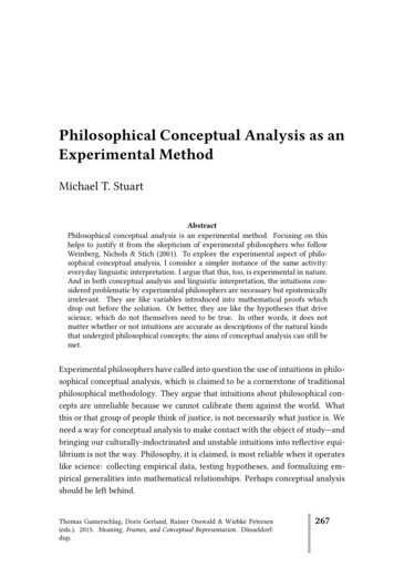
PowellINTRODUCTIONIt is useful to fully document the installation of experimental mixes for several reasons. Sponsorswere invited to travel to the Track to oversee the construction of their sections, at which timeboth laboratory and field data were presented to them in a timely manner so they could makeeducated decisions regarding quality control and ultimate acceptance. The nature of constructionrequired that these data be collected and digested in an expedited, concise manner; consequently,it is important to provide sponsors with a detailed view of their research following thecompletion of more rigorous testing.Additionally, this effort will serve to provide other researchers with information necessary toreplicate the materials, mixes, and construction efforts in any supplemental activities that mayserve to extend the benefits of this project beyond the original intent of the sponsoring entities.For example, it may be possible to run identically proportioned materials through an unrelatedproduction facility and replicate the effort in other locales.To address these needs, this document is intended to summarize the as-built condition ofexperimental sections constructed at the NCAT Pavement Test Track. A summary of informationthat may be relevant in assessing and comparing section performance is provided as Appendix A,where the location of referenced sections may be identified using Figure 1. Experimental mixesare presented therein chronologically in order of completion date.Figure 1. NCAT Pavement Test Track LayoutMATERIALSSponsors were encouraged to consider research efforts in other sections in developing theircomparison studies. Most sponsors chose to ship in their own unique local aggregates whilerelying upon the “Track stock” asphalt binder. Appendix B is included herein to generallysummarize the nature of the overall experiment and emphasize the relevance of the performancein sections constructed with similar materials.2
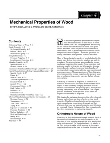
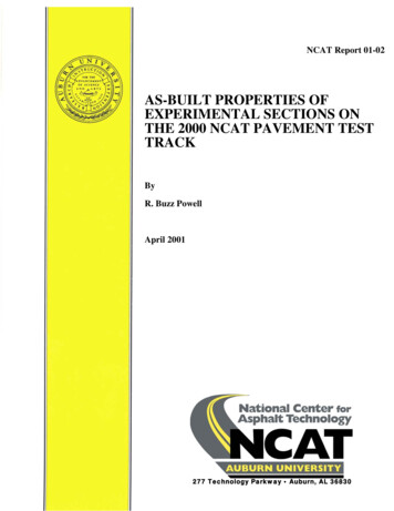
PowellFor example, sponsors who elected to build sections with granite aggregates can compare theperformance of fine-graded versus coarse-graded versus dense-graded aggregate blends, 3/8versus ½ inch nominal maximum aggregate size, neat versus SBR versus SBS modified asphaltbinders, Superpave versus Stone Matrix Asphalt (SMA) design methodologies, etc. Specificsource locations of aggregate fractions are not revealed herein to protect the anonymity andobjectivity of the research; however, the effect of aggregate source and quadrant placement onthe Track (curve versus tangent) must be considered when interpreting final results.A single source was used to supply the neat (PG 67-22) and SBS modified (PG 76-22) asphaltbinders; however, it was determined that this supplier could not guarantee that the needed SBRmodified (PG 76-22) binder would arrive at the onsite plant at the proper grade (when shipped inuncirculated tankers). Consequently, the neat/SBS supplier shipped unmodified material to asecond, more local supplier who added their SBR modifier then delivered the final product to theplant site under certification for quality. Near the end of the project, an SB modified (PG 70-28)asphalt binder was also utilized for the production of two adjacent sections.PROPORTIONINGLaboratory job-mix formulas were used as a starting point when each mix was trial run throughthe plant for the first time, except that actual stockpile gradations were used to make subtleadjustments to the bin percentages wherever possible. Stockpile moisture contents weremeasured daily on any mixes that were scheduled for production to minimize the effect on plantoperations and resulting final mix proportions. A portable double drum plant (presented asFigure 2) was temporarily located onsite to produce mix exclusively for Track construction withminimal haul times.Figure 2. Onsite Double Drum Asphalt Plant Used to Produce All Track MixA sufficient quantity of both coated and uncoated material was wasted on either end of eachproduction run so that a meaningful sample could be recovered and tested in the onsitelaboratory. Representative samples were recovered using conventional shovel sampling methods,an automated robotic sampling device (presented as Figure 3), and an automated cold belt sweep3
PowellFigure 3. Sampling Representative Mix with Automated Robotic Samplersampler. A mechanical hot-mix sample splitting device was used in the onsite laboratory toavoid rapid cooling associated with conventional quartering and its subsequent effect onlaboratory sample compaction temperatures.Nuclear asphalt content measurements were utilized to supplement extractions via biodegradablesolvent and ignition furnace. Conventional gradations with washed fines were then run onuncoated aggregate blends. Volumetric samples were prepared using the Superpave gyratorycompactor (SGC) for the majority of the Track, with a portable Texas gyratory being used for thesingle Hveem mix and a Marshall hammer used for the SMA’s. Both laboratory density androadway compaction were compared to theoretical maximum values obtained via the Ricemethod to compute percent compaction and air voids. Drybacks were utilized for sectionscontaining absorptive materials.Plant settings were then adjusted based upon laboratory test data and either another trial run wasdeemed necessary or the final plant-run job-mix formula was established. Whenever practical,trial mix was placed on Lee Road 151 (the local, previously unpaved road leading into thefacility) so that sponsor representatives could weigh placement and compaction into theirdecision making process. Following the determination of the final job-mix formula, productionof mix for placement on the Track surface was authorized.CONSTRUCTIONConstruction of the actual test sections was allowed to begin after sponsors were satisfied withtheir trial mix results. Enough mix was produced in a continuous run to accommodate placementof both the inside and outside lanes of a single lift to minimize the amount of wasted materialrequired to obtain stable production. Since most of the equipment was relatively cool due to thenature of the sporadic production runs, the plant was typically allowed to produce mix at slightlyunder the high end of the allowable temperature range (which is approximately 350/F to protectthe binder from rapid aging).Two 24-ton haul trucks were loaded and driven the short distance to the location of test sectionplacement, with the balance of the plant run being kept in the integrated 65-ton surge bin. Pavingwas allowed to begin only when both trucks were lined up and ready to discharge into the4
Powellmaterial transfer device (MTD). Generally, the inside lane was paved first to establish a rollingpattern and was then utilized for destructive coring so that corrected nuclear gauge testing couldbe done non-destructively in the research (outside) lane.Pavers were preheated and raised slightly off the surface of the previously placed mat usingmetal spacer plates of varying thickness. When a steady flow of mix was available from theMTD, the paver pulled off the joint and began its slow movement to the far end of the section. Inevery case, it was required that placement operations proceed in the direction of traffic (counterclockwise). At the far end of the joint, the paver overran the distance requirement by 5 to 10 feetand lifted up the screed. This allowed the paver to be driven clear of the immediate constructionzone. If the inside lane had just been completed, the paver was backed up and positioned onmetal plates in anticipation of pulling the outside (research) lane. Typically, two pavers(conventional and gravity feed, presented in Figures 4 and 5) were used to pave a section suchthat the first unit paved the inside lane and the second unit paved the outside lane.A backhoe was then used to slice into the mound of material that had been left in place at the endof the run when the screed was lifted. This excess material was pulled back and pushed off theside of the shoulder for later cleanup and removal. With a cleanly defined fresh mat at theFigure 4. Typical Dual Lane Paving Operation Using MTDFigure 5. Paving Equipment Typically Used to Place Mixes in Outside Lane5
Powellfar end of the run, the first roller was then allowed to drive onto the uncompacted inside lane.When the roller reached the far end of the mat, it simply ramped down the overplaced mix andreversed direction. Relative increases in density were monitored in the inside lane to identify thebreakpoint in the compaction operation, which was used to establish the roller pattern in theoutside (research) lane. Vibratory steel-wheeled rollers (Figure 6) were used for breakdownrolling, a pneumatic rubber-tired roller (Figure 7) was used as necessary for intermediate rolling,and the vibratory steel-wheeled roller was used in static mode for finish rolling.Figure 6. One of Two Vibratory Steel-Wheeled Rollers Utilized for CompactionConcurrently, the MTD was advanced slightly and boomed over to accommodate dumping twoto three tons of blended mix into a front-end loader (as presented in Figure 8). This materialwould be utilized for the fabrication of numerous research specimens that would later be used forlaboratory performance testing, and could not be discharged from the MTD until its blendingchamber had been filled via a return visit from one of the two haul trucks. When filled withmaterial that was representative of the new mat, the front-end loader was driven back to theonsite laboratory where material was sampled via shovel and stored in buckets for staged heatingand sample compaction.In compacting the typical experimental section, four coverages with the vibratory steel-wheeledroller were accomplished with 12 passes. The first pass was begun just as the paver lifted up andpulled away at the far end of the mat. Since the vast majority of experimental mixes containedmodified asphalt binder, the average temperature documented behind the paver prior to initialcompaction was 318 F. Generally, rollers were operated at high frequency and high amplitude;however, the mats were monitored closely to avoid white-topping and related damage to mixaggregates. The pneumatic rubber-tired roller was utilized in several instances where a tenderzone was encountered in intermediate temperatures. Finally, steel-wheel rollers were utilized instatic mode to accomplish finish rolling, which typically consisted of four coverages via 12passes with the mat at or just under 175 F.6
PowellFigure 7. Pneumatic Rubber-Tired Roller Utilized for CompactionFigure 8. Obtaining Large Quantity of Representative Mix for Research7
PowellOnce the placement and compaction operation for both lanes had been completed, a straightedgewas used to identify a distance from the far end of the mat that would most likely accommodate asmooth transition between sections. A chalk line was then popped at this distance and a masonrysaw was used to cut a clean vertical face in the new mat. Lastly, a backhoe was used to pull allexcess material off the shoulder for later cleanup and removal.The Alabama Department of Transportation (ALDOT) conventional smoothness specificationwas utilized to review and accept the quality of joint construction for every section on the Track.Although all joints passed their ¼ inch deviation tolerance using a 15 ft straightedge, it was laterdecided (based upon objective smoothness analyses) that diamond grinding should be utilized toenhance the rideability of 11 of the 46 total construction joints.VERIFICATIONThe Track was constructed via an ALDOT administered construction contract with NCATserving as the acceptance authority on the production and placement of experimental mixes;consequently, ALDOT field methods were utilized to generate quick laboratory test data thatcould be used by sponsors to make quality control assessments and acceptance decisions. Morebroadly accepted methods were utilized after construction to verify the final section propertiesthat would be made available for publication.Specifically, reflux testing (as presented in Figure 9) and calibrated ignition furnace testing wasutilized to determine the asphalt content of samples that were collected during construction andsaved for post-processing. Mixes with highly modified binder contents and fiber stabilizer weresubjected to low-speed centrifuge testing. Subsequent binder-dust separations wereaccomplished via high-speed centrifuge. Lastly, particle size distributions of then uncoatedaggregate blends were determined.SUMMARYThe first lower lift was placed in the second section of the east curve on March 21, 2000. Workproceeded in a counter-clockwise manner around the Track through the spring and into summer.The east curve was completed, followed by the north tangent, the west curve, and finally thesouth tangent. The last upper lift was placed on the first section of the east curve on July 14,2000.Based upon a survey of elevations between the wheelpaths before and after construction, theaverage thickness of the completed experimental sections is 4.1 inches, with an averagethickness standard deviation within each section of 0.1 inches. The target thickness for sectionsincluded in this evaluation was 4.0 inches. It should be noted that 2 sections placed at a targetthickness of 3.6 inches and 2 sections placed at a target thickness of 3.0 inches were not includedin this analysis.After approximately 1.6 million ESALs had been applied, or 16 percent of the 10,000,000 ESALtotal requirement, no noticeable distresses had been observed. An extrapolation of this progressindicates that the 10,000,000 ESAL total should be completed by November of 2002.Numerous publications and activities are planned throughout the course of the research in aneffort to inform sponsors on the status of their experimental mixes both on the Track and in thelaboratory:8
PowellFigure 9. Reflux Extraction Verification Testing of Construction Samples1. Initially, a concise document tentatively entitled “An Overview of Construction at theNCAT Pavement Test Track” that describes the equipment and methods utilized toconstruct experimental sections will be useful in conveying construction experiencesto the pavement construction community. It is anticipated that this document will becompleted by the end of April in 2001;2. Subsequently, a paper providing the background and development of the Track willbe especially useful when paired with quality control data and a summary of theexperimental design. Tentatively entitled “A General Overview of Research Efforts atthe NCAT Pavement Test Track,” it is anticipated that this project overview will alsobe delivered by the end of April in 2001;3. In anticipation of the differentiation in performance that may begin with the intenseheating of the mat in the late spring and early summer, an onsite meeting was plannedfor June 11-12 of 2001. Funds are allocated to bring a single representative from eachsponsoring entity to Auburn University with all expenses paid by the pooled fund.Additional representatives may attend with prior notification if the cost is born by thesponsor. Specific details will be provided on this meeting as the date approaches;4. Soon after the June onsite meeting, sponsors will be provided with a summary oflaboratory testing that will ultimately be compared to field performance ofexperimental sections. Basic material property testing (e.g. shear strengthmeasurements) will be presented as well as torture testing (e.g. loaded wheel testing)to define mix performance in the laboratory. It is anticipated that this formaldocument will be submitted to section sponsors in mid-July of 2001. The tentativetitle for this publication is “Laboratory Performance Testing for the NCAT PavementTest Track”;9
Powell5. Upon the completion of approximately one year of traffic, a summary of sectionperformance will be provided and paired with the previously published laboratorypredictions to provide an early indication of the suitability of laboratory methods topredict field performance. It is anticipated that this document, tentatively titled “AProgress Report After One Year of Traffic on the NCAT Pavement Test Track,” willbe delivered in October of 2001;6. Following the completion of truck traffic, an interim report will be distributedsummarizing the surface condition of experimental sections. This document willlikely be titled “A Report of Post-Traffic Surface Condition on the NCAT PavementTest Track” and is intended to keep sponsors informed regarding ultimate sectionfield performance while awaiting final results from the concurrent post-mortem study.It is anticipated that this document will be distributed approximately two months afterthe successful application of 10,000,000 ESALs near the end of the project;7. Ultimately, a report tentatively titled “The Final Report for Initial Research Efforts atthe NCAT Pavement Test Track” will be provided to section sponsors as a summarypublication to consider the results of post-mortem studies and compare the ultimatefield performance of hot-mix design and construction methodologies. Additionally,the suitability of using numerous laboratory performance evaluation methods topredict full-scale performance in the field will be presented. It is anticipated that thisfinal document will be delivered in July of 2003; and8. Interested parties are encouraged to obtain informal updates at any time via theInternet. The project web site, accessed at www.pavetrack.com, has interactive pagesfor general information, section construction properties, laboratory and fieldperformance, and links to sponsors and suppliers. The information contained inAppendix A may be viewed for each section by clicking the interactive Track layouton the construction page.10
PowellAppendix ASummary of Final Section Properties11
PowellSection E2Laboratory DiaryConstruction DiaryGeneral Description of Mix and MaterialsRelevant Conditions for ConstructionDesign Method:Compactive Effort:Binder Performance Grade:Modifier Type:Aggregate Type:Gradation Type:Superpave100 gyrations67-22NAGraniteBRZCompletion Date:Tuesday, April 11, 200024 Hour High Temperature (F):7624 Hour Low Temperature (F):5024 Hour Rainfall (in):0.00Lift Type:dualDesign Thickness of Test Mix (in):4.0Avg. Lab Properties of Plant Produced MixSieve Size:1"3/4"1/2"3/8"No. 4No. 8No. 16No. 30No. 50No. 100No. 200% Passing:1001009674412922181274.1Asphalt Binder Content:Compacted Pill Bulk Gravity:Theoretical Maximum Gravity:Computed Air Voids:4.7%2.4342.5052.8%Plant Configuration and Placement DetailsComponent:Liquid Binder SettingGranite7Granite89GraniteM10GraniteW10% Setting:4.8%48.0%17.0%20.0%15.0%Approximate Length (ft):213Surveyed Thickness of Section (in):4.2Std Dev of Section Thickness (in):0.2Type of Tack Coat Utilized:CQS-1hTarget Tack Application Rate:0.03 gal/syAvg Mat Temperature Behind Paver (F): 297Average Section Compaction:94.7%General Notes:1) Mixes are listed chronologically in order of completion date (i.e., construction began with E2 and ended with E1).2) Sections are referenced by quadrant and sequence number, where “E2” refers to section 2 of the east quadrant.3) “dual” lift type indicates that the lower and upper lifts were constructed with the same experimental mix.4) The total thickness of all experimental sections is 4 inches by design, with the exception of S8, S9, S10, S11.5) ARZ, TRZ, and BRZ refer to gradations intended to pass above, through, and below the restricted zone.6) SMA and OGFC refer to stone matrix asphalt and open-graded friction course, respectively.12
PowellSection E3Laboratory DiaryConstruction DiaryGeneral Description of Mix and MaterialsRelevant Conditions for ConstructionDesign Method:Compactive Effort:Binder Performance Grade:Modifier Type:Aggregate Type:Gradation Type:Superpave100 gyrations76-22SBRGraniteBRZCompletion Date:Tuesday, April 11, 200024 Hour High Temperature (F):7624 Hour Low Temperature (F):5024 Hour Rainfall (in):0.00Lift Type:dualDesign Thickness of Test Mix (in):4.0Avg. Lab Properties of Plant Produced MixSieve Size:1"3/4"1/2"3/8"No. 4No. 8No. 16No. 30No. 50No. 100No. 200% Passing:1001009473412923181274.2Asphalt Binder Content:Compacted Pill Bulk Gravity:Theoretical Maximum Gravity:Computed Air Voids:4.8%2.4192.5194.0%Plant Configuration and Placement DetailsComponent:Liquid Binder SettingGranite7Granite89GraniteM10GraniteW10% Setting:4.7%48.0%19.0%18.0%15.0%Approximate Length (ft):189Surveyed Thickness of Section (in):4.1Std Dev of Section Thickness (in):0.3Type of Tack Coat Utilized:CQS-1hTarget Tack Application Rate:0.03 gal/syAvg Mat Temperature Behind Paver (F): 325Average Section Compaction:93.5%General Notes:1) Mixes are listed chronologically in order of completion date (i.e., construction began with E2 and ended with E1).2) Sections are referenced by quadrant and sequence number, where “E2” refers to section 2 of the east quadrant.3) “dual” lift type indicates that the lower and upper lifts were constructed with the same experimental mix.4) The total thickness of all experimental sections is 4 inches by design, with the exception of S8, S9, S10, S11.5) ARZ, TRZ, and BRZ refer to gradations intended to pass above, through, and below the restricted zone.6) SMA and OGFC refer to stone matrix asphalt and open-graded friction course, respectively.13
PowellSection E4Laboratory DiaryConstruction DiaryGeneral Description of Mix and MaterialsRelevant Conditions for ConstructionDesign Method:Compactive Effort:Binder Performance Grade:Modifier Type:Aggregate Type:Gradation Type:Superpave100 gyrations76-22SBSGraniteBRZCompletion Date: Wednesday, April 12, 200024 Hour High Temperature (F):7724 Hour Low Temperature (F):5124 Hour Rainfall (in):0.00Lift Type:dualDesign Thickness of Test Mix (in):4.0Avg. Lab Properties of Plant Produced MixSieve Size:1"3/4"1/2"3/8"No. 4No. 8No. 16No. 30No. 50No. 100No. 200% Passing:1001009575422923181384.6Asphalt Binder Content:Compacted Pill Bulk Gravity:Theoretical Maximum Gravity:Computed Air Voids:4.7%2.4162.5123.8%Plant Configuration and Placement DetailsComponent:Liquid Binder SettingGranite7Granite89GraniteM10GraniteW10% Setting:4.7%48.0%19.0%18.0%15.0%Approximate Length (ft):204Surveyed Thickness of Section (in):4.1Std Dev of Section Thickness (in):0.1Type of Tack Coat Utilized:CQS-1hTarget Tack Application Rate:0.03 gal/syAvg Mat Temperature Behind Paver (F): 321Average Section Compaction:93.8%General Notes:1) Mixes are listed chronologically in order of completion date (i.e., construction began with E2 and ended with E1).2) Sections are referenced by quadrant and sequence number, where “E2” refers to section 2 of the east quadrant.3) “dual” lift type indicates that the lower and upper lifts were constructed with the same experimental mix.4) The total thickness of all experimental sections is 4 inches by design, with the exception of S8, S9, S10, S11.5) ARZ, TRZ, and BRZ refer to gradations intended to pass above, through, and below the restricted zone.6) SMA and OGFC refer to stone matrix asphalt and open-graded friction course, respectively.14
PowellSection E5Laboratory DiaryConstruction DiaryGeneral Description of Mix and MaterialsRelevant Conditions for ConstructionDesign Method:Compactive Effort:Binder Performance Grade:Modifier Type:Aggregate Type:Gradation Type:Superpave100 gyrations76-22SBSGraniteTRZCompletion Date:Thursday, April 13, 200024 Hour High Temperature (F):7524 Hour Low Temperature (F):5124 Hour Rainfall (in):0.00Lift Type:dualDesign Thickness of Test Mix (in):4.0Avg. Lab Properties of Plant Produced MixSieve Size:1"3/4"1/2"3/8"No. 4No. 8No. 16No. 30No. 50No. 100No. 200% Passing:1001009883544030241695.1Asphalt Binder Content:Compacted Pill Bulk Gravity:Theoretical Maximum Gravity:Computed Air Voids:5.1%2.4072.5003.7%Plant Configuration and Placement DetailsComponent:Liquid Binder SettingGranite7Granite89GraniteM10GraniteW10% Setting:5.0%33.0%23.0%24.0%20.0%Approximate Length (ft):201Surveyed Thickness of Section (in):4.2Std Dev of Section Thickness (in):0.2Type of Tack Coat Utilized:CQS-1hTarget Tack Application Rate:0.03 gal/syAvg Mat Temperature Behind Paver (F): 317Average Section Compaction:92.7%General Notes:1) Mixes are listed chronologically in order of completion date (i.e., construction began with E2 and ended with E1).2) Sections are referenced by quadrant and sequence number, where “E2” refers to section 2 of the east quadrant.3) “dual” lift type indicates that the lower and upper lifts were constructed with the same experimental mix.4) The total thickness of all experimental sections is 4 inches by design, with the exception of S8, S9, S10, S11.5) ARZ, TRZ, and BRZ refer to gradations intended to pass above, through, and below the restricted zone.6) SMA and OGFC refer to stone matrix asphalt and open-graded friction course, respectively.15
PowellSection E6Laboratory DiaryConstruction DiaryGeneral Description of Mix and MaterialsRelevant Conditions for ConstructionDesign Method:Compactive Effort:Binder Performance Grade:Modifier Type:Aggregate Type:Gradation Type:Superpave100 gyrations67-22NAGraniteTRZCompletion Date:Thursday, April 13, 200024 Hour High Temperature (F):7524 Hour Low Temperature (F):5124 Hour Rainfall (in):0.00Lift Type:dualDesign Thickness of Test Mix (in):4.0Avg. Lab Properties of Plant Produced MixSieve Size:1"3/4"1/2"3/8"No. 4No. 8No. 16No. 30No. 50No. 100No. 200% Passing:1001009681523728221584.3Asphalt Binder Content:Compacted Pill Bulk Gravity:Theoretical Maximum Gravity:Computed Air Voids:5.0%2.4112.5103.9%Plant Configuration and Placement DetailsComponent:Liquid Binder SettingGranite7Granite89GraniteM10GraniteW10
AS-BUILT PROPERTIES OF EXPERIMENTAL SECTIONS ON THE 2000 NCAT PAVEMENT TEST TRACK R. Buzz Powell BACKGROUND An experimental facility is now operational near the campus of Auburn University that will be utilized by governmental agencies nationwide to streamline the practical application of research designed to extend the life of flexible pavements.