Transcription
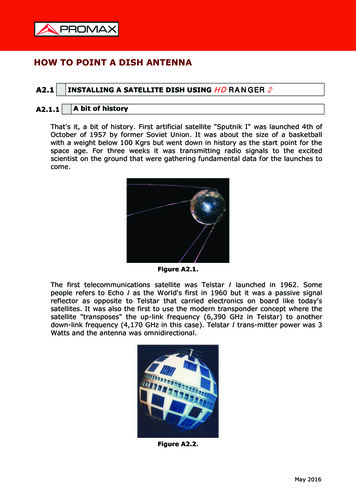
HOW TO POINT A DISH ANTENNAA2.1A2.1.1INSTALLING A SATELLITE DISH USING HD RANGER 2A bit of historyThat's it, a bit of history. First artificial satellite "Sputnik I" was launched 4th ofOctober of 1957 by former Soviet Union. It was about the size of a basketballwith a weight below 100 Kgrs but went down in history as the start point for thespace age. For three weeks it was transmitting radio signals to the excitedscientist on the ground that were gathering fundamental data for the launches tocome.Figure A2.1.The first telecommunications satellite was Telstar I launched in 1962. Somepeople refers to Echo I as the World's first in 1960 but it was a passive signalreflector as opposite to Telstar that carried electronics on board like today'ssatellites. It was also the first to use the modern transponder concept where thesatellite "transposes" the up-link frequency (6,390 GHz in Telstar) to anotherdown-link frequency (4,170 GHz in this case). Telstar I trans-mitter power was 3Watts and the antenna was omnidirectional.Figure A2.2.May 2016
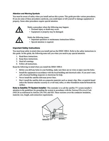
The antenna used to receive the test transmission from Telstar I was a huge horninside a bubble radome 48 metres high. Only four decades later we have brokenall records and we have high power DBS geostationary satellites carrying a lot ofdigital transponders on board and we start to worry about space junk havingthousands of satellites in orbit, plenty of them beyond its useful life. Satellitesuse highly efficient directional antennas and very high transmitters power, digitaltransponders, meaning in plain words that we can receive hundreds of TVchannels with a small, fix, cheap, 60 cm dish.Figure A2.3.Modern broadcast satellites use geostationary orbits. This simply means thatthey could be seen from the ground hunging in the sky at the same exactposition all the time and therefore receiving signals from them does not requirecomplex steering systems. A piece of cake.All we need to do to receive their signals with the enormous amount of programsthey carry is to set up the satellite receiving antenna properly and to ensure thatthe signals are received with the proper quality levels and here is where theHD RANGER 2 comes into action.A2.1.2The basicsA professional installer will instantly tell us from the top of his head what to havein the to-do-list if we want to install a satellite dish properly. Surely the list willrequire us to select the proper mount kit and dish size from the numerousoptions available in the market, pick a good location for the dish, free ofobstacles to the south (in the north hemisphere) or to the north (in the southhemisphere), etc.Other than the mechanical bits and pieces the dish is made of two clearlydifferentiated parts, the reflector and the LNB.The reflector is passive and simply reflects signals from the satellite in such away that the beam is collimated to the LNB's mounting point.May 2016
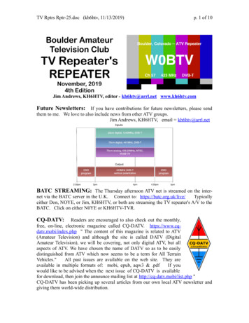
Figure A2.4.The LNB (Low Noise Block-converter) is an active device fruit of the greatevolution of RF circuit manufacturing and includes amplifiers, oscillators andfrequency converters in a small low cost package. The first section is made of adevice called polarisation shifter that receives one polarisation or the otherdepending on the supply voltage given to the LNB. This voltage is necessary tosupply the active devices inside the LNB.Signals broadcast from the satellites use two polarisations simultaneously. Thesecan be LINEAR VERTICAL/HORIZONTAL or CIRCULAR LEFT/RIGHT depending onthe type of transmitting antenna used in the satellite. The transponderfrequencies for each polarisation are carefully selected to avoid interference tothe other polarisation commonly referred to as the crossed polarisation. Ingeneral they are imbricate or in other words frequencies used in one polarisationare free in the crossed polarisation and viceversa.13 VDCVERTICALCIRCULAR RIGHT18 VDCHORIZONTALCIRCULAR LEFTModern universal LNB's use mostly linear polarisation and have also thecapability to select a different input frequency range depending on a controlsignal called 22 kHz switching tone which is overlapped with the supply voltage.SUPPLY VOLTAGEPOLARISATIONBAND13 VDCVERTICALLOW18 VDCHORIZONTALLOW13 VDC 22 kHzVERTICALHIGH18 VDC 22 kHzHORIZONTALHIGHIn other words our LNB will output a different set of satellite transpondersdepending on which supply voltage we use.May 2016
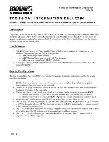
Figure A2.5. An example of LNB(Low Noise Block-converter)A2.1.3Coarse dish alignmentWe can use different techniques to find out where in the sky the satellite we wantis located. They can be anything from a pure guessing game to a sophisticatedprocedure.The satellites we are interested in are all positioned in a geostationary orbitabove the earth's equator. Each of them has a fix given position in that orbit,something like a street number, that we can know from various sources. Orbitalposition is an important datum so it is commonly part of the name as well.Websites like http://www.lyngsat.com/ or http://www.satcodx.com/ offer plentyof useful information about the satellites we are talking about.For example ASTRA 19E refers to ASTRA satellite which is positioned at 19degrees East in the orbit.Knowing where we are in terms of latitude and longitude is also easy. We canread that information from a map or even from our car's navigation system if wehave one.Figure A2.6.May 2016
With this information in hand we can calculate the elevation and azimuth weshould put on the dish to begin our coarse antenna alignment. There areformulas to do that but some websites are again quite useful. There are also freemobile applications, as Dish Aligner, which calculates the elevation and azimuthand also your current location determined by the GPS of the mobile phone. Thisone is especially interesting for you can select the satellite you want and thenposition yourself on a graphical ack3D.html/For example if we take ASTRA (19E position) and select a location somewhere inGermany: Latitude: 50 degrees North Longitude: 12 degrees EastThe required elevation and azimuth for the dish are: Azimuth: 170 degrees Elevation: 31 degreesElevation must be measured from the horizontal level (may be using aninclinometer) and azimuth from magnetic north (with a compass) there are someapplications for smartphones, as mentioned above, that include compass andinclinometer, although it should be noted that the measurements made bymobile phone may be affected by interferences from the antenna itself. It isnormally more practical to start with azimuth moving the dish horizontally andthen look for the elevation.Figure A2.7.May 2016
A2.1.4Knowing what satellite we are onAnd the HD RANGER 2 comes into action. Our dish is now more ore less"looking" in the direction where we presume our "bird" is parked. With theHD RANGER 2 connected to the output of the LNB we select satellite frequencyrange, antenna alignment mode, span of 200 MHz and set the power supplyvoltage to one of the possible values. We will take for example 13 VDC, whichwill take us to the VERTICAL polarisation and LOW band. We can use 80 dBµV forthe reference level for we can change that at pleasure depending on the amountof signal we get.Something will come up on the HD RANGER 2 screen. It will normally be aweak signal that may come from the desired satellite or from the neighbour onesfor the dish is not properly tuned up yet. Swing the dish slightly horizontally andvertically until a decent signal is shown on the screen.There we have a satellite but which one is it? Most probably the signals we arelooking at are digital transponders from the unknown satellite. TheHD RANGER 2 can be operated in frequency or channel modes.Tune any of those digital channels in frequency mode using the joystick and themarkers shown on the screen. The HD RANGER 2 will tell you what satelliteand/or orbital position you are on in a matter of seconds !If we are unlucky and this is not the satellite we want then we only need to movethe dish slightly to pick the signal from the next satellite and repeat the process.Figure A2. 8.May 2016
A2.1.5Fine tuning the dishOnce we know for certain that we are on ASTRA 19E it is time to make fineadjustments to the dish to optimise the alignment. There are two goals toachieve. On the one hand we want to receive the maximum amount of powerpossible and on the other hand we need to make sure we minimise theinterference from the crossed polarisation.In order to maximise the received signal power we need only to move the dish'sazimuth and elevation very carefully ensuring that the display of the spectrumanalyser show us the highest values possible.As you move the dish's position you will see the signal change on the spectrumanalyser. Cross-polarisation is adjusted by rotating the LNB on its axis. As you doso you will see on the HD RANGER 2 screen how the channels interfering fromthe opposite polarisation go up and down the objective being to leave the LNB insuch a position that those channels are as low as possible.A2.1.6Testing signal qualityThe HD RANGER 2 is the ideal instrument for quick and effective checks ofsignal quality not only because it shows all measurements in one single screenbut also because the meter doesn't require bothering configuration processes. Option 1: Frequency modeI can tune in frequency mode all channels coming up in the screen, all ofthem or the most representative ones only. We can move our cursor infrequency mode, in spectrum, through out the band. When we stop on achannel, the meter will acquire all the settings needed to measure thechannel without bothering us. Then pressing the measurement button andvoilà. Option 2: Channel modeI can select channel mode and a satellite channel table from the list. TheHD RANGER 2 has several of them preloaded but this can be changedusing software application.Once we select the desired table, ASTRA 19E in this case, we can browse thechannels at once. There are channel tables grouped by polarisation or bandor those with all channels in the satellite.May 2016
A2.1.7Look what we’ve gotThe HD RANGER 2 can also display the free to air programs available in thesatellite. That is very practical not so much for the picture itself but for amountof interesting data related to the transponders we can display as well. Thisincludes:Tuned video information. TYPE: FORMAT: PROFILE: PID:Encoding type and video transmission rate.Resolution (horizontal x vertical), aspect ratio andfrequency.Profile level.Video program identifier.Tuned service information. NETWORK: PROVIDER: NID: ONID: TSID: SID: MHP: LCN: Info:Television distribution network (Terrestrial). Orbitalposition (Satellite).Program provider name.Network identifier where the signal is distributed.Identifier of the original network where the signaloriginates.Transport stream identifier.Service Identifier.Interactive service.Logic Channel Number. It is the first logic numberassigned to the first channel in the receiver.Additional service information. FREE/SCRAMBLED: DTV/DS:Free/scrambled transmission.Standard type of transmission.Tuned audio information. TYPE:Type of audio encoding and transmission speed FORMAT:Service audio format. Bit depth; sampling frequency;sound reproduction. LANGUAGE:Broadcasting language. PID:ID of the audio program.At any time it is possible to display the SERVICE LIST pressing the F3 key andshow all the programs and services available within the tuned channel. Selectingone particular channel or service becomes very intuitive.May 2016
in the to-do-list if we want to install a satellite dish properly. Surely the list will require us to select the proper mount kit and dish size from the numerous options available in the market, pick a good location for the dish, free of obstacles to the south (in the north hemisphere) or to the north (in the south hemisphere), etc.