Transcription
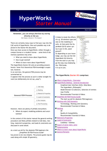
HyperWorksStarter ManualPage 1March 2011Remember, you can always find East by staringdirectly at the sun.Bart Simpson, character in "The Simpsons"There are certainly many ways to find your way into theCAE world of HyperWorks. One such possible way is depicted in the Starter-Kit document.Once you have access to HyperWorks—either through acampus license or a student license — some kind of elementary questions may arise:What you need to know about HyperWorksHow to get started?Where to learn more about HyperWorks?The HyperWorks Starter-Kit aims at providing answershereto. Some first theoretical FEM knowledge is expected, however.In an overview, the general FEM process may besummarised as:It appears that the process as such is rather straight forward (we deliberately do not say „easy―).However, there are plenty of pitfalls everywhere.Where do expect modeling problems and uncertainites?In the context of this starter manual the general workingprocedure and likely pitfalls related to CAD data, meshing, material & properties, and loads & constraints arediscussed in some detail.As a start-up aid for the absolute FEM beginners the„Simplified 3D FEM Process Guide―has proven to be very helpful. The process guide may beused along with simple 3D geometry.It helps to study the effectsof e.g. 3D element type andsize on the modeling results. At that point the HyperMesh GUI & solver syntax is put in the „background―.So depending on your knowledge, you may use the fullHyperMesh GUI directlyfrom the start or you maygo the easy way employingthe FEM Guide.It is up to you.The HyperWorks Starter Kit comprises:What is HyperWorks— OverwiewHyperWorks Desktop - General IntroductionGraphical User Interface (GUI), Help MenuThe HyperMesh „Philosophy―Model Browser & Collectors, Selection of entitiesUser ProfileRecommended Tutorials & VideosSimplified 3D FEM Process GuideThe start-up aid for absolute FEM beginnersWorking with CAD GeometryTerminology, Working with GeometryRecommended Tutorials & VideosMeshing2DQuality & CompatibilityRecommended Tutorials & VideosMaterial & PropertiesLoads & ConstraintsLoadstep / SubstepExport of solver deck, solvePostprocessingWhere to learn more about HyperWorksGeneral Remarks
HyperWorksStarter ManualPage 2What is HyperWorks—Overview (I)HyperWorks , The Platform for Innovation HyperWorks is an enterprise simulation solution for rapiddesign exploration and decision-making. As one of themost comprehensive CAE solutions in the industry, HyperWorks provides a tightly integrated suite of best-inclass tools for modeling, analysis, optimization, visualization, reporting, and performance data management.Firmly committed to an open-systems philosophy, HyperWorks continues to lead the industry with the broadestinteroperability to commercial CAD and CAE solutions.HyperWorks Modeling & VisualisationHyperWorks Desktop Integrated user environment formodeling and visualizationNote: The HyperWorks 11.0 Student Version and theStarter-Kit are based on the HyperWorks Desktop Solution. Nevertheless, the Starter-Kit is also suited for usersemploying the „stand-alone― HyperMesh and HyperViewversions. The products referenced (and employed) in theStarterKit are marked bold & italic!HyperMesh Universal finiteelement pre- and postprocessor.HyperMesh is a highperformance finite elementpre- and post-processor formajor finite element solvers, which allows engineersto analyze design conditionsin a highly interactive and visual environment. HyperMesh’s user-interface is easy to learn and supports the direct use of CAD geometry and existingfinite element models, providing robust interoperability and efficiency. Advanced automation toolswithin HyperMesh allow users to optimize meshesfrom a set of quality criteria, change existing meshesthrough morphing, and generate mid-surfaces frommodels of varying thicknessMarch 2011MotionView Multi-body dynamics pre- and postprocessorHyperView High performance finite element and mechanical systems postprocessor, engineering plotter, and data analysis toolHyperView is a complete post-processing and visualizationenvironment for finite element analysis (FEA), multibody system simulation, video, and engineering data. Amazingly fast 3-D graphics and unparalleled functionality set a new standard for the speed and integration of CAE resultspost-processing. HyperView enables you to visualizedata interactively as well as capture and standardize your post-processing activities using process automation features. HyperView also saves 3-D animation results in Altair's compact H3D format so youcan visualize and share CAE results within a 3-Dweb environment using HyperView Player.HyperGraph Engineering plotter and data analysis toolScriptView HyperWorks IDE (Integrated DevelopmentEnvironment) for developing and debugging TCL andHyperMath Language (HML) scriptsTemplex General purpose text and numeric processorBack to page 1
HyperWorksStarter ManualPage 3What is HyperWorks—Overview (II)HyperWorks , The Platform for Innovation HyperWorks SolversRADIOSS Finite element solverfor linear and non-linearproblemsRADIOSS is a state-of-the-artfinite element solver unitingimplicit and explicit integration schemes for the solutionof a wide variety of engineering problems, from linear statics and linear dynamics to complex nonlineartransient dynamics and mechanical systems. Thisrobust, multidisciplinary solver enables designers tomaximize performance related to durability, NVH,crash, safety, manufacturability, and fluid-structureinteraction, in order to bring innovative products tomarket faster.AcuSolve General, all-purpose finite element computational fluid dynamics (CFD) solverMotionSolve Multi-body dynamics solverOptiStruct Design and optimization software using finiteelements and multi-body dynamicsHyperWorks EnterpriseCollaboration Tools A solution that organizes, manages,and stores CAE and test data throughout the simulation life cycleProcess Manager Process automation tool for HyperWorksand third party software; Processes can be createdwith the help of Process Studio.HyperMath SolutionsHyperMath Mathematical scripting language for numerical computationHyperStudy Integrated optimization, DOE, and robustdesign engineCAE Result PlayerHyperView Player Plug-in and stand-alone utility to shareand visualize 3-D CAE models and resultsMarch 2011Manufacturing SolutionsManufacturing Solutions A unified environment for manufacturing process simulation, analysis, and designoptimizationHyperForm A unique finite element basedsheet metal formingsimulation softwaresolutionHyperXtrude An finiteelement solver anduser environment that enables engineers to analyzematerial flow and heat transfer problems in extrusion and rolling applicationsHyperMold Provides a highly efficient and customizedenvironment for setting up models for injectionmolding simulation with Moldflow and Moldex3DHyperWeld Provides an efficient interface for settingup models and analyzing friction stir welding withthe HyperXtrude SolverForging Provides a highly efficient and customized environment for setting up models for complex threedimensional forging simulation with DEFOM3DResults Mapper Process Manager-based tool that provides a framework to initialize a structural modelwith results from a forming simulationEngineering SolutionsEngineering Solutions A unified environment tailoredspecifically for certain engineering applicationsHyperCrash Specialized modeling environment for automotive crash and safety analysissolidThinkingsolidThinking Comprehensive NURBSbased 3D modelingand rendering environment for industrial designsolidThinking InspiredInnovative morphogenesis form generation technologyBack to page 1
HyperWorksStarter ManualPage 4General Remarks (I)The HyperWorks Desktop Graphical User InterfaceMarch 2011Under Help-HyperWorks Desktop you will find answersrelated to „panels/functions― and working techniques.Tip: Just press „h― onyour keyboard whileyour inisde a panel ofHyperMesh and youwill be directly guidedto the corresponinghelp entry!In the Desktop environment you may switch betweendifferent applications (clients) such as HyperMesh,HyperView, and HyperGraph etc. In addition, the screenmay be divided according to your needs, allowing you toplace, for instance, a HyperMesh window next to a HyperView window.Whenever you wonder about FEM solver related issuessuch as syntax, material definitions etc. you need togo to „Other Applications―The HyperMesh „Philosophy“Help document: HyperMesh User's Guide The HyperMeshEnvironmentTip: Start learning HyperMesh by using the Menu BarThe topics/titles in the Menu Bar (e.g. Geometry,Mesh, Materials, Properties, Bc‘s etc.) and the pulldown menus are organized in such a way that you canbuildThe HyperWorks Help DocumentationThe HyperWorks Help documentation is part of the HyperWorks installation. The help menu may be accessedin different ways.For instance, just activate „Help― in the Menu Bar.„sentences―. For instance, building a surface:
HyperWorksStarter ManualPage 5General Remarks (II)So the „sentence― would read:Geometry—Create—Surfaces-.After that a panel will be displayed offering differentmethods on how to create the surface.March 2011All entities of the FEM model such as elements, geometry, materials, properties, loads, etc. are stored incorresponding collectors:How to read panels (e.g. create surface—ruled)?Yellow HyperMesh expects your input here. The bluecolored frame indicates which field expects your input (you can jump between yellow panels by mouseclicking or by activating the tab-buton)Green Action. In this case the surface would be buildwith respect to the specified lines.Red Close panel. No further action.Tip: Always watch the „Status Bar“ (left lower panel)for information!The information provided there is instrumental for yourwork (at least until you have a sound understanding onhow HyperMesh works).It is exacty this „spot― which tells you what is happening, what is missing, what was created etc.!!Model BrowserIn HyperMesh there are many browsers. The most important one to get started with is the „Model Browser―Help document: HyperMesh User's Guide Browsers Model BrowserElements & CAD: component collector (comps)Material: material collector (mats)Properties (e.g. thickness of shell elements): propertycollector (props)Loads: load collector (loadcol)Collectors are best created within the model browser.Note: the collector writtenin bold letters is currentlyactive. The active collectoris the storage place fornewly created entities belongign to this brand ofcollector.Collectors can bemade active simply with:„Make current“.In this example the activecomponent collector is named „rigid― which impliesthat newly created elements will be stored under„rigid― (regardless whetherit is meaningful or not).Back to page 1
HyperWorksStarter ManualPage 6General Remarks (III)March 2011The model browser is a kind of „list of contents― providing information about the loaded FEM model.In this depicted example the mesh of the model is storedin a component named„mesh―, the componentowns a number (ID) and acolor. The lD is being usedby the FEM solver, thecolor is used for displaying elements.At the same time the model browser controlswhich FEM entities arebeing displayed.Elements of the corresponding component may bedisplayed or non-displayed by activating –deactivating the iconGeometry of the corresponding component may bedisplayed or non-displayed by activating–deactivatingthe icon.Note: All entities MUST (and will be) be placed in a corresponding collector.If you miss to create the respective collector before theentity is created, HyperMesh allocates the corresponding collector typeautomatically. This collector is named „auto―.Don‘t worry— you can change it‘s name, color etc. atany time. It is just rightmouse click in the modelbrowser.You can also move entitiesfrom the same type of collector (e.g. componentcoll.) to another – at anytime.Selection of entities(entities elements, geometry etc.)Help document: HyperMesh User's Guide The HyperMesh Environment The HyperMesh User Interface Input ControlsIn order to select, for instance surfaces, it is imperative that the activated (opened) panel requests this kindof information.Example: The panel Geometry-Create-Lines-from nodesdoes not say anything about surfaces. Hence, there isno way to select surfaces in this panel.Incontrast, in the Geometry-Create-Lines-from surfedges panel you are „asked― to provide the informationfrom whichsurface edges linesshould be derived. Hence, you can (actuallly have to)select surfaces.The respective surfaces can be selecteddirectly via left mouse botton (deselection right mouse button).Of course, other selection options do exist.Read more:Help document: HyperMesh User's Guide The HyperMesh Environment The HyperMesh User Interface Input ControlsBack to page 1
HyperWorksStarter ManualPage 7General Remarks (IV)March 2011Panels: General LayoutPanels often have sub-panelsAccessed by radio buttons on the left side of thepanelPanels generally work from left to rightExample: Project / to plane sub-panMouse ButtonsLeft mouse button CTRL & drag for rotate CTRL & click on entity to change center ofrotation CTRL & click in graphics area, off entities toreset center to middle of screenMiddle mouse button CTRL & drag for zoom CTRL & click for fitHyperMesh allows you to build FE models for other popular solvers as well. For instance, you can export yourmodel in the format of Abaqus, Ansys, LS-Dyna, Marcetc.Recommended Tutorials:Help Document: HyperMesh Tutorials Basics Getting Started with HyperMesh - HM-1000Opening and Saving Files - HM-1010Right mouse button CTRL & drag for panWorking with Panels - HM-1020Organizing a Model - HM-1030Controlling the Display - HM-1040User ProfileMost likely your work will not end with meshing.Whenever FEM solver specific information needs to beapplied to the model, it is again imperative to „inform―HyperMesh about the FEM solver to be used.This is managed through the User Profile.Note: In the HyperWorks Student Version Radioss (bulk),OptiStruct and the „Simplified FEM Process Guide― areavailable, only .Recommended Videos:(to view the free videos, you need to register at theHyperWorks Client Center using your university E-Mailaddress)Interactive Tutorials (no HyperWorks installaltion required)HM-1010 Opening and Saving ModelsHM-1020 Working with PanelsHM-1030 Organizing a ModelBack to page 1
HyperWorksStarter ManualPage 8The 3D Simplified FEM Process GuideThe 3D Simplified FEM Process GuideIdeally, the FEM novice should explore the effects of, forinstance element type and mesh size on the modelingresult first. Simple models, with an given analytical solution are quite helpful in this regard.In this first phase the usage of the FEM system should beas easy as possible. Due to the rather steep learning curve FEM beginners evolve into experts rather fast askingfor more sophisticated technologies e.g. hexahedralmeshing, morphing, midsurface generation, etc. Insteadof switching over to a new expert system with a new GUIand philosophy, it is far more efficient to stick to theknown FEM system with expanded functionalities.The 3D Simplified FEM Process Guide is the „bridge―linking the two different requirements!March 20112. Start volume meshing (tetra– or hexahedral mesh, 1stor 2nd order).3. Create the material (linear elastic). It then will beautomatically assigned to the volume elements.4. Finally, specify the loads and constraints.Note: Component-, property-, material-, load collectors as well as the loadstep are automatically createdAt „Solve Analysis― you may also view the FEM inputdeck (ASCII Syntax) as well as the solver log file.The solver log file cotains information about modelsize, estimated memory and CPU and lists (comments)any warnings and errors. Take some time and view bothfiles.The process guide is available as a User Profile(HyperWorks 11.0 Student Version) or as an externalroutine which needs to be manually loaded into Hyper-Mesh (no installation required). You may download theprocess guide and a short explanation from within theAcademic Blog.Note: The 3D Simplified FEM Process Guide works forsimple solid geometries only, allowing for either tetra–or hexahedral meshing.Theprocess guides you through all the instances of modelcreation—analysis—and postprocessing.1. The project parameters are defined, i.e. title of theproject (later used as the model file name), date, unitsetc. The model as such is either loaded (HyperMesh fileor CAD data) or manualy created through nodes, lines,surfaces and solids.Back to page 1
HyperWorksStarter ManualPage 9Geometry (I)GeometryTypically your CAE projects starts with the import ofgiven CAD data e.g. CATIA, STEP, UG, IGES, SolidWorksetc. (of course, you may create your CAD model in HyperMesh as well).Many times the troubles start now as the imported geometry is not reasonably meshable (btw, this one of themany reasons why HyperMesh is used in so many placesi.e. HyperMesh is a commercial expert system with superior tools to overcome meshing troubles).Some problems related to geometry:Surfaces are not stiched together (i.e. there is agap between surfaces)March 2011What you need to know / remember:Geeen edges - 2 surfaces are stiched togehter; the FEmesh will be linked (compatible), its nodes will lineup with the green edge.Red edges - indicates free surface edges.Attention: red edges inside the geometry tell youthat the surfaces are not stiched together ( gap);the FE mesh will NOT be linked (not compatible).Yellow edges — minimum of 3 edges are stich togehter;the FE mesh will be compatible.Blue edges — Suppressed green edge. Surfaces are„melted― togehter. In other words, the mesher doesnot feel this edge, elements are placed across it.Very small surfaces are squeezed between regularsurfacesSurface edges do not line up properly forming„jumps― (see figure below. Left: CAD with„jumps; Middle: mesh with irregual shaped elements; Right: improved CAD with regular mesh)The geometry is a thin-walled volume structure simplification needed: mid-surface modelSurfaces intersect (t-connection) but don‘t „feel―each otherGeometry is much too detailed (e.g. tiny filletswhich are not needed for the analysis) and manymore .All these issues typically result in apoor quality mesh!How to visualise the edge „colors―?Display is controlledin the „Tool Bar― byactivating for instance „By 2D Topo― (surfaces turninto grey, edges arecolored respetively)or „Mixed― (surfacesare displayed in theiroriginal color (reminder: surfce color is controlled inthe model browser), edges are colored respectively.Panels to be used for:Toggle surfaces (combining,stitching )Trimming surfaces (splitting)Suppressing combined edgesTool Bar-Geometry-Quick Edit opensup a very comprehensive panelwhich allows you (among many otheroptions) to execute the above listedtasks.Back to page 1
HyperWorksStarter ManualPage 10Geometry (II)How to create geometry (e.g. surfaces)?Just follow the standard recommendationmade earlier — makeuse of the Menu Barand try to build a sentence:Geometry-CreateSurfaces– and thenchoose the way thesurface should becreated ( quite self-exemplanatory)In fact, the same rule (procedure) applies to otheritems/entities as wellMarch 2011If you are targeting at hexahedral meshes (brick elements) then better use „Mapple―. This mode displaysimportant hexameshing information such as, can thepart be automatically hexa-meshed etc.The before mentioned panels describe just a very minor fraction of HyperMesh‘s geometry cleanup funtionalities.Once you feel more comfortable with the process, youwill automatically explore and learn more about othertechniques.Recommended Tutorials:Help Document: HyperMesh HyperMesh Tutorials GeometryImporting and Repairing CAD - HM-2000Note & reminder: The newly created geometry will beplaced /stored in thecurrently active component collector. Checkthe model browser.Refining Topology to Achieve a Quality Mesh -If you are working on asolid geometry, the above listed rules alsoapply.Panel - HM-2070To display informationabout thesolid geometrytopologyHM-2030Creating and Editing Line Data - HM-2040Creating and Editing Solid Geometry - HM-2060Geometry and Mesh Editing Using the Quick EditRecommended Videos:(to view the free videos, you need to register at theHyperWorks Client Center using your university E-Mailaddress)Product Video (no HyperWorks installation required)Edit Geometry DemoInteractive Tutorial (no HyperWorks installation required)HM-2000 Importing and Repairing CAD Models(„connectivity―) activate „By 3D Topo―.Back to page 1
HyperWorksStarter ManualPage 11Meshing (I)MeshingOnce geometry cleanup (e.g. surfaces ares stitched together — nounwantedred edgesinside thegeometry) iscompletedmeshing isnext.Some rules of thumb first:The mesh should lookra the r s m oo th a ndregular (keep in mindthat the analysis isbased on your mesh &mesh quality.Use the simplest element type suited forthe problem.March 2011What you need to know:Element size the element size in the model may deviate from the specified size considerably (it depends onthe size of the surface)Mesh type mixed; default (is a combination of manyquad-shaped elements and some tria elements). Leadsto rather smooth meshes.Elems to surf comp vs. Elems to current comp specifies the „storage― place of the elements (please seeGeneral remearks II & III).Start meshing, explore the meaning of the other settings latter!What may happen is that the mesh looks a bit wired Some surfaces apparently have cause troubles. Notreally. It is a matter of your visual settings. In thisexample the geometry is still shaded, overprinting themesh in some spots. Putting the geometry in wireframeand shading the elementsimproves the mesh visibility.Start with a coarsemesh and understand the modeling results; thenuse a finer mesh if neededTry to limit mesh related uncertainites to a minimum if possible—make it simple it will get morecomplicated automatically2D MeshingMenu Bar—Mesh—Create—2DAutomeshNote: Remember the sentencestructureNote: In case you don‘t see any mesh, check the modelbrowser and the status of the corresponding collector(is theelem iconactivated?)The 2D meshing panel is thenopenedBack to page 1
HyperWorksStarter ManualPage 12Meshing (II)How to check element quality?Activate the corresponding icon will open upthe check elements panelMarch 2011Advanced:Most likely, the following section exceeds the intentions of this Starter Kit as we‘re going into some details:How to isolate the failed elements from the rest?Just follow this process:Perform element check (e.g. length)Activate „save failed― ( failed elements arestored in the User Mark)Insert your values and then Green action.In the Status Bar you will find a summary about the number of checked elements, failed elements etc.Some typical values (depended on the simulation; not aMUST)Warpage 20Aspect 5Skew Min angle Quads 40Max angle Quads 140Min angle Tria 30Max angle Tria 15Length Jacobian 0.5Taper 0.5 / ?What you need to know:The element check is performed with respect to theelements displayed, and NOT with respect to the entiredatabase of the model (which may contain more elements).Read more:Help document: HyperMesh Meshing Checking & Editing MeshTurn all elements off from the display (best byusing the Model Brow-ser)Activate the Find iconto find elements stored in the UserMark.Elements in the User Marsk can be accessed byclicking the yellow „elems― panel (whichopens the extend selection window), select„retrieve“This action will display the failed elementsonly.In order to better understandwhere are the failed elements / and why they failedadd adjacent elements to thedisplay by clicking on the iconBack to page 1
HyperWorksStarter ManualPage 13Meshing (III)Whenever you encounter bad quality elements it is important (actually helpful) to understand its causes.Most of the time, bad quality elements can be found atsurface edges due to „misaligned― surface edges.March 2011Geom-wireframeElems-shadedMesh compatibilityHow to check for elements not properly merged(linked) together?Meshing this area leads to (unwanted) tapered elements.Improving the surface connectivity, for instance bysurpressing a green (shared) edge (toggle) or by replacing the geometry points to the same location, or bysplitting (trimming) the surfaces produces a highly improved mesh.To resolve this issue, you may try the functionality:Geometry-Quick Edit-toggle edge; or replace point orsimply split (trim) surface-nodeWhat you need to remember:After meshing iscompleted your results may look„strange―:You may see onlysome elements;others seem to disappear etc.Make sure that the geometry visualisation is set to wireframe and the element display is set to be shaded.To search fornodes being notequivalenced(merged) useMesh-CheckNodesEquivalenceIf free elementedges are found(i.e. their nodesnot being merged with othernodes), 1D Plotelements areautomaticallycreated and stored in the component collector named edges. Just turn off all other component collectors(through the Model Browser) and you will see the„problematic― areas (connectivities).Still, in big models these problematic spots may behard to see. Therefore, add (attach) the 2D elementsadjacent to the 1D Plot elements i.e. these are theelements which are not properly merged. Hereto, just activate the icon:Unmask AdjacentThis will eventually create „Islands oftroubles―which help you to locateand understand its causes.Back to page 1
HyperWorksStarter ManualPage 14Meshing (IV)March 2011Recommended Tutorials:Help Document: HyperMesh Tutorials Meshing 2-DElements AutoMeshing - HM-3100Checking and Editing Mesh - HM-3300Recommended Videos(to view the free videos, you need to register at the HyperWorks Client Center using your university E-Mailaddress)Product Videos (10-15 minute; no HyperWorks installation required)Mesh Creation and Editing DemonstrationEditing Mesh DemonstrationToplogy Revision Using Quick Edit and AutomaticRemeshingInteractive Tutorials (no HyperWorks installation required)HM-2030 Refining Topology to Achieve a QualityMeshHM-3100 AutoMeshingBack to page 1
HyperWorksStarter ManualPage 15MaterialMarch 2011MaterialIf not already previouslyspecified it is now imperative to define the User Profile(FEM Program to be used for the analysis). Here we usethe User Profile OptiStruct.Reminder: In the HyperWorks Student Version Radioss(bulk), OptiStruct and the„Simplified FEM ProcessGuide― are available,only .Defining Material Data:There are multiple ways to create FE entitites such asurfaces, elements, materials, loads etc.1. One simpleway is a rightmouse buttonclick in theModel Browser(CreateMaterial).2. This opensup a windowasking you forthe materialtype e.g. Isoptropic.3. Assign a name to it e.g. steel (note: there is no material database behind steel, you‘ll need to specify thedata in the next step yourself).4. Specify aCard Image (Card images are defined within a solverinterface template and allow for creation, editing, anddeletion of a solver card within a HyperMesh model (insimpler and less acurate words — the Card Image defines the FEM solver syntax)MAT 1 defines the material properties for linear, temperature-independent, isotropic materials.Typically you need to now values for Young’s Modulus(E); Poisson’s Ratio (nu); Mass Density (Rho). Just clickon the corresponding „label― which then will open up afield allowing you to enter the corresponding value.General Information about MAT1:Help Document: Reference Guide Bulk Data Format Input Data Bulk Data Section: MAT1Recommended Reading:Help Document: Reference Guide Bulk Data Format Input Data Material Property Check:Material Property Checks for MAT1Back to page 1
HyperWorksStarter ManualPage 16Material & Property (I)March 2011Note: Pay attention to the unit system—be consistentthroughout your model e.g. don‘t mix mm and m or kilogram and tons in the model In fact, chosing the corect units will make your life easier. For instance, if you use Force in N, Young‘s Modulus in N/mm2, Mass in tons, Density tons/mm3 etc. thecalulated stresses will be displayed in MPa directly.Most popular units are:PropertyAs with the material definition, make use of the ModelBrowser – Right Mouse Button Click:In the following we assume that the model consists of2D elements.1. We need to set the Type to 2D2. Assign a name to the property e.g. prop 2D3. Specify a Card Image ( FEM solver syntax):PSHELLGeneral Information about PSHELLHelp Document: Reference Guide Bulk Data Format Input Data Bulk Data Section: PSHELL4. Before creating the Property Collector, select theregister Material, activateAssign material, and selectthe previouslycreated material (if youwish to viewthe material(its vlaues)just click onEdit).Back to page 1
HyperWorksStarter ManualPage 17Property (II)4. Make sure that the check box:„Card edit property upon creation― is activated.Only then you‘ll see „inside― the property collector :March 2011To visually check the property (and hence material)assigned to the elements change the visual attributesof the elements:You will note that the elements will be displayed in thecolor of the material– and property collector, respectivly.As we are dealing with 2D elements all you need todo is to specifiy their assigned thickness T.Thus, the Property Collector comprises informationabout both, the (element) thickness and the material tobe used.Note: If you need e.g. 4 different T values you need tocreate 4 different property collectors.Note: Elements without assigned property or materialwill be shown in grey color.Tip: Never use grey color for property and materialcollector as it will hinder the visual check.We are almost through!5. The property collector must be assigned to theelements. Inthe ModelBrowser RightMouse ButtonClick on theproperty collecto
In the context of this starter manual the general working procedure and likely pitfalls related to CAD data, mes-hing, material & properties, and loads & constraints are discussed in some detail. As a start-up aid for the absolute FEM beginners the „Simplified 3D FEM Process Guide― has proven to be very helpful. The process guide may be
