Transcription
Marius MüllerTutorial:Composite optimization of a skateboard usingAltair HyperMesh and Altair OptiStruct 2019 Marius MüllerGraz, March 2020
I. PrefaceAt the beginning it’s important to say that the original tutorial “Composite optimization of askateboard with OptiStruct” from Altair University was written by Nicolas Torgau. Afterwardsthe tutorial was edited by Kevin Illgen and Mathias Kölbel (former members of WHZ RacingTeam Zwickau). The previous tutorial was carried out with an older version of AltairHyperMesh and Altair OptiStruct . For the following tutorial HyperMesh 2019 andOptiStruct 2019 were used.Compared to the original tutorial a few changes in the text were made, new texts and pictureswere added.For this tutorial a basic understanding of manufacturing of composites is required.II. IntroductionThis tutorial should help students and young engineers to get an easy access and to gain firstexperiences in composite modelling, analysis and optimization. Chapter 1 covers basic aspectsof composites, continuing chapter 2 covering the modelling process of composites using AltairHyperMesh . Geometry preparation, FE (Finite element)-model generation and post-processingare carried out in chapter 3. Chapter 4 covers the optimization process and the tutorial ends witha summary table in chapter 5.Page 1
Content1. Composite theory. 31.1. Composite materials . 31.2. Fibres . 31.3. Matrix of carbon fibre reinforced plastics . 31.4. Prepregs . 41.5. Sandwich constructions . 72. Modelling of composites with Altair HyperMesh . 82.1. Modelling of composites . 83. FE-model generation, analysis and post-processing of skateboard . 123.1. Import geometry . 123.2. Meshing of the geometry . 123.3. Checking element normal . 163.4. Checking element/material orientation. 183.5. Material generation. 223.6. Ply generation . 223.7. Laminate generation . 253.8. Laminate generation . 253.9. Loads . 283.10. Rigid elements and boundary conditions (BCs) . 303.11. Run the Analysis . 333.12. Post processing . 344. Optimization of the skateboard . 404.1. Modelling of composites . 404.2. Free-size optimization . 404.3. Size optimization . 514.4. Shuffle optimization . 565. Summary table . 60Page 2
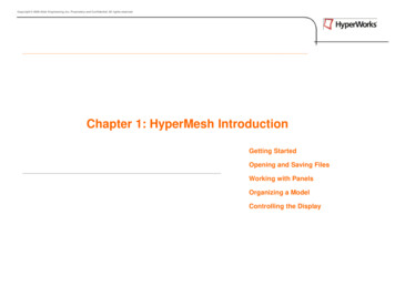
1. Composite theory1.1. Composite materialsA composite material is a material that is formed by combining two or more materials on amacroscopic scale. [1]1.1.1. Particulate compositesParticulate composites are materials that are manufactured by spreading pieces of chopped fibrematerial onto a film of matrix material. [1]A schematic sketch of a particulate composite is shown in Figure 1.1.Figure 1.1: Schematic sketch of a particulate composite ply material [1]1.1.2. Laminated compositesLaminated composite materials are materials that are made up of any number of layeredmaterials, of the same or different orientation, bonded together with a matrix material. The layersof a laminated composite are usually called plies. Plies can be made from a wide range ofmaterials, including adhesive plies, metallic-foil plies, fibre-matrix plies of various fibre andmatrix material combinations, and core plies of various core materials. [1]1.1.2.1. Fibre-matrix laminated compositesFibre-matrix laminated composite materials are materials made up of any number of fibre-matrixplies, of the same or different fibre orientation, layered and bonded together with a matrixmaterial. [1]Fibre-matrix ply materials can be classified into unidirectional plies and weave plies:1.2. FibresIn order to be designated as lightweight construction materials, fibres must have high stiffnessand strengths as well as low densities. All the requirements are fulfilled by elements of the firsttwo rows in the periodic system: Boron, Carbon and Silicon. These elements have theoreticallyhigh atomic binding energies. The attempt is made to achieve the resultant high stiffness andstrengths by manufacturing fibres. [2]1.3. Matrix of carbon fibre reinforced plasticsThe matrix has to support the fibres and bond them together. It transfers any applied loads to thefibres and keeps the fibres in the chosen position and orientation. It also makes a maincontribution to the service temperature of a component. Furthermore, the matrix determinesenvironmental resistance and maximum service temperature of the ply. [3]Page 3
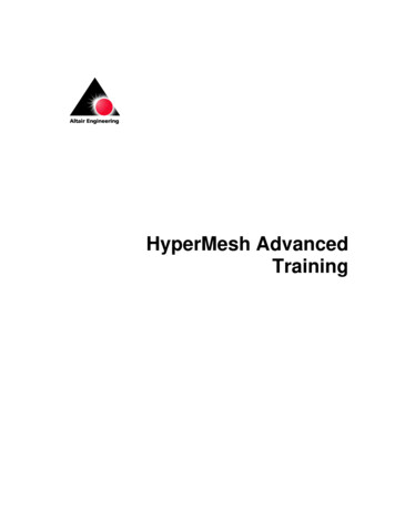
1.4. PrepregsPrepregs are fibre-reinforced resins that cure under heat and pressure to form exceptionally strongyet lightweight components. Prepregs consist of a combination of a matrix and fibrereinforcement. The position of prepreg technology in terms of performance and productionvolumes is compared in Figure 1.2 with other fabrication processes. [3]Figure 1.2: Performance and production volume of different fabrication processes [3]1.4.1. Types of reinforcementsThere are many reinforcement forms and each type offers different advantages. The two maintypes are listed below:1.4.1.1. Unidirectional reinforcementsUnidirectional ply materials are built up of straight fibres embedded in a matrix material. TypicalUD plies have fibre volumes which range from 45 to 70 percent. [1]Unidirectional reinforcements are used for components which are requiring predominant strengthand stiffness in one direction. Pressure vessels, drive shafts and tubes are examples of parts whichare produced using UD reinforcements [3]. Figure 1.3 shows a schematic of a UD ply material.Figure 1.3: Unidirectional ply material [1]Page 4
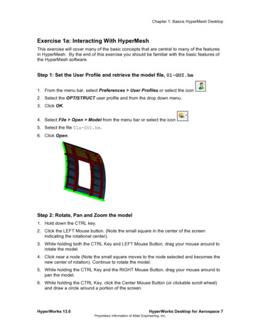
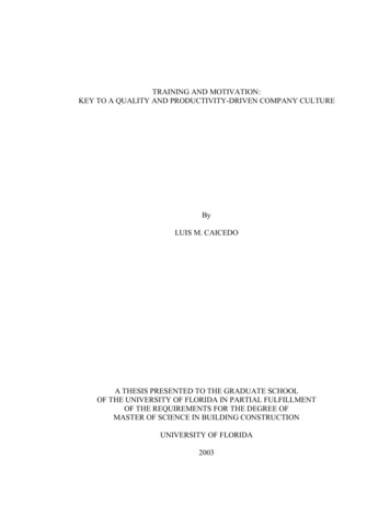
1.4.1.2. Weave pliesFabrics consist of at least two threads which are woven together - the warp and the weft. Weaveplies have reduced longitudinal stiffness compared to their equivalent UD ply product forms. Thereduced stiffness is due to the undulation of the fibres. The weave style can be varied according tocrimp and drapability. Low crimp gives better mechanical performance because straighter fibrescarry greater loads. A drapable fabric is easier to lay up over complex geometries. A mixture ofdifferent fibre and matrix material combinations is possible. [1] [3]The most important weave styles are shown in Figure 1.4.Satin weave(4, 5, 8, 11)Plain weaveLow drapeability / high crimpGood drapeability / low crimpTwill weave(2/1, 3/1, 2/2)Average drapeability / average crimpFigure 1.4: Three main weave styles of fabrics (recreated after [3])1.4.2. Prepreg processing techniquesThe most common prepreg processing techniques are the vacuum bag oven process, the autoclaveprocess, the match moulding process, the tube rolling process and the pressure bag process. Theprocessing method is determined by the quality, cost and type of component being manufactured.[3]1.4.2.1.Vacuum bag oven processA flexible bag, the vacuum bag, is placed over the composite lay-up and is subsequently sealed(see Figure 1.5a). The remaining air in the bag is removed by a vacuum pump. The removal ofair forces the bag down onto the lay-up with a pressure of up to 1 atmosphere (Figure 1.5b andFigure 1.5d). The complete assembly, with vacuum still applied, is placed inside an oven or aheated mould with good air circulation. The course of the temperature can be seen in Figure 1.5c.Vacuum bag processing is used to manufacture components of varying thickness and largesandwich structures. Examples are parts used in aerospace engineering, in the marine industry, forrailway interiors, wind energy and automotive purposes. [3]Page 5
a)c)b)d)Figure 1.5: Vacuum bag processing [3]a) Assembly b) Atmospheric pressure is acting c) Cure temperature d) Vacuum trend1.4.2.2.Autoclave processingThe autoclave processing is used to produce superior quality structural components containinghigh fibre volume and low void contents. For this process a vacuum bag is needed. The autoclaveis a pressure vessel which controls the application of the heat up rate and the cure temperature(Figure 1.6a), the pressure (Figure 1.6b) and the vacuum (Figure 1.6c), The manufacturabilityof high standard honeycomb sandwich structures is possible as well, typically at lower pressures.Long cure cycles are required because the large autoclave mass takes a long time to heat up andcool down and a temperature distribution on the tooling and composite components is required.[3]b)a)c)Figure 1.6: Autoclave process [3]a) Cure temperature and heat up rate b) Pressure trend c) Vacuum trendPage 6
1.5. Sandwich constructionsHoneycomb sandwich construction is one of the most valued structural engineering innovationsdeveloped by the composites industry [4]. Used extensively in aerospace and other industries [4],the honeycomb sandwich provides the following key benefits over conventional materials: [4] [5] Very low weight and durabilityHigh stiffness compared to its own weightHigh mechanical strength at low densitiesProduction cost savingAbsorption capacity relating to deformation energy (crash) and vibrations (structure-bornesound)The facing skins of a sandwich panel can be compared to the flanges of an I-beam, as they carrythe bending stresses to which the beam is subjected, with one skin in compression and the otherone in tension (Figure 1.7). The core resists the shear-load, increases the second moment of areaand so the stiffness of the structure by holding the facing skin apart (Figure 1.8). The core-to-skinadhesive rigidly joins the sandwich components and allows them to act as one unit with a hightorsional and bending rigidity. [4]Figure 1.7: Construction of a sandwich panel compared to anI beam [4]Figure 1.8: Relative stiffness and weight of sandwichpanels compared to solid panels [4]1.5.1. MaterialsThe composite structure provides great versatility as a wide range of core and facing materialcombinations can be selected. [4]1.5.1.1. Skin materialsTypical skin materials are epoxy carbon, epoxy glass and epoxy aramid. [4]1.5.1.2. Core materialsCore materials are available in a wide range of materials including foam through to honeycombs.Honeycomb materials are made of aluminium, aramid, Korex, Kevlar, fibreglass and carbon [4].Some characteristics of aramid honeycombs are: [4] Very low weightHigh stiffnessDurabilityProduction cost savingsPage 7
2. Modelling of composites with Altair HyperMesh 2.1. Modelling of compositesModelling laminated composites for FEA requires more information than isotropic parts: Part geometryPly geometryMaterial dataMesh dataMaterial alignment informationLayup sequenceZ-offset informationDrape informationIn general composites can be modelled by using single layer shells, multi-layer shells and/orsolids. In case of using solids, each ply has to be modelled with at least one layer of solidelements. This requires a huge number of solid elements. Using this method it should be kept inmind that the aspect ratio should not be greater than five to achieve a good element quality. InAltair OptistructTM solid elements are assigned with the property card PSOLID. [12]Building a laminate from shell elements requires a creation of property cards to define the ply an
09.12.2018 · HyperMesh and Altair OptiStruct . For the following tutorial HyperMesh 2019 and OptiStruct 2019 were used. Compared to the original tutorial a few changes in the text were made, new texts and pictures were added. For this tutorial a basic understanding of manufacturing of composites is required. II. Introduction