Transcription
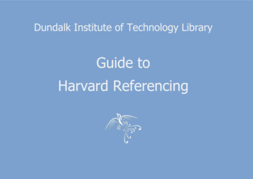
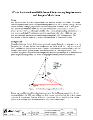
PV and Inverter‐based DER Ground Referencing Requirementsand Sample CalculationsScopeThis document lists technical requirements, and provides sample calculations, for groundreferencing of inverter based Distributed Energy Resources (DER) on Xcel Energy’s 4‐wiresystem medium‐voltage (MV) electric distribution system. DER units with AC nameplatecapacities from 100kW to 10MW are covered in the scope. This document assumes aproper ground reference is being created by either a separate grounding transformer or awye‐grounded:delta (MV:LV) interconnection transformer. Inverters which have aninternal grounded‐wye isolation transformer are not covered in this document. Theinformation in this document is to be applied at the Point of Common Coupling.BackgroundGround referencing electric distribution systems is standard practice in large part to avoiddamaging overvoltages, for line‐to‐ground connected loads, which can result from groundfault conditions on ungrounded systems. Figure A below shows the range of expected linevoltages for different system ground referencing methods. Line surge arrestors andcustomer equipment connected phase‐to‐ground are usually not designed to withstand thephase‐to‐phase voltages that can occur during ungrounded system fault conditions.Figure A – Neutral shift during ground fault conditionsDuring a ground fault condition, in situations where the Xcel Energy’s protective deviceopens and before the DER trips off‐line, the distribution system has lost the system groundreference. It is important that any DER source energizing this portion of the distributionsystem provides a ground reference in order to prevent overvoltages.By:Date11‐18‐15Apv’d:PLDPrev: N/AVer: 1.4PV Ground Referencing EDEDOC#:Requirements andSample CalculationsPage:SPAE‐DG‐21 of 8
Std IEEE 1547‐2003 states that “the grounding scheme of the DR interconnection shall notcause overvoltages that exceed the rating of the equipment connected to the Area EPS”. Thebelow requirements for inverter ground referencing are adopted from IEEE P1547.8/D8‐2014 which is the draft document titled Draft Recommended Practice for EstablishingMethods and Procedures that Provide Supplemental Support for Implementation Strategiesfor Expanded use of IEEE Standard 1547. Although this document as a whole is in draft formand not yet approved, Xcel Energy believes the provision below on inverter groundreferencing identifies a best practice.RequirementsFor DG Facilities with an Inverter Interface:1.)0.6 .10%Note: 1 p.u. is based on,2.)3),,4Ground referencing equipment shall be designed to withstand a minimum of4% and remain connectedNote:4)can be approximated asGround referencing equipment shall have 5‐second withstand ratings thatexceed maximum available short‐circuit current for close in faultsAdditional Notes:a) Sum of MVA ratings of DER inverter nameplates and high‐side (medium voltage) kVrating of interconnection transformer or grounding bank, depending on which unitcreates the ground source, are used in determining required zero‐sequenceimpedance ( , ) for composite facilityb) The MVA and high‐side kV rating of the interconnection transformer or groundingbank, depending on which unit creates the ground source, is used for determininggrounding bank and neutral reactor sizingc) The impedance of the interconnection transformer is needed for neutral reactorsizingBy:Date11‐18‐15Apv’d:PLDPrev: N/AVer: 1.4PV Ground Referencing EDEDOC#:Requirements andSample CalculationsPage:SPAE‐DG‐22 of 8
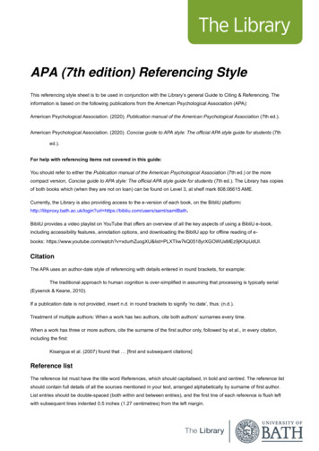
Example CalculationsThe below examples assume a ground reference is created by a proper transformerconfiguration and that the PV facility is interconnected to Xcel Energy’s 4‐wire electricdistribution system. For simplicity, the example online diagrams below exclude systemcomponents not relevant to grounding requirements; these drawings are not intended tobe used as example onelines for system design.Example 1 – Separate Zig‐Zag Grounding TransformerA PV facility with 1 MVA inverter total AC nameplate is interconnected to a 13.8kV feederthrough a 1 MVA interconnection transformer that does not create a ground reference. Aseparate zig‐zag transformer is connected at 13.8kV to meet ground referencingrequirements. (Note: Secondary ground bank connections are also acceptable when the interconnectiontransformer is wye‐grounded:wye‐grounded. The kV used for determinewould be 480V in that case.)i) Find base impedance:13.81190 ΩNotes: kV is high‐side voltage of grounding transformer.used for five 1 MVA facilities)Find zero‐sequence reactance requirement:0.6 190 Ω 10%,is aggregate facility (i.e. 5 MVA would be114 Ω10%The zig‐zag grounding transformer will require a per phase zero‐sequence reactance of114 Ω 10% to meet Requirement 1.ii) For Requirements 2, verify,4,iii) For Requirement 3, assuming4%.associate with114 Ω determines the continuous current,Find base current value. ΩBy:Date11‐18‐15Apv’d:PLDPrev: N/AVer: 1.441.8PV Ground Referencing EDEDOC#:Requirements andSample CalculationsPage:SPAE‐DG‐23 of 8
Find per unit zero sequence current., .0.067 . .Find zero sequence current in amps , .41.8 0.067 2.8Verify that the transformer per phase rating exceeds this value.Find neutral current33 2.88.4Verify that the transformer continuous neutral rating exceeds this value.iv) For Requirement 4, request system impedance from the Area engineer and determineground bank’s short circuit contribution for close‐in single‐line‐to‐ground faults. Thegrounding transformer 5‐second withstand rating shall exceed the maximum anticipatedground fault current contribution from the transformer.By:Date11‐18‐15Apv’d:PLDPrev: N/AVer: 1.4PV Ground Referencing EDEDOC#:Requirements andSample CalculationsPage:SPAE‐DG‐24 of 8
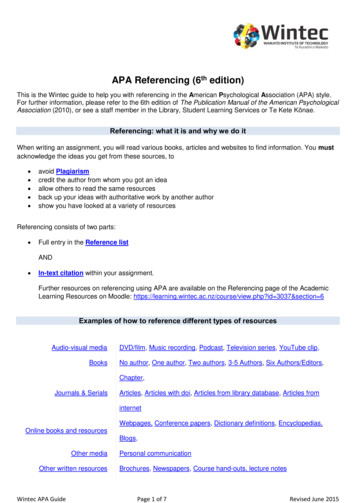
Example 2 – Wye‐grounded:Delta Interconnection Transformer with Neutral ReactorA PV facility with 1 MVA inverter total AC nameplate is interconnected to a 13.8kV feederthrough a 1 MVA interconnection transformer through a wye‐grounded:deltainterconnection transformer (grounded‐wye winding is connected to 13.8kV system). Theinterconnection transformer has nameplate impedance of 5%. A neutral reactor is requiredto meet ground referencing requirements.i) Find base impedance:13.81190 ΩNotes: kV is high‐side voltage of grounding transformer.used for five 1 MVA facilities)is aggregate facility (i.e. 5 MVA would beFind zero‐sequence reactance requirement:0.6 190 Ω 10%,114 Ω10%Find interconnection zero‐sequence reactance contribution: 0.05 190 Ω,,,9.5 ΩFind neutral reactor zero‐sequence contribution to meet requirement by subtractinginterconnection transformer contribution:114 9.5 Ω 104.5 Ω 10%,,,Determine neutral reactor size (note:3 104.5 Ω3,3,34.8 Ω):10%A neutral reactor with reactance of 34.8 Ω 10%, inserted into the neutral of theinterconnection transformer, will meet ground referencing Requirement 1. Requirements 2through 4 should be checked using transformer nameplate information.ii) For Requirements 2, verify,iii) For Requirement 3, assumingassociate with4%.By:Date11‐18‐15Apv’d:PLD4,,Prev: N/AVer: 1.4114 Ω determines the continuous currentPV Ground Referencing EDEDOC#:Requirements andSample CalculationsPage:SPAE‐DG‐25 of 8
Find base current value. 41.8ΩFind per unit zero sequence current., .0.067 . .Determine zero sequence current in amps , .41.8 0.0672.8Find neutral reactor current33 2.88.4Verify that the neutral reactor continuous rating exceeds this value.iv) For Requirement 4, request system impedance from the Area engineer and determineground bank’s short circuit contribution for close‐in single‐line‐to‐ground faults. Thegrounding transformer 5‐second withstand rating shall exceed the maximum anticipatedground fault current contribution from the transformer.By:Date11‐18‐15Apv’d:PLDPrev: N/AVer: 1.4PV Ground Referencing EDEDOC#:Requirements andSample CalculationsPage:SPAE‐DG‐26 of 8
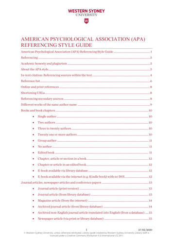
Example 3 – Separate Wye‐grounded:Delta Grounding TransformerA PV facility with 1 MVA inverter total AC nameplate is interconnected to a 13.8kV feederthrough a 1 MVA wye‐grounded:wye‐grounded interconnection transformer. A separatewye‐grounded:delta transformer is connected at 480V to meet ground referencingrequirements.i) Find base impedance:0. 4810.2304 ΩNotes: kV is high‐side voltage of grounding transformer.used for five 1 MVA facilities)is aggregate facility (i.e. 5 MVA would beFind zero‐sequence reactance requirement:0.6 0.23 Ω 10%,0.14 Ω10%The grounding transformer will require a per phase zero‐sequence reactance of0.14 Ω 10% to meet Requirement 1.ii) For Requirements 2, verify,4,iii) For Requirement 3, assumingassociate with4%.0.14 Ω determines the continuous current,Find base current value. .Ω1202.8Find per unit zero sequence current., .0.067 . .Find zero sequence current in amps , .1202.8 0.067 80.6Verify that the transformer per phase rating exceeds this value.By:Date11‐18‐15Apv’d:PLDPrev: N/AVer: 1.4PV Ground Referencing EDEDOC#:Requirements andSample CalculationsPage:SPAE‐DG‐27 of 8
Find neutral current33 80.6241.8Verify that the transformer continuous neutral rating exceeds this value.iv) For Requirement 4, refer to the system impedance from the Engineering Scoping StudyResults and determine ground bank’s short circuit contribution for close‐in single‐line‐to‐ground faults. Alternatively this may be requested from Area Engineering. The groundingtransformer 5‐second withstand rating shall exceed the maximum anticipated ground faultcurrent contribution from the transformer.By:Date11‐18‐15Apv’d:PLDPrev: N/AVer: 1.4PV Ground Referencing EDEDOC#:Requirements andSample CalculationsPage:SPAE‐DG‐28 of 8
through a 1 MVA interconnection transformer through a wye‐grounded:delta interconnection transformer (grounded‐wye winding is connected to 13.8kV system). The interconnection transformer has nameplate impedance of 5%. A neutral reactor is required to meet ground referencing requirements. i) Find base impedance: » Ô æ Ø G 8 6 / 8 # É .