Transcription
T. ElguedjabqNURBS09/12/2012ECCOMAS 2012Abaqus User Element implementation ofNURBS based Isogeometric AnalysisT. Elguedj1 ,A. Duval1 ,F. Maurin1 ,H. Al Akhras11 Université de Lyon, CNRSINSA-Lyon, Laboratoire de Mécanique des Contacts et des Structures, France6th European Congress on Computational Methods in Applied Science andEngineeringVienna, Austria – Sep. 10th - Sep. 14th 20121 / 22
T. ElguedjabqNURBS09/12/2012ECCOMAS 2012Outline1 Introduction2 ImplementationFEA vs. IGAMultiple patchesInput filesProcedure and GUI3 Numerical examplesLinear elasticityNonlinear material models4 Conclusions and future work2 / 22
T. ElguedjabqNURBS09/12/2012ECCOMAS 2012OutlineIntroductionImplementationFEA vs. IGAMultiple patchesInput filesProcedure and GUINumericalexamplesLinear elasticityNonlinear materialmodelsConclusions1 Introduction2 ImplementationFEA vs. IGAMultiple patchesInput filesProcedure and GUI3 Numerical examplesLinear elasticityNonlinear material models4 Conclusions and future work3 / 22
T. ElguedjabqNURBS09/12/2012ECCOMAS 2012IntroductionIntroductionImplementationFEA vs. IGAMultiple patchesInput filesProcedure and GUINumericalexamplesLinear elasticityNonlinear materialmodelsConclusionsIsogeometric Analysis is based on thegeometric primitives of CAD: NURBS andT-splines. It includes standard FEA as aspecial case, but offers other possibilities:Precise and efficient geometricmodelingSimplified mesh refinementSmooth basis functions with compactsupportSuperior approximation propertiesAccurate derivatives and stressesIntegration of design and analysis4 / 22Application in industry requires itsimplementation in commercial software
T. ElguedjabqNURBS09/12/2012ECCOMAS 2012IntroductionIntroductionImplementationFEA vs. IGAMultiple patchesInput filesProcedure and GUINumericalexamplesLinear elasticityNonlinear materialmodelsConclusionsSeveral commercial FE packages provide user element capabilities.Abaqus User ELement and User ELement with abaqus MATerialsubroutine offers the possibility to introduce arbitrary elements intoabaqus using user defined material models (UEL) or most of thematerial models available in the software (UELMAT).UEL can be defined with arbitrary shape functions, node numbers,polynomial order and integration points.All the standard finite element data can be passed in the .inp inputfile.Additional data can be passed as common variables using UserEXTERNAL DataBase (UEXTERNALDB) routines.5 / 22
T. ElguedjabqNURBS09/12/2012ECCOMAS 2012OutlineIntroductionImplementationFEA vs. IGAMultiple patchesInput filesProcedure and GUINumericalexamplesLinear elasticityNonlinear materialmodelsConclusions1 Introduction2 ImplementationFEA vs. IGAMultiple patchesInput filesProcedure and GUI3 Numerical examplesLinear elasticityNonlinear material models4 Conclusions and future work6 / 22
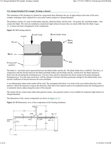
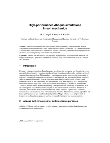
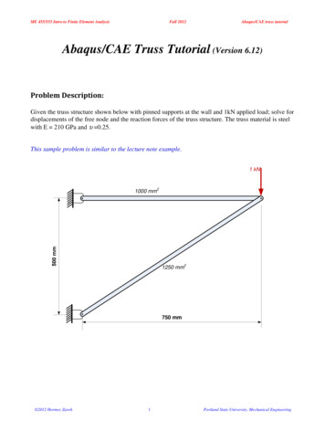
T. ElguedjabqNURBSP1: ABC/ABCP2: c/dc03JWBK372-CottrellQC: e/fT1: gMay 20, 200915:2209/12/2012Printer Name: Yet to ComeECCOMAS 2012Single patch implementationNURBS as a Basis for Analysis95IntroductionImplementationFEA vs. IGAMultiple patchesInput filesProcedure and GUINumericalexamplesLinear elasticityNonlinear materialmodelsStartLoop through elementsRead inputdataKe 0 and Fe 0Build connectivities and allocateglobal arraysK 0 and F 0Loop through quadraturepointsEvaluate basis functionsand derivativesAdd contributions toKe and FeConclusionsSolve Kd FWriteoutput dataAssemble Ke Kand Fe FStopFigure 3.15 Flowchart of a classical finite element code. Such a code can be converted to a single-patch7 / 22isogeometric analysis code by replacing the routines shown in green.J.A. Cottrell,T.J.R. Hughes, Y. Bazilevs Isogeometric Analysis, 2009.
T. ElguedjabqNURBS09/12/2012ECCOMAS 2012FEA vs. IGA dataIntroductionImplementationFEA vs. IGAMultiple patchesInput filesProcedure and GUINumericalexamplesLinear elasticityNonlinear materialmodelsFinite Element AnalysisNURBS based IGAnode coordinatescontrol points coordinateselement typepolynomial degreeelement connectivity (ID, IENand LM)element connectivity (ID, IEN,LM, INC)integration ruleintegration rulecontrol points weightsConclusionsknot vectorsCommon data can be passed in the .inp abaqus input file. We onlyconsider same polynomial order in all parametric directions, thereforeelement type defines the degree. Gauss quadrature is defined a priori basedon element type.8 / 22
T. ElguedjabqNURBS09/12/2012ECCOMAS 2012ConnectivityIntroductionImplementationFEA vs. IGAMultiple patchesInput filesProcedure and GUINumericalexamplesLinear elasticityNonlinear materialmodelsGiven a basis function (i.e. control point) number and a parametricdirection, the INC array returns the NURBS coordinate.Given a local basis function number and element number, the IENarray returns the global basis function number.Given a global basis function number and degree of freedom number,the ID array returns the equation number.ConclusionsThe IEN array is directly passed in the .inp file with the standardelement connectivity.The ID array is generated by abaqus based on the boundaryconditions and number of DOF per CP.9 / 22
T. ElguedjabqNURBS09/12/2012ECCOMAS 2012ConnectivityIntroductionImplementationFEA vs. IGAMultiple patchesInput filesProcedure and GUINumericalexamplesLinear elasticityNonlinear materialmodelsConclusionsGiven a basis function (i.e. control point) number and a parametricdirection, the INC array returns the NURBS coordinate.Given a local basis function number and element number, the IENarray returns the global basis function number.Given a global basis function number and degree of freedom number,the ID array returns the equation number.The INC array is used in the pre-processing step to construct IEN butonly a part of it is necessary in the shape function routine. For eachelement and parametric direction we only need the NURBScoordinate of the first local basis function. We replace INC by a newarray called NIJK.Given an element number and a parametric direction, the NIJK arrayreturns the NURBS coordinate of the first local basis function.9 / 22
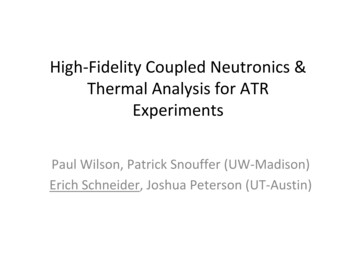
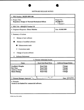
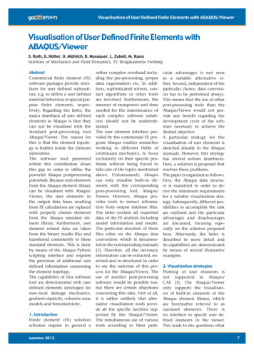
T. ElguedjabqNURBS96Isogeometric Analysis: Toward Integration of CAD and FEA09/12/20123.6.1.1 A multiple patch codeECCOMAS 2012A “multi-patch” isogeometric analysis code can be made to conform with the flowchart inFigure 3.15. In practice, however, it makes more sense to consider the slight modificationshown in Figure 3.16. In this case, we begin by inputting enough global information to buildthe global connectivities, as before. This information includes the polynomial orders and theknot vectors for each of the patches, but it does not require the control points. We can savetime and memory by not reading the control points until they are needed. If local refinementMulti-patch implementationIntroductionImplementationFEA vs. IGAMultiple patchesInput filesProcedure and GUINumericalexamplesLinear elasticityNonlinear materialmodelsStartLoop through patchesRead globalinput dataRead patchinput dataBuild connectivities and allocateglobal arraysLoop through elementson the current patchKe 0 and Fe 0K 0 and F 0Loop through quadraturepointsConclusionsEvaluate basis functionsand derivativesAdd contributions toKe and FeSolve Kd FWriteoutput dataStop10 / 22Assemble Ke Kand Fe F
which we insert into (3.58) along with w ! D 0 to arrive at !" w · u d" !"w f d" !!Rwr d! β!T. Elguedj!Rwu d! 0.(3.61) abqNURBS09/12/2012Though we have replaced one expression involving the unknown u for another, we haveenforced the relationship between them weakly.ECCOMAS 20123.5 Multiple patches revisitedMulti-patch3.5.1 Local FEA vs. IGAMultiple patchesInput filesProcedure and GUINumericalexamplesLinear elasticityNonlinear materialmodelsConclusions10 / 22In Section 3 of Chapter 2 we discussed the need for modeling domains using multiple patches.We always assume compatible discretizations for the geometry, meaning that on the coarsestmesh, mappingson the adjoiningfaces areidentical. abaqus.Each controlThe outerloop andonparameterizationspatches cannotbepatchusedwithinpoint on a face is in one-to-one correspondence with a control point from the adjoining face,0 In many instances, this relationship will belikewiseforthecontrolvariablesofthesolution.For simplicity we only support C coupling with conforming meshes.preserved as we refine. To make the assembly of the stiffness matrices and force vectors assimple as possible, theconnectivityidentify the equivalentlocal control variablesThe connectivityarraysforarrayallwillpatchesare generatedin theon each face with a single control variable in the global array. By identifying them as a singlepre-processingstep.entity for analysispurposes, we simplify the logic and decrease the total amount of workneeded. The result is that the two patches are joined as though they were one.control points at ofthe samein physical spacebeing a singlepointsentityThen a Identifyingglobal tworeorderingthelocationelementsandascontrolis doneis fairly trivial. Slightly subtler is what this implies for the basis functions. The situation iswith a shownmergingof WhenCPtwoonbasespatchin Figure 3.7.generatedinterfaces.using open knot vectors are brought together,the effect is indistinguishable from the case of one knot vector with a knot repeated p times,The rexactlya single patch.as longas theof the twoforjoiningfunctionsare the domainsame. This is, ofwhat we have assured by identifying the two control variables as one.Patch data is passed in the .NB file.Figure 3.7 If two knot vectors formed from open knot vectors are brought together, they can be made
T. ElguedjabqNURBS09/12/2012ECCOMAS 2012.inp fileIntroductionImplementationFEA vs. IGAMultiple patchesInput filesProcedure and GUINumericalexamplesLinear elasticityNonlinear materialmodelsConclusions11 / 22*HEADING**Job name:test.txt**abqNURBS - Laboratoire de Mecanique des Contacts et des Structures - INSA-Lyon*Part, name Piece*USER ELEMENT, NODES ncpelt, TYPE Up, COORDINATES d, variables size of SVARS,INTEGRATION ngelt, TENSOR PSTRAIN or THREED1,2 for 2D, 1,2,3 for 3D*Node,nset AllNode - list of control pointscpnb, X-coordinate, Y-coordinate, Z-coordinate*Element, type Up, elset AllEls - list of elementseltnb, CP1, CP2, CP3, .*ELSET,ELSET EltPAtch1 - set of all the elementslist of elements nb*NSET,NSET SetCPFacei - set of control points used for Dirichlet BClist of control points lying on the i-th face*ELSET, ELSET SetEltFacei - set of elements used for Neumann BClist of elements belonging to the i-th face*UEL PROPERTY, ELSET EltPatch1, MATERIAL MAT - assign the material to the set of all elements*End Part** ASSEMBLY*Assembly, name Assembly*Instance, name I1, part Piece*End Instance*End Assembly
T. ElguedjabqNURBS09/12/2012ECCOMAS 2012.inp fileIntroductionImplementationFEA vs. IGAMultiple patchesInput filesProcedure and GUINumericalexamplesLinear elasticityNonlinear materialmodelsConclusions11 / 22**MATERIAL*MATERIAL,NAME MAT*ElasticYoung’s modulus value, Poisson’s ratio value*STEP,extrapolation NO,NLGEOM YES or NO*Static** BOUNDARY CONDITIONS - list of Dirichlet boundary conditions*BoundaryI1.SetCPFacei, direction of the imposed BC, direction of the imposed BC, value imposed.** LOADS - list of Neumann boundary conditions*CloadI1.SetFacei, key for selecting element face, value imposed.** OUTPUT REQUESTS*node file, frequency 1U,RF,CF*el file, frequency 1SDV*End Step
T. ElguedjabqNURBS09/12/2012ECCOMAS 2012.NB fileIntroductionImplementationFEA vs. IGAMultiple patchesInput filesProcedure and GUINumericalexamplesLinear elasticityNonlinear materialmodelsConclusions12 / 22*DIMENSION2 or 3* total nb of elementsnelt*nb of patchesnbpatch*nb of elements per patchneltp1, neltp2, .*data for patch inumber of knots for parametric direction jknot vector for parametric direction j*NIJK array based on global domain element numberingeltnb, nijk1, nijk2, nijk3*list of CP weights based on global domain CP numberingCPnb, weight
T. ElguedjabqNURBS09/12/2012ECCOMAS 2012ProcedureIntroductionImplementationFEA vs. IGAMultiple patchesInput filesProcedure and GUINumericalexamplesLinear elasticityNonlinear materialmodelsConclusions13 / 221 Pre-processingMatlab pre-processor based on Geopdes. Handles 2D, 3D singleand multi-patch cases.Rhino plugin for multi-patch 2D cases (imposition of BC,material definition).2 Analysis3 Post-processing
T. ElguedjabqNURBS09/12/2012ECCOMAS 2012ProcedureIntroductionImplementationFEA vs. IGAMultiple patchesInput filesProcedure and GUINumericalexamplesLinear elasticityNonlinear materialmodelsConclusions13 / 221 Pre-processing2 AnalysisGUI for selecting IGA input files.Interactive job execution using our IGA user element.3 Post-processing
T. ElguedjabqNURBS09/12/2012ECCOMAS 2012ProcedureIntroductionImplementationFEA vs. IGAMultiple patchesInput filesProcedure and GUINumericalexamplesLinear elasticityNonlinear materialmodelsConclusions13 / 221 Pre-processing2 Analysis3 Post-processingRequest output of the results in a raw ASCII file .fil (CP data,internal variables).GUI user interface for selecting input and output files andpost-processing parameters.Abaqus python and C scripting interface to performprojection on a finer FE mesh. (Internal variables are firstprojected onto CP using global least-square if needed).Generate a projected output database binary file .odb readablein abaqus CAE.
T. ElguedjabqNURBS09/12/2012ECCOMAS 2012Graphical User InterfaceIntroductionImplementationFEA vs. IGAMultiple patchesInput filesProcedure and GUINumericalexamplesLinear elasticityNonlinear materialmodelsConclusionsmovie14 / 22
T. ElguedjabqNURBS09/12/2012ECCOMAS 2012OutlineIntroductionImplementationFEA vs. IGAMultiple patchesInput filesProcedure and GUINumericalexamplesLinear elasticityNonlinear materialmodelsConclusions1 Introduction2 ImplementationFEA vs. IGAMultiple patchesInput filesProcedure and GUI3 Numerical examplesLinear elasticityNonlinear material models4 Conclusions and future work15 / 22
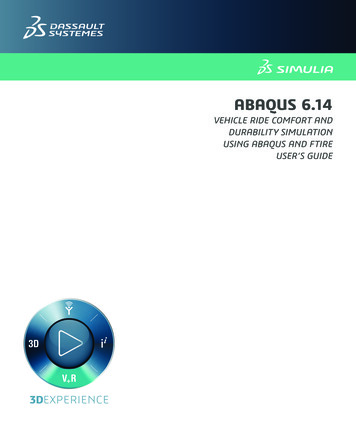
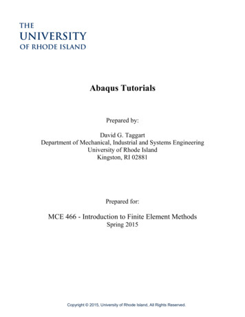
T. ElguedjabqNURBS09/12/2012ECCOMAS 2012Linear elasticity: single patch horseshoeIntroductionImplementationFEA vs. IGAMultiple patchesInput filesProcedure and GUINumericalexamplesLinear elasticityNonlinear materialmodelsConclusionsE 100 000MPa, ν 0.3, imposed displacement of ud / 1ex .16 / 22T.J.R. Hughes, J.A. Cottrell, Y. BazilevsIsogeometric analysis: CAD, finite elements, NURBS, exact geometry andmesh refinement. Computer Methods in Applied Mechanics andEngineering, vol. 194, p. 4135–4195, 2005.
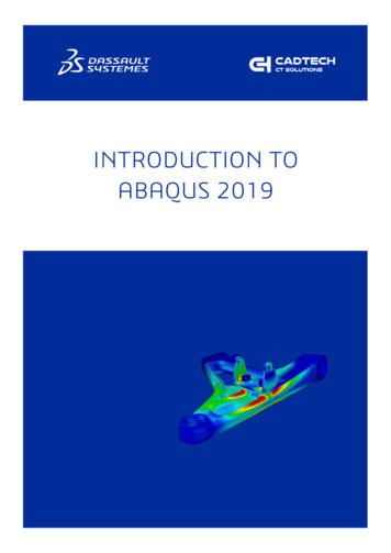
T. ElguedjabqNURBS09/12/2012ECCOMAS 2012Linear elasticity: single patch horseshoe (cont’d)IntroductionImplementationFEA vs. IGAMultiple patchesInput filesProcedure and GUINumericalexamplesLinear elasticityNonlinear materialmodelsConclusionsσzz on initial configuration17 / 22σzz on deformed configuration
T. ElguedjabqNURBS09/12/2012ECCOMAS 2012Linear elasticity: multipatch cylinderIntroductionImplementationFEA vs. IGAMultiple patchesInput filesProcedure and GUICylinder submitted to internal pressure, geometry defined with 4 patches.R 2m, r 1m, E 100000MPa, ν 0.3, p 10MPa.NumericalexamplesLinear elasticityNonlinear materialmodelsConclusionsVon Mises stress on deformedconfiguration18 / 22undeformed geometry and mesh.
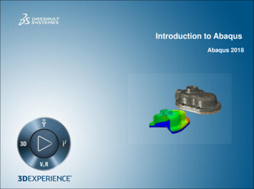
T. ElguedjabqNURBS09/12/2012ECCOMAS 2012Small strain plasticity: plane strain cylinderIntroductionImplementationFEA vs. IGAMultiple patchesInput filesProcedure and GUICylinder submitted to internal pressure, elastic vs. perfectly plastic case.R 2m, r 1m, E 200000MPa, ν 0.3, σy 200MPa, p 145MPa.NumericalexamplesLinear elasticityNonlinear materialmodelsConclusionsVon Mises stress pure elastic caseminM AX(σvm 85MPa ; σvm 335MPa)19 / 22Von Mises stress perfectly plasticmincase (σvm 116MPa ;M AXσvm 200MPa)
T. ElguedjabqNURBS09/12/2012ECCOMAS 2012OutlineIntroductionImplementationFEA vs. IGAMultiple patchesInput filesProcedure and GUINumericalexamplesLinear elasticityNonlinear materialmodelsConclusions1 Introduction2 ImplementationFEA vs. IGAMultiple patchesInput filesProcedure and GUI3 Numerical examplesLinear elasticityNonlinear material models4 Conclusions and future work20 / 22
T. ElguedjabqNURBS09/12/2012ECCOMAS 2012ConclusionsIntroductionImplementationFEA vs. IGAMultiple patchesInput filesProcedure and GUINumericalexamplesLinear elasticityNonlinear materialmodelsConclusionsWe have a proposed an implementation of NURBS based IGA in theabaqus FEA commercial package.The implementation is able to handle single and multiple patches (C 0continuity across compatible patch boundaries).Thank to UELMAT we can directly use most material modelsavailable in abaqus for small and large deformation (NLGEOM).Post processing capabilities are available directly into abaqus CAEusing Python/C scripting interface.Preliminary work on pre-processing allow us to provide a GUI for 2Dcases and matlab for 3D.21 / 22
T. ElguedjabqNURBS09/12/2012ECCOMAS 2012Future workIntroductionImplementationFEA vs. IGAMultiple patchesInput filesProcedure and GUINumericalexamplesLinear elasticityNonlinear materialmodelsConclusionsImprove the way necessary extra data can be passed on (i.e. outsidethe .inp file).Introduce Bezier extraction as an alternative.Include temperature for thermal or thermo-mechanical analysis,further test NLGEOM and material models as well as dynamics.Released as open source under the CeCILL license in a few days.http://abqnurbs.insa-lyon.fr22 / 22
Abaqus User ELement and User ELement with abaqus MATerial subroutine o ers the possibility to introduce arbitrary elements into abaqus using user de ned material models (UEL) or most of the material models available in the software (UELMAT). UEL can be de ned with arbitrary shape functions, node numbers, polynomial order and integration points.