Transcription
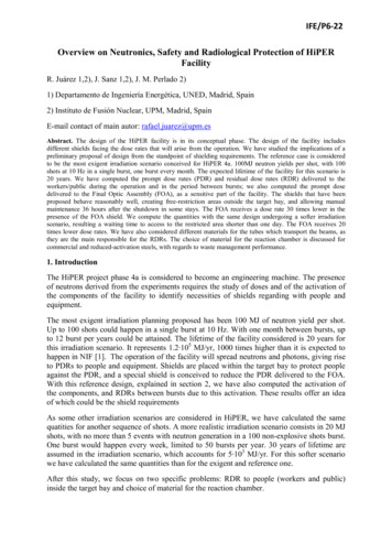
High‐Fidelity Coupled Neutronics &Thermal Analysis for ATRExperimentsPaul Wilson, Patrick Snouffer (UW‐Madison)Erich Schneider, Joshua Peterson (UT‐Austin)
Acknowledgements This work was funded by the ATR NSUFFaculty Student Team Project Program Thanks to INL staff who supported ourproject:– Jim Parry– Glenn Roth– Scott Davis– Jeff Benson
Motivation Create a fast, simple method for experimenters tocharacterize NSUF experiments with minimaldependence on INL staff– focus: support the proposal‐writing stage of experimentdesign– fidelity: 10% deviation in major experiment metrics versusfull radiation transport analysis– ease of use: MCNP5 and CAD‐to‐DAGMC support, users needonly create a stand‐alone CAD model of the experimentalposition Direct use of CAD model for analysis Simplified neutronics modeling without full core (Semi‐) automated coupling between neutronics and thermal analysis
WorkflowLook up nuclearresponse inmaterial database1‐D or0‐D ExcelSpreadsheet Analysis
SInput FileMCNP5InputABAQUSABAQUSOutput Filew/ thermalresponse
ires eithersubstantial simplificationorlarge investmentin human effortABAQUSABAQUSABAQUSInput FileCAESkill set unique to nuclear engineeringABAQUSOutput Filew/ thermalresponse
WorkflowManual transfer of heating data fromMCNP5MCNP5MCNP‐ ABAQUSMCNP5InputInputRequiressubstantial simplificationand/orloss of fidelityGeometryModelABAQUSCAEABAQUSInput FileABAQUSABAQUSOutput Filew/ thermalresponse
tryCUBITMCNP5 HeatingMesh TalliesMCNP5InputSolid SSARSSAABAQUSCAEABAQUSInputFileABAQUS Input Filew/ per elementheatingMOAB MeshInterpolationABAQUSABAQUSOutput File w/thermalresponse
Workflow ComponentsGeometry: DAG‐MCNP5 to the ATR or componentNeutronic Analysis:Surface Source ApproachThermal Analysis: MCNP5‐ ABAQUS Translation
Geometry: CAD‐to‐MCNP5 The CAD‐to‐MCNP5 process involves foursteps:1. Create geometry in 3D CAD software (e.g.SolidWorks) from a provided template2. Import geometry into Cubit to imprint, merge,and add materials (scripted step involvingminimal user interactions)3. Add tallies to MCNP5 template (optional) andexecute DAGMC (Direct Accelerated Geometry MonteCarlo) (requires MCNP5 template and Cubit‐prepared geometry)4. (optional) visualize mesh tally results in VISIT
Step 1: Create Geometry in 3D CAD Most CAD systems will work for creating the initial model. Thescreenshot is taken from a SolidWorks full‐core ATR model Individual parts are associated with material, tally andexperiment tags via a naming convention It is important that the model has no overlapping surfaces
Step 2: Import into Cubit An ‘automated’ step (via script files) that translates the CADmodel into the ACIS format suitable for reading by DAGMC
Step 3: Run Radiation TransportSimulation: DAGMC DAGMC accomplishes ray tracing directly on CAD‐based solidmodels, without translation to MCNP5 input language. DAGMCemploys high‐fidelity faceting combined with hierarchical trees oforiented bounding boxes for those facets. To execute DAGMC, the user must– prepare an MCNP input file including only the third block, the data cards. no cell or surface cards are required– Run DAG‐MCNP5, specifying the geometry and MCNP5 file names and(optional) faceting tolerance, as well as the output facet file name DAGMC supports parallel execution and tallies via– “groups” created by the user within CUBIT– direct tally specification in the MCNP data block. Heating mesh tallies serve as input to part 3 of the workflow(ABAQUS thermal modeling)
Step 4: Viewing Results in Visit
Neutronic Analysis: Surface Source“Substitution” Approach Overview of two surface source read/write(SSR/W) techniques (both available to users;substitution technique is the focus here)– Idea: use MCNP5 RSSA files to impose boundaryconditions at experiment positions Analyses can be carried out– stand‐alone: create geometries within MCNP5– from CAD‐software via interface to DAGMC. Users write their own reaction rate tallies(exception: heating mesh tallies)
Substitution Approach, Step 1KCODE (eigenvalue)calculation on full corewith representativespecimens (surrogates) inexperiment positionUse SSW to write tosurface(s) enclosingposition (as many meanfree paths from the trapas feasible)
Substitution Approach, 2This step is completed byusers. The model supplied toyou (CAD & MCNP5) consistsonly of the region inside SSRsurfaces.You create your experimentgeometries (in MCNP5 or CADvia DAGMC) and run anMCNP5 transport calculationusing surface sources (RSSAfiles) we supply.
Products Software products include– Surface source (RSSA) files ready to be read by MCNP5;– MCNP5 ‘template’ decks for experiment positions;– SolidWorks ‘template’ files for experiment positions. Software is available for– large B (B11), small B (B5), an inner and outer A,center, south and southwest flux traps. User guide includes walkthrough for using RSSA filesand MCNP5 decks
Thermal Analysis: Coupling DAGMCto ABAQUS
WorkflowCAD modelCubitMCNP Describe geometry Add material tags Imprint/Merge Assign materials Vacuum Define materials Import Source Mesh talliesMOABAbaqusAbaqus Tetrahedral mesh Create assembly Import materials Common mesh format Interpolate betweenmeshes Fine resolutionheat flux
Motivation Automate assignment of heat fluxesin Abaqus: support arbitrary mesh resolution (DAG)MCNP heating data supplied viaenergy deposition mesh tallies Use the same geometric model inall steps of the analysis
MOAB Mesh Oreiented dAtaBase Used here to convert between two meshes Interfaces with many different packages: Visit MCNP ExodusII Cubit Native mesh translator included tointerpolate MCNP tally geometry onto Abaqusmesh
Mesh Interpolation Run MCNP with heating mesh tally and import mesh tally andAbaqus mesh into MOAB Via MOAB the problem depicted below is resolved to obtainvolumetric power deposition for each Abaqus mesh element:
Interpolation ‐ The ProblemMCNP mesh elementMat 1 Both mat1 and mat2contribute to the energydeposition reported in theMCNP mesh tally: the MCNP mesh tally reflectsvolume‐weighted contributionsfrom each material, but Mat 2 each element in Abaqus(green/orange shaded areas) isonly comprised of onematerial
Interpolation – Solution Create one MCNP mesh tally foreach material in the geometryMCNP mesh tally mat1MCNP mesh tally mat2‐ MCNP computes the powerdeposition as if the entire geometrywere filled with that material,independently from its radiationtransport calculation Obtain heat flux in each Abaqusnode from the mesh tally generatedfor the material in that abaqus node(red and blue in the illustration)Abaqus nodes
Process for Abaqus Analysis Import CAD geometry Add meshes, and create/assign materials Create assembly Write .inp file and read into MOAB Run scripts to interpolate MCNP meshtallies onto Abaqus mesh Write heat data to .inp file Add any ancillary inputs to Abaqus model Run Abaqus
Resources / References DAGMC– to obtain DAGMC, please visit i?p DirectAcceleratedGeometryMonteCarlo– this site also features walkthroughs for installation, configuration andexecution of the software– it also provides links to sites hosting the applications MOAB and CUBIT Full documentation of the workflow and a detailed step‐by‐stepwalkthrough may be found in:– P.P.H. Wilson, P. Snouffer, E.A. Schneider, J.L. Peterson, ”Demonstrating High‐FidelityCoupled Neutronic and Thermal Analysis of ATR Experiments: A 2009 ATR FacultyStudent Research Team Project,” technical report (2009). For theoretical background and benchmarking studies on thesurface‐source method, see– P.P.H. Wilson, P. Snouffer, E.A. Schneider, J.L. Peterson, “A Monte Carlo Surface SourceMethod for Advanced Test Reactor Experiment Prototyping,” Proc. PHYSOR 2010,Pittsburgh, PA, May (2010).
Neutronic Analysis: SupplementalInformation Overview of two surface source read/write(SSR/W) techniques (both available to users)– Idea: use MCNP5 RSSA files to impose boundaryconditions at experiment positions Refinement of methods via simulation ofexisting experiments Benchmarking and validation– full transport (eigenvalue calculation) versusSSR/W techniques
SSW/R Techniques: SubstitutionApproach, Step 1KCODE (eigenvalue)calculation on full corewith representativespecimens (surrogates) inexperiment positionUse SSW to write tosurface(s) enclosingposition (as many meanfree paths from the trapas feasible)
Substitution Approach, 2This step is completed byusers. The model supplied toyou consists only of the regioninside SSR surfaces.You create your experimentgeometries (in MCNP5 or CADvia DAGMC) and run anMCNP5 transport calculationusing surface sources (RSSAfiles) we supply.
Superposition Approach, Step 1A KCODE calculation is runon the full core model withdefault specimens inexperiment positionsThe MCNP5 SSW CELcommand is used to writethe fission neutron sourcedistribution. This step mustonly be done once.
Superposition Approach, 2SSR calculation on fullcore with nonu 0(fission neutrons notproduced; promptgammas produced) toread fission sourcedistributionUse SSW to writecrossings into test regionof zero importance (nextslide)
Superposition Approach, 2In this approach, it’sadvantageous to ‘bank’ onlyparticles crossing into theregion whose contentsmight change.Steps 1 and 2 are carried outin advance. The userperforms only Step 3:
Superposition Approach, 3You work with a full coremodel but only modify theregion within the SSRsurface(s).You run a fixed‐sourcecalculation using thesupplied RSSA file. nonu 0(no fission n produced)outside the SSR surface(s)and, if necessary, nonu 1(both n and γ produced)inside
Superposition: Summary Summing results of calculations 2) and 3) gives (approximate)full depiction of population in core– Like running 1 KCODE iteration– Can provide estimate of reactivity worth of experiment Advantageous to place SSR/SSW surface as close to samples aspossible– Substitution functions best when SSR/SSW is far from samples Substitution approach aims to capture inside‐of‐trap transporteffects of actual specimen through use of representativesurrogates Superposition eliminates the need for surrogates but thegeometry for the SSR run must extend well beyond theexperiment position
Refinement of Methods Issues we quantitatively investigated:– Substitution Importance of surrogate Sensitivity to size of ‘cutout’ region– Superposition Comparison to substitution method– Both Applicability to photon as well as neutron transport Approach: study existing experiments in avariety of locations, quantify fidelity level
Qualitative Experiment‘Categories’The fidelity of the substitution approach depends on the choiceof surrogate. A surrogate that is qualitatively similar to theexperiment being analyzed would be expected to affect the fluxat the SSR/W boundary in a similar way.We defined the following four categories and identifiedsurrogates for each from a pool of existing experiments:Strong ThermalAbsorber AbsentStrong ThermalAbsorber PresentMultiplying MediumAbsentAluminum filler rodsHafnium aluminideexperimentMultiplying MediumPresentAFIP experimentAFCI experiment (withCd)
Experiment ModelsAFCI Metallic FuelATR Full Size Plates(AFIP)To investigate theeffectiveness of thesurrogate approach,additional experimentswere modeled andclassified by ‘category.’These were used toquantify the sensitivity ofthe substitution method tosurrogate ‘category.’Advanced GasReactor (AGR)FuelGraphiteIrradiationCreep Capsule(AGC‐1)
Sensitivity Studies: Surrogates and RadiiNon‐multiplying, non‐absorbingSurrogateTrialAluminum filler rodsGraphite pins (AGC‐1)Non‐multiplying, absorbing Hafnium aluminideexperimentCobalt rodletsMultiplying, non‐absorbingAFIP experimentAGR experimentMultiplying, absorbingAFCI experiment (with Cd)AGR experiment withhafnium shellOuter A Position: CandidateSurface Source Locations (5)Large BPosition:CandidateSurface SourceLocations (2)
Surrogate & SSW/R Radius ICobalt rodlets experiment. The qualitatively ‘close’ surrogate is Hf, whichshows the best agreement at both radii for the substitution approach.Superposition performs well at all flux traps as well as positions fartherfrom the fuel.
Surrogate & SSW/R Radius IIAGR experiment, no Hf sheath. The figures on this and the next slideillustrate the critical role of the surrogate in the substitution approach,particularly if the volume enclosed by the SSW/R is small. Here the AFIPsurrogate is expected to be best.Surrogate / radius [cm]
Surrogate & SSW/R Radius IIIAGR experiment, Hf sheath. When the sheath is included, the AFCI surrogateis expected to be most appropriate (and on this occasion, it proves to be thecase). Note that the smaller SSW/R (dimension chosen to avoid cutting theadjacent control drum) remains extremely sensitive to surrogate choice.Surrogate / radius [cm]
These tables integrateall experiment /surrogate / radiusstudies performed forthe large B position:ExperimentsLarge B positionsurrogate study Experiments(smaller SSW/Rradius: 2.9 cm)differences:(SSW – benchmark) /(benchmark)Color codes:Green: 10%Yellow: 10 – 20%Red: 5.52.014.8% difference in DPA in Iron at r 2.9 .215.15.116.1GraphiteAGRCoAGR(Hf)% difference in TOTAL power deposition at r 2.9 cm )% difference in capture rate at r 2.9 cm RCoAGR(Hf)% difference in fission rates r 2.9 cm 8.021.618.6n/an/an/an/a30.926.37.84.0
Large B positionsurrogate study(larger SSW/Rradius: 6.55 cm)ExperimentsExperimentsdifferences:(SSW – benchmark) /(benchmark)ExperimentsColor codes:Green: 10%Yellow: 10 – 20%Red: 20%ExperimentsGraphiteAGRCoAGR(Hf)Al1.11.90.22.6% difference in DPA in Iron at r 6.55 .81.06.9GraphiteAGRCoAGR(Hf)% difference in TOTAL power deposition at r 6.55 cm .65.44.86.81.51.41.71.54.0GraphiteAGRCoAGR(Hf)% difference in capture rate at r 6.55 cm Hf)% difference in fission rates r 6.55 cm .93.52.7n/an/an/an/a1.41.71.54.0
Conclusion Substitution works well ( 10% error)provided that surface source placed far(several mfp) from site of perturbation Superposition led to 10% error in allinvestigated cases, but requires that usersmanipulate the full‐core model Both approaches reduce execution times byabout two orders of magnitude (forcomparable statistics) as compared to a fullKCODE analysis
ABAQUS CAE ABAQUS. CAE. ABAQUS Input File ABAQUS Input File. ABAQUSABAQUS. ABAQUS Output File response w/ thermal response ABAQUS Output File w/ thermal. Geometry Model Geometry Model. MCNP5 Input MCNP5 Input. Requires either substantial simplification. or. large investment in human effort Skill set unique to nuclear engineering. Requires either