Transcription
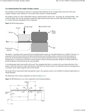
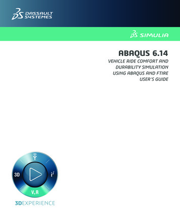
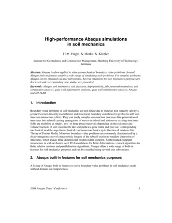
ME 455/555 Intro to Finite Element AnalysisFall 2012Abaqus/CAE truss tutorialAbaqus/CAE Truss Tutorial (Version 6.12)Problem Description:Given the truss structure shown below with pinned supports at the wall and 1kN applied load; solve fordisplacements of the free node and the reaction forces of the truss structure. The truss material is steelwith E 210 GPa and υ 0.25.This sample problem is similar to the lecture note example.1 kN1000 mm21250 mm2750 mm 2012 Hormoz Zareh1Portland State University, Mechanical Engineering
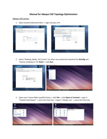
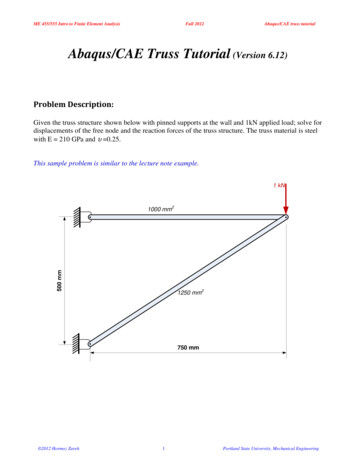
ME 455/555 Intro to Finite Element AnalysisFall 2012Abaqus/CAE truss tutorialAnalysis Steps1. Start Abaqus and chooseto create a new modeldatabase2. In the model tree double click on the “Parts” node (or right click on “parts” and select Create)3. In the Create Part dialog box (shown above) name the part anda. Select “2D Planar”b. Select “Deformable”c. Select “Wire”d. Set approximate size 1e. Click “Continue ” 2012 Hormoz Zareh2Portland State University, Mechanical Engineering
ME 455/555 Intro to Finite Element AnalysisFall 2012Abaqus/CAE truss tutorial4. Create the geometry shown below (details not discussed here)5. Double click on the “Materials” node in the model treea. Name the new material and give it a description 2012 Hormoz Zareh3Portland State University, Mechanical Engineering
ME 455/555 Intro to Finite Element AnalysisFall 2012Abaqus/CAE truss tutorialb. Click on the “Mechanical” tabÎElasticityÎElasticc. Define Young’s Modulus and Poisson’s Ratio (use base SI units)i. WARNING: There are no predefined system of units within Abaqus, so the user isresponsible for ensuring that the correct values are specifiedd. Click “OK” 2012 Hormoz Zareh4Portland State University, Mechanical Engineering
ME 455/555 Intro to Finite Element AnalysisFall 2012Abaqus/CAE truss tutorial6. Double click on the “Sections” node in the model treea. Name the section “HorizontalBar” and select “Beam” for both the category and “Truss” for thetypeb. Click “Continue ”c. Select the material created above (Steel)d. Set cross-sectional area 0.001 (base SI units, m2)e. Click “OK”f.Repeat for the “AngledBar”i. Cross-sectional area 0.001257. Expand the “Parts” node in the model tree, expand the node of the part just created, and double clickon “Section Assignments”a. Select the horizontal portion of the geometry in the viewportb. Click “Done”c. Select the “HorizontalBar” section created aboved. Click “OK”e. Repeat for the angled portion of the geometry 2012 Hormoz Zareh5Portland State University, Mechanical Engineering
ME 455/555 Intro to Finite Element AnalysisFall 2012Abaqus/CAE truss tutorial8. Expand the “Assembly” node in the model tree and then double click on “Instances”a. Select “Dependent” for the instance typeb. Click “OK” 2012 Hormoz Zareh6Portland State University, Mechanical Engineering
ME 455/555 Intro to Finite Element AnalysisFall 2012Abaqus/CAE truss tutorial9. Double click on the “Steps” node in the model treea. Name the step, set the procedure to “General”, and select “Static, General”b. Click “Continue ”c. Give the step a descriptiond. Click “OK” 2012 Hormoz Zareh7Portland State University, Mechanical Engineering
ME 455/555 Intro to Finite Element AnalysisFall 2012Abaqus/CAE truss tutorial10. Expand the Field Output Requests node in the model tree, and then double click on F-Output-1 (FOutput-1 was automatically generated when creating the step)a. Uncheck the variables “Strains” and “Contact”b. Click “OK”11. Expand the History Output Requests node in the model tree, and then right click on H-Output-1 (HOutput-1 was automatically generated when creating the step) and select Delete 2012 Hormoz Zareh8Portland State University, Mechanical Engineering
ME 455/555 Intro to Finite Element AnalysisFall 2012Abaqus/CAE truss tutorial12. Double click on the “BCs” node in the model treea. Name the boundary conditioned “Pinned” and select “Displacement/Rotation” for the typeb. Click “Continue ”c. Select the endpoints on the left (“shift” select ) and press “Done” in the prompt aread. Check the U1 and U2 displacements and set them to 0e. Click “OK” 2012 Hormoz Zareh9Portland State University, Mechanical Engineering
ME 455/555 Intro to Finite Element AnalysisFall 2012Abaqus/CAE truss tutorial13. Double click on the “Loads” node in the model treea. Name the load “PointLoad” and select “Concentrated force” as the typeb. Click “Continue ”c. Select the vertex on the right and press “Done” in the prompt aread. Specify CF2 -1000e. Click “OK” 2012 Hormoz Zareh10Portland State University, Mechanical Engineering
ME 455/555 Intro to Finite Element AnalysisFall 2012Abaqus/CAE truss tutorial14. In the model tree double click on “Mesh” for the Truss part, and in the toolbox area click on the“Assign Element Type” icona. Select “Standard” for element typeb. Select “Linear” for geometric orderc. Select “Truss” for familyd. Note that the name of the element (B21) and its description are given below the elementcontrolse. Click “OK” 2012 Hormoz Zareh11Portland State University, Mechanical Engineering
ME 455/555 Intro to Finite Element AnalysisFall 2012Abaqus/CAE truss tutorial15. In the toolbox area click on the “Seed Edges” icona. Select the entire geometryb. Choose method as “By number”c. Define the number of elements along the edges as “1”d. Click “OK”16. In the toolbox area click on the “Mesh Part” icona. Click “Yes” in the prompt area 2012 Hormoz Zareh12Portland State University, Mechanical Engineering
ME 455/555 Introo to Finite Elemennt AnalysisFall 20112AAbaqus/CAE trusss tutorial17. In the menu bar select ViewÎÎPart Displayy Optionsa.a On the Mesh tab checkk “Show nodee labels” and “Show elemeent labels”b.b Click “OK”” 2012 Hormoz Zareh13EngineeringPortlland State Universsity, Mechanical E
ME 455/555 Intro to Finite Element AnalysisFall 2012Abaqus/CAE truss tutorial18. In the model tree double click on the “Job” nodea. Name the job “Truss”b. Click “Continue ”c. Give the job a descriptiond. Click “OK” 2012 Hormoz Zareh14Portland State University, Mechanical Engineering
ME 455/555 Intro to Finite Element AnalysisFall 2012Abaqus/CAE truss tutorial19. In the model tree right click on the job just created (Truss) and select “Submita. While Abaqus is solving the problem right click on the job submitted (Truss), and select“Monitor”b. In the Monitor window check that there are no errors or warningsi. If there are errors, investigate the cause(s) before resolvingii. If there are warnings, determine if the warnings are relevant, some warnings can besafely ignored 2012 Hormoz Zareh15Portland State University, Mechanical Engineering
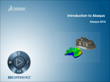
ME 455/555 Introo to Finite Elemennt AnalysisFall 20112AAbaqus/CAE trusss tutorial20. In the model tree right click ono the submittted and succ essfully comppleted job (Trruss), and seleect“Results”21. In the menu bar clickcon ViewpportÎViewpoort Annotatioons Optionsa.a Uncheck thet “Show coompass optionn”b.b The locatiions of viewpport items cann be specifiedd on the correesponding tabb in the ViewpportAnnotatioons Optionsc.c Click “OK””22. Displlay the deformmed contour of the (Von) Mises stress overlaid withh the undeforrmed geometrya.a In Abaquss 6.11 the deffault display fieldfoutput iss (Von) Misess stressb.b In the tooolbox area clicck on the folloowing iconsi. “PPlot Contourss on Deformeed Shape”ii. “AAllow Multiplle Plot States””iii. “PPlot Undeformmed Shape” 2012 Hormoz Zareh16EngineeringPortlland State Universsity, Mechanical E
ME 455/555 Intro to Finite Element AnalysisFall 2012Abaqus/CAE truss tutorial23. In the toolbox area click on the “Common Plot Options” icona. Note that the Deformation Scale Factor can be set on the “Basic” tabb. On the “Labels” tab check “Show element labels”, “Show node labels”, and “Show nodesymbols”i. *Note* the default label colors may need to be adjusted for visibility. They can bechanged in this option box by clicking on the color and picking a new one.c. Click “OK” 2012 Hormoz Zareh17Portland State University, Mechanical Engineering
ME 455/555 Intro to Finite Element Analysis 2012 Hormoz ZarehFall 201218Abaqus/CAE truss tutorialPortland State University, Mechanical Engineering
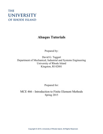
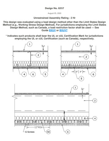
ME 455/555 Introo to Finite Elemennt AnalysisFall 20112AAbaqus/CAE trusss tutorial24. To determinedthe local stress values use thhe probe featture.a.a This can beb found in twwo locationsi. Inn the menu baar click ToolsÎQuery Æ PProbe Valuesii. Inn the vertical icon tool barb.b In the viewwport mousee over the element of interrestc.c Click on an element to store it in the “Selected PProbe Values”” portion of the dialogue bboxd.d Note thatt Abaqus repoorts stress vallues from thee integration ppoints, whichh may differ slightlyfrom the valuesvdetermmined by projjecting valuess from the surrounding inttegration points tothe nodessi. The minimum and maximum stress valu es contained in the legendd are from theodessttresses projeccted to the noii. The probe can be set to queery either thee elements orr nodes.e.e Click “Canncel” and there is no need to save the qqueried pointts at this timee. 2012 Hormoz Zareh19EngineeringPortlland State Universsity, Mechanical E
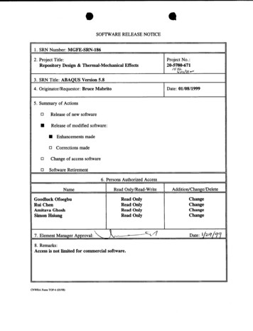
ME 455/555 Intro to Finite Element AnalysisFall 2012Abaqus/CAE truss tutorial25. To change the displayed output, either:a. Change the field output using the tool baroption shortcutb. Use the menu bari. Click on ResultsÎFieldOutputii. Select “U - Spatialdisplacement at nodes”iii. Component U2iv. Click “OK” 2012 Hormoz Zareh20Portland State University, Mechanical Engineering
ME 455/555 Intro to Finite Element AnalysisFall 2012Abaqus/CAE truss tutorial26. To create a text file containing the stresses, verticaldisplacements, and reaction forces (including the total), in themenu bar click on ReportÎField Outputa. For the output variable select (Von) Misesb. On the Setup tab specify the name and the location forthe text filec. Uncheck the “Column totals” optiond. Click “Apply”e. Back on the Variable tab change the position to “Unique Nodal”f. Uncheck the stress variable, and select the U2 spatial displacementg. Click “Apply” 2012 Hormoz Zareh21Portland State University, Mechanical Engineering
ME 455/555 Intro to Finite Element AnalysisFall 2012Abaqus/CAE truss tutorialh. On the Variable tab, uncheck Spatial displacement and select the RF2 reaction forcei. On the Setup tab, check the “Column totals” optionj. Click “OK” 2012 Hormoz Zareh22Portland State University, Mechanical Engineering
ME 455/555 Intro to Finite Element AnalysisFall 2012Abaqus/CAE truss tutorial27. Open the .rpt file with any text editor (such as Notepad)a. One thing to check is that the total downward reaction force is equal to the applied load(1,000 N)b. Each time “Apply” is pressed the .rpt file is updated as long as the “Append to file” option ischecked under “Setup” 2012 Hormoz Zareh23Portland State University, Mechanical Engineering
WARNING: There are no predefined system of units within Abaqus, so the user is responsible for ensuring that the correct values are specified d. Click "OK" ME 455/555 Intro to Finite Element Analysis Fall 2012 Abaqus/CAE truss tutorial 2012 Hormoz Zareh 5 Portland State University, Mechanical Engineering 6. Double click on the "Sections .