Transcription
www.ijcrt.org 2020 IJCRT Volume 8, Issue 7 July 2020 ISSN: 2320-2882FINITE ELEMENT MODELING OF RCC BEAM BYUSING ABAQUST.S.Vishnu Kumar1, N.Rushwanth Chowdary11. Academic Consultant, Dept. of Civil Engineering, SV University College of Engineering, Tirupati.ABSTRACTRCC (Reinforced Cement Concrete) is one of the widely used materials in the construction sector in India. It isnecessary to understand the behavior of RCC member to check the stability aspect of the structure. Therefore, thedevelopment of a finite element model (FEM) may need intensive material testing to incorporate into the materialmodel in any of the finite element (FE) packages available (Sinaei et al., 2011). There are quite a large number ofnumerical material models available in the literature with the potential to develop complete stress-strain curves ofconcrete for compression and tension separately based on the experimental results. In this research, the ABAQUSprogram Hibbitt et al. (1988) is used to model the behavior of RCC beams.Keywords: - ABAQUS, RCC Beam, FEMI. INTRODUCTIONReinforced concrete is a complicated material to be modelled within finite element packages. A proper materialmodel in the finite element model should inevitably be capable of representing both the elastic and plastic behaviour ofconcrete in compression and tension. The complete compressive behaviour should include both elastic and inelasticbehaviour of concrete including strain softening regimes. The simulation of proper behaviour under tension shouldinclude tension softening, tension stiffening and local bond effects in reinforced concrete elements. The finite elementmodel uses the concrete damaged plasticity approach; this model can help to confirm the theoretical calculations aswell as to provide a valuable supplement to the laboratory investigations of behaviour. For validation, a reinforcedconcrete beam was modelled which had been experimentally tested and reported by Kachlakevetal. (2001).The primary concern about the structural failure under anticipated extreme loadings had beenaddressed with the many provisions attributed to issues like: (i) attaining member level/structure level resistanceagainst the code prescribed loads and load combinations(ii) defining all anticipated loads including extremeenvironmental loads. (iii) Attaining structuralIJCRT2007005International Journal of Creative Research Thoughts (IJCRT) www.ijcrt.org25
www.ijcrt.org 2020 IJCRT Volume 8, Issue 7 July 2020 ISSN: 2320-2882integrity and ductility. (iv) providing continuity for connections and (v) providing some general statements aboutresiliency, redundancy and robustness, etc. Therefore, code-compliant buildings highlight the significance of moreinvestigative study related to impact loading issues. It is recognized that experimental observations are muchmore expensive comparative to its counterpart investigations implementing computer analyses. In that sense,finite element (FE) analysis can be an option. Thus, a 3D FE analysis model using ABAQUS was triggered toexplicitly explore the dynamic behavior of a reinforced concrete (RC) structural element. ABAQUS is a verycomplex FE analysis program introduced with huge material characteristics and parameters to reproduce highaccuracy in calculations. But there are no clues to assign exact values for those parameters. Thus, model choosingbased on influential material characteristics and behavioral parameters is an important part of FE analysis beforeinvestigating the actual behavior of a structural element. In this study, thirty analyses have been executed changingdifferent parameters, such as damping, tension and compression stiffness recovery, damage parameter-strain/displacement relations and friction coefficient to choose the best performing FE model. The results of few analyses areto be discussed in this paper. Upon extensive examination of the calculated structural responses of the FE modelscomparing with the published experimental results. This study reveals that FE analysis using proposed model can beapplied to explore dynamic behavior of structural elements subjected to impact vibrationsII.LITERATURE REVIEWDuthinh and starnes, (2001) conducted experiment on strengthening of reinforced concrete beams using carbonfiber reinforced polymer. The seven test beams were cast and strengthening externally with carbon fiber reinforcedpolymer (FRP) laminated after the concrete had cracked were tested under four point bending. The results obtainedfrom this experiment were that CFRP is very effective for flexural strengthening. As the amount of steel reinforcementincreases, the additional strength provided by carbon FRP external reinforcement decreases.The same FRPreinforcement more than doubled the strength of a lightly reinforced beam. Compared to a beam reinforced heavilywith steel only, the beams reinforced with both steel and carbon have adequate deformation capacity, in spite of theirbrittle mode of failure.In the present model, a solid foundation was used, which is more realistic although this modelling requires muchmore memory for the resolution. The solid foundation is more realistic than the liquid foundation, because thedeflection in any nodal point depends not only on the force in this node but also of the forces in all the other nodes.Moreover, all the analytical solutions of the 2D models are based on the proposal that the slab and the foundation are inperfect contact (Coquand, 1989). With the advantages of calculations of the numerical methods by computers, thedeveloped analyses are based on a partial contact between the layers (Huang, 2004). This work includes, mainly, a 3Dmodelling by the use of the computer code of the finite elements "Abaqus 6.7" in order to understand, with moreprecision, the distribution and the evolution of the stresses and displacements in the entire RCC slab. These resultswere shown especially for many loading position, in top and bottom fibres and in the interface with the sub-base. In thenumerical 3D modeling by finite elements using Abaqus 6.7, the authors choose various options of manual andIJCRT2007005International Journal of Creative Research Thoughts (IJCRT) www.ijcrt.org26
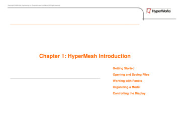
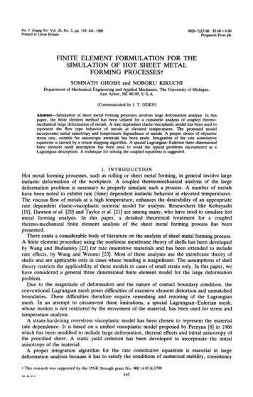
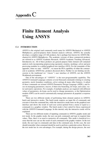
www.ijcrt.org 2020 IJCRT Volume 8, Issue 7 July 2020 ISSN: 2320-2882automatic incrementing with an automatic tolerance of convergence. The control parameters of the management of thenumerical analysis of the problem are adjusted automatically with a low manual adjustment. The convergence criteriaare also adjusted during the analysis to ensure a precise solution. In this numerical approach, two RCC slab separatedby a joint, were modelled. Both rest on a gravel sub-base suitably compacted. The whole also rests on a groundsupport. The geometries and the mechanical properties of material were introduced. These introduced parameters were:the elastic modulus E, the Poisson's ratio n and the admissible stresses of tensile and compression. All dimensionsare finite in 3D; the diagrams of the model are presented.III. DESCRIPTION OF THE SPECIMENThe theoretical Finite Element Analysis, the computation of membrane stresses and deflections correspondingto the applied loads on RCC Beam will be carried out using the standard program (ABAQUS Version 6.10).DIMENSION OF THE SECTIONLength - 2.0mWidth - 0.35mDepth - 0.45mSquare mesh 2mm diameterMain Steel bars 8mm diameter& Stirrups 6mm diameter.Clear cover – 25mmEXECUTION OF PROGRAMThe analysis and the computation of RCC Beam are done using standard program, by executing in thefollowing steps. Two models are created for RCC Beam in ABAQUS. First created the concrete model. Steel model created by used co-ordinates and by used wire option to connected each node by node. A material property is assigned as elastic properties. Section is assigned as homogenous. Mesh and steel model are assigned as solid model. Assembled the two models by used constrains into TIE optionIJCRT2007005International Journal of Creative Research Thoughts (IJCRT) www.ijcrt.org27
www.ijcrt.org 2020 IJCRT Volume 8, Issue 7 July 2020 ISSN: 2320-2882 Job was input Linear analysis was done. Deflection and stress contour is noted.AUTOCAD MODEL FOR RCC BEAM Figure 1. AUTOCADD model of RCC BeamIJCRT2007005International Journal of Creative Research Thoughts (IJCRT) www.ijcrt.org28
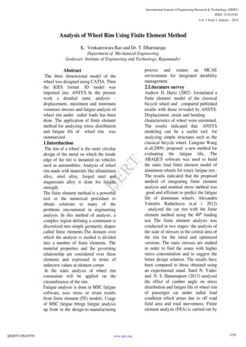
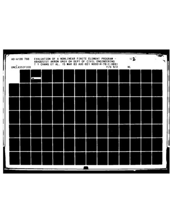
www.ijcrt.org 2020 IJCRT Volume 8, Issue 7 July 2020 ISSN: 2320-2882IV. SIMULATIONSFigure 2. Concrete model in ABAQUSFigure 3. Steel model in ABAQUS.IJCRT2007005International Journal of Creative Research Thoughts (IJCRT) www.ijcrt.org29
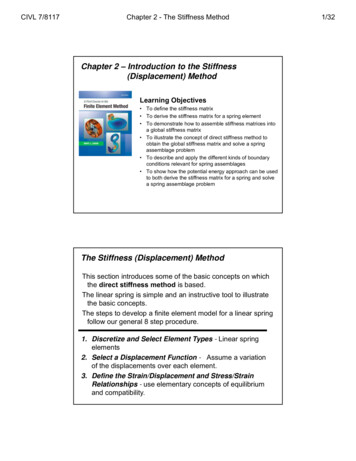
www.ijcrt.org 2020 IJCRT Volume 8, Issue 7 July 2020 ISSN: 2320-2882Figure 4. Assembled model for RCC BeamMATERIAL PROPERTIESThe material properties are taken from IS 456:2000Elastic modulus of concrete 5000 fck 5000 25 25000 N/mm2Table 1. Young’s modulus and Poisson’s ratio for mesh, steel and mortar.S.noMaterial’sYoung’s modulus EPoisson’s ratio ʋ1Cement concrete25 Gpa0.22Square mesh200 Gpa0.33Steel200 Gpa0.3The analysis for the RCC Beam is done in ABAQUS by FEM meshing tool. FEM meshing is done by quadrilateralmesh. Boundary condition is assigned as fixed condition. Concentrated load is applied on the specimen. Job was input.Linear analysis was done.IJCRT2007005International Journal of Creative Research Thoughts (IJCRT) www.ijcrt.org30
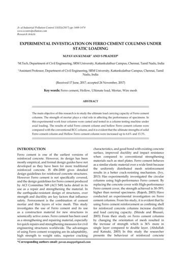
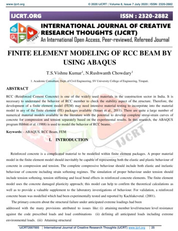
www.ijcrt.org 2020 IJCRT Volume 8, Issue 7 July 2020 ISSN: 2320-2882V. RESULTSPOINT LOAD AND CORRESPONDING RESULTSS.NoLoad in kNDeflection in 530Load 9Deflection (mm)Graph 1. Load vs. DeflectionIJCRT2007005International Journal of Creative Research Thoughts (IJCRT) www.ijcrt.org31
www.ijcrt.org 2020 IJCRT Volume 8, Issue 7 July 2020 ISSN: 2320-2882Figure 5. simply supported beam with point loadThe discretization is done for the clear representation of the contour. Stress contour and deflection are showncomparing the top to bottom sidesFigure 6. Maximum principal stressIJCRT2007005International Journal of Creative Research Thoughts (IJCRT) www.ijcrt.org32
www.ijcrt.org 2020 IJCRT Volume 8, Issue 7 July 2020 ISSN: 2320-2882Figure 7. Minimum principal stressFigure 8. Average principal stressIJCRT2007005International Journal of Creative Research Thoughts (IJCRT) www.ijcrt.org33
www.ijcrt.org 2020 IJCRT Volume 8, Issue 7 July 2020 ISSN: 2320-2882Figure 9. DeformationFigure 10. Deformation 1IJCRT2007005International Journal of Creative Research Thoughts (IJCRT) www.ijcrt.org34
www.ijcrt.org 2020 IJCRT Volume 8, Issue 7 July 2020 ISSN: 2320-2882Figure 11. Deformation 2Figure 12. Deformation 3IJCRT2007005International Journal of Creative Research Thoughts (IJCRT) www.ijcrt.org35
www.ijcrt.org 2020 IJCRT Volume 8, Issue 7 July 2020 ISSN: 2320-2882UNIFORMLY DISTRIUTED LOAD AND CORRESPONDING RESULTSS.NoLoad in kNDeflection in Load vs. Deflection353030Load 9.09411.13Deflection (mm)Graph 2. Load vs. DeflectionIJCRT2007005International Journal of Creative Research Thoughts (IJCRT) www.ijcrt.org36
www.ijcrt.org 2020 IJCRT Volume 8, Issue 7 July 2020 ISSN: 2320-2882Figure 13. Simply supported beam with UDLFigure 14. Maximum principal stressIJCRT2007005International Journal of Creative Research Thoughts (IJCRT) www.ijcrt.org37
www.ijcrt.org 2020 IJCRT Volume 8, Issue 7 July 2020 ISSN: 2320-2882Figure 15. Minimum principal stressFigure 16. Deformation 1IJCRT2007005International Journal of Creative Research Thoughts (IJCRT) www.ijcrt.org38
www.ijcrt.org 2020 IJCRT Volume 8, Issue 7 July 2020 ISSN: 2320-2882Figure 17. Deformation 2Figure 18. Deformation 3VI. CONCLUDING REMARKS ABAQUS has many modeling characteristics with which to model reinforced concrete. ABAQUS can to do the following: model concrete and steel with beam and shell element simulate their interaction apply loads Calculate accurate results and predict behavior not generally obtained through experimentation. The accuracy of the model was validated, and the limitations of matching finite elementmodels to experimental tests held under conditions that are less than ideal was illustrated. The development of a finite element model of an entire bridge illustrates not only the capabilityofABAQUS to represent the behavior of a realistic structure but also the specific capability of the model to predictdeflections, strains, and stresses while minimizing unnecessary complexities.IJCRT2007005International Journal of Creative Research Thoughts (IJCRT) www.ijcrt.org39
www.ijcrt.org 2020 IJCRT Volume 8, Issue 7 July 2020 ISSN: 2320-2882VII. REFERENCES1. ABAQUS, (2004), Example problems manual, Version 6.4.1, HibbittKarlsson&Sorensen, Inc., USA.2. ABAQUS/CAE, (2004), User’s Manuals, Version 6.4.1, HibbittKarlsson& Sorensen,Inc., USA.3. ABAQUS/Explicit, (2004), Theory Manual, Version 6.4.1, HibbittKarlsson&Sorensen, Inc., USA.4. ACI 318-02/318R-02, (2002), Building Code Requirements for Structural Concreteand Commentary, American Concrete Institute, Farmington Hills, MI.5. ASCE 7-02, (2002), Minimum Design Loads for Buildings and Other Structures,American Society of Civil Engineers, Reston, VA.6. Hakuno, M., and Meguro, K., (1993), Simulation of Concrete-Frame Collapse Due toDynamic Loading, Journal of engineering mechanics, 119(9), pp1709-1723.7. Kishi, N., (2004), Practical Methods for Impact Test and Analysis, StructuralEngineering Series, JSCE, impact problems, No.15 (in Japanese).8. Leyendecker, E. V., and Burnett, E. F. P., (1976), the Incidence of AbnormalLoading in residential Buildings, National Bureau of Standards, NBS 98, and Washington, D.C.9. Leyendecker, E. V., and Ellingwood, B. R., (1977), Design Methods for Reducing theRiskof Progressive Collapsein Buildings, National Bureau of Standards, NBS 98,and Washington, D.C.10. Luccioni, B. M., Ambrosini, R. D., andDanesi, R. F., (2004), Analysis of buildingCollapse under blast loads, Journal of engineering structures, ASCE, 26, pp 63-71.11. A.R.Santhakumar, concrete technology, oxford university press, 2007.12. Alfaiate, J., Pires, E.B., & Martins, J.A.C. (1997). A Finite Element Analysis of NonPrescribed Crack Propagation in Concrete. Computers & Structures, 63(1): 17-26.13. Ashour, A.F., & Morley, C.T. (1993). Three-dimensional Nonlinear Finite ElementModeling ofReinforced Concrete Structures. Finite Elements in Analysis and Design, 15:4355.14. Azizinamini, A. (1994). OldConcrete Slab Bridges: Analysis. ASCE Journal of Structural Engineering, 120(1): 3305-3319.15. Barzegar, F. (1994). Generating Reinforcement in FE Modeling of Concrete StructuresASCEJournal of Structural Engineering, 120(5): 1656-62.IJCRT2007005International Journal of Creative Research Thoughts (IJCRT) www.ijcrt.org40
concrete for compression and tension separately based on the experimental results. In this research, the ABAQUS program Hibbitt et al. (1988) is used to model the behavior of RCC beams. Keywords: - ABAQUS, RCC Beam, FEM I. INTRODUCTION Reinforced concrete is a complicated material to be modelled within finite element packages. A proper material