Transcription
Abaqus TutorialsPrepared by:David G. TaggartDepartment of Mechanical, Industrial and Systems EngineeringUniversity of Rhode IslandKingston, RI 02881Prepared for:MCE 466 - Introduction to Finite Element MethodsSpring 2015Copyright 2015, University of Rhode Island, All Rights Reserved.
TABLE OF CONTENTS1. 2D Truss Analysis. 22. Beam Bending Analysis . 53. Plane Stress Analysis . 104. Axisymmetric Analysis . 165. 3D Stress Analysis . 206. Plate Bending Analysis . 247. Column Buckling Analysis. 261
Tutorial 1. 2D Truss AnalysisProblem: Determine the nodal displacements and element stresses for the truss shown below(ref. “A First Course in the Finite Element Method, 5th edition, Daryl L. Logan, 2012,example 3.5, pp. 92-95). Use E 30x106 psi and A 2 in2. Compare to text solution: u1 0.414e-2 in, v1 -1.59e-2 in, element stresses -1035, 1471, and 3965 psi.Start All Programs Abaqus 6.X Abaqus CAE Create Model Database WithStandard/Explicit ModelFile Set Working Directory Browse to find desired directory OKFile Save As save truss tutorial.cae file in Work DirectoryModule: SketchSketch Create Name: truss-demo ContinueAdd Point enter coordinates (0,0), (120,0), (120,120), (0,120) select 'red X'View Auto-FitAdd Line Connected Line select (0,0) node with mouse, then (120,0) node, right click Cancel ProcedureAdd Line Connected Line select (0,0) node with mouse, then (120,120) node, rightclick Cancel ProcedureAdd Line Connected Line select (0,0) node with mouse, then (0,120) node, right click Cancel Procedure DoneModule: PartPart Create select 2D Planar, Deformable, Wire ContinueAdd Sketch select 'truss demo' Done DoneModule: PropertyMaterial Create Name: Material-1, Mechanical, Elasticity, Elastic set Young'smodulus 30e6, Poisson's ratio 0.3 OKSection Create Name: Section-1, Beam, Truss Continue set Material: Material-1,Cross-sectional area: 22
Assign Section select all elements by dragging mouse Done Section-1 OK DoneModule: AssemblyInstance Create Create instances from: Parts Part-1 Dependent (mesh on part) OKModule: StepStep Create Name: Step-1, Initial, Static, General Continue accept default settings OKModule: LoadLoad Create Name: Load-1, Step: Step-1, Mechanical, Concentrated Force Continue select node at (0,0) Done set CF2: -10000 OKBC Create Name: BC-1, Step: Step-1, Mechanical, Displacement/Rotation Continue select nodes at (120,0), (120,120) and (0,120) using SHIFT key to select multiplenodes Done set U1: 0 and U2: 0Module: MeshSet Model: Model-1, Object Part: Part-1Seed Edges select entire truss by dragging mouse Done Method: By number, Bias:None, Sizing Controls, Number of Elements: 1 press Enter DoneMesh Element Type select entire truss by dragging mouse Done Element Library:Standard, Geometric Order: Linear: Family: Truss OK DoneMesh Part OK to mesh the part Instance: YesModule: JobJob Create Name: Job-1, Model: Model-1 Continue Job Type: Full analysis, RunMode: Background, Submit Time: Immediately OKJob Submit Job-1Job Manager Results (transfers to Visualization Module)Module: VisualizationViewport Viewport Annotation Options Legend Text Set Font Size 14, Applyto: Legend, Title Block and State Block OK OKView Graphics Options Viewport Background Solid Color White (click on blacktile to change background color)Options Common Labels select 'Show element labels: Black' and 'Show node labels:Red’ OKPlot Undeformed ShapePlot Deformed ShapePlot Contours On Deformed ShapeResult Options unselect “Average element output at nodes”Result Field Output Component: S11 OKCtrl-C Copies graphics window to clipboard Paste in MS Word, etc.3
Report Field Output Variable Position: Unique Nodal select U: SpatialDisplacements Apply Unselect UReport Field Output Variable Position: Centroid select S: Stress Components Click on ‘ ’ and unselect all stresses except S11 Apply CancelOpen file ‘Abaqus.rpt’ and cut and paste desired results into MS WordFile Save enter desired file name (Abaqus will append .cae)File ExitResults:Deformed Mesh:Tabulated Results (using cut and paste from Abaqus.rpt)4
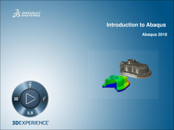
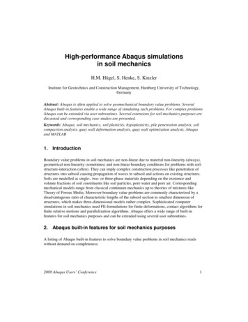
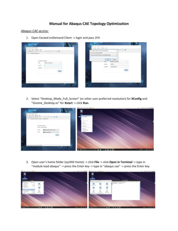
Tutorial 2. Beam Bending AnalysisConsider the beam bending problem:Assume that the beam is made of steel (E 30x106 psi, G 11.5x10⁶ psi) and has a 2" deep x 5"high rectangular cross section (Iz (2)(53)/12 20.83 in4, Iy (5)(23)/12 3.333 in4). Determine themaximum deflection and stress in the bar and the using 8 beam elements. Compare the solutionto the beam theory solution.Beam theory solutionBeam theory gives the following displacement solution:Pbx 2wxx b 2 L2 2 Lx 2 x 3 L3 , 0 x a6 EIL24 EIPa ( L x) 2wx v( x)x a2 2L x 2 Lx 2 x 3 L3 , a x L6 EIL24 EI v( x)()(())()where v(x) is the displacement, P is the concentrated force (-5000 lb), x is the distance from theleft end of the beam, EI is the flexural stiffness of the beam, wo is the uniform distributed load(-50 lb/ft -4.167 lb/in), a 15 ft and b 5 ft. The displacement field and bending stressdistribution predicted by beam theory are shown below. Note that the maximum deflection,approximately -1.89 in, occurs between x 11 ft and x 12 ft and the maximum bending stress isapproximately 29,700 psi at x 15 ft.5
403x 10-0.22.5-0.4Bending stress (psi)Displacement (in)-0.6-0.8-1-1.2-1.4-1.621.510.5-1.8-20246810x (ft)121416182000246810x (ft)1214161820Finite Element solutionStart All Programs Abaqus 6.X Abaqus CAE Create Model Database WithStandard/Explicit ModelFile Set Working Directory Browse to find desired directory OKFile Save As save beam tutorial.cae file in Work DirectoryModule: SketchSketch Create continueAdd Point select 'red X'Add Line Connected Line enter coordinates (0,0), (180,0), (240,0), right click Cancel Procedure DoneModule: PartPart Create select 2D Planar, Deformable, Wire, Approx size 200 ContinueAdd Sketch select 'Sketch-1' Done DoneModule: PropertyMaterial Create Name: Material-1, Mechanical, Elasticity, Elastic set Young'smodulus 30e6, Poisson's ratio 0.3 OKProfile Create Generalized A 10, I1 20.83, I12 0, I2 3.333, J 0 OKSection Create Name: Section-1, Beam, Beam Continue Section Integration –Before Analysis Profile Name: Profile-1 Linear Properties E 30e6,G 11.54e6 Output Points enter (x1, x2) (0,-2.5) and (x1, x2) (0,2.5) OKAssign Section select all elements by dragging mouse Done Section-1 Done OKAssign Beam Section Orientation select full model Done n1 direction 0.0,0.0,-1.0 OK DoneModule: AssemblyInstance Create Create instances from: Parts Part-1 Dependent (mesh on part) OK6
Module: StepStep Create Name: Step-1, Initial, Static, General Continue accept default settings OKModule: LoadLoad Create Name: Load-1, Step: Step 1, Mechanical, Line Load Continue selectfull model Done set Component 1 0, Component 2 -4.167 OKLoad Create Name: Step-1, Step: Step 1, Mechanical, Concentrated Force Continue select point at (180,0) Done set CF2 -5000 OKBC Create Name: BC-1, Step: Step-1, Mechanical, Displacement/Rotation Continue select point at (0,0) Done U2 0 OKBC Create Name: BC-1, Step: Step-1, Mechanical, Displacement/Rotation Continue select point at (240,0) Done U1 U2 0 OKModule: MeshSet Model: Model-1, Object Part: Part-1Seed Edges select entire beam by dragging mouse Done Method: By size, Bias:None, Sizing Controls, Element Size 30 OK DoneMesh Element Type select entire truss by dragging mouse Done Element Library:Standard, Geometric Order: Linear: Family: Beam, Cubic interpolation (B23) OK DoneMesh Part OK to mesh the part Instance: YesModule: JobJob Create Name: Job-1, Model: Model-1 Continue Job Type: Full analysis, RunMode: Background, Submit Time: Immediately OKJob Manager Submit Job-1Job Manager Results (transfers to Visualization Module)Module: VisualizationViewport Viewport Annotation Options Legend Text Set Font Size 14, Applyto: Legend, Title Block and State Block OK OKView Graphics Options Viewport Background Solid Color White (click on blacktile to change background color)Options Common Labels select 'Show element labels: Black' and 'Show node labels:Red’ OKPlot Deformed ShapeCtrl-C to copy viewport to clipboard Open MS Word Document Ctrl-V to paste imageResult Field Output select S, Component: S11 Section Points Top and Bottom OKPlot Contours On Deformed ShapeReport Field Output Variable Position: Unique Nodal select Spatial displacement:U2: Spatial Displacements, Rotational displacement: UR3 OKReport Field Output Variable Position: Unique Nodal select Stress components:S11, Section points - All OKCut and paste tabulated results from 'Abaqus.rpt' file to MS Word document.7
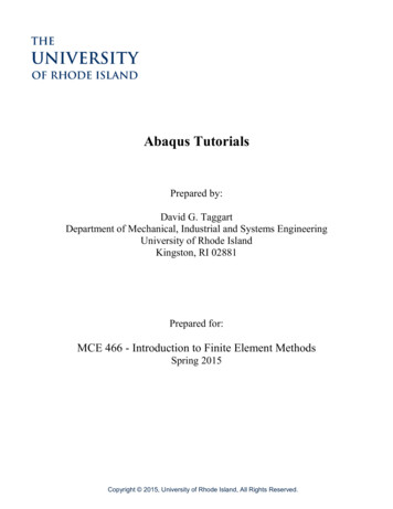
Results:Deformed MeshBending Stress Contours8
Tabulated Output:NodeS.S11Label@Loc 1--------------------------------137.5090229.7425E 03337.508546.11361E 03511.7396E 03616.9155E 03721.6413E 03825.9169E 03915.1150E 03MinimumNodeU.U2Label@Loc -1.872328-1.841949-840.968E-03At Node37.50853MinimumAt Node29.7425E 032MaximumTotal127.259E 03MaximumNodeS.S11Label@Loc 5E 033-37.50854-6.11361E 035-11.7396E 036-16.9155E 037-21.6413E 038-25.9169E 039-15.1150E 03Minimum-1.872327At Node-1.68753E-331Total-9.55695NodeUR3Label@Loc .3119E-037-3.60058E-0385.91106E-03926.0144E-03At Node-29.7425E 032MinimumAt Node-37.50853MaximumTotal-127.259E 03MaximumAt NodeAt Node-21.8438E-031At Node29.0450E-033Total3.60058E-039
Tutorial 3. Plane Stress AnalysisConsider the problem of a 4” x 2” x 0.1” aluminum plate (E 10e6 psi, ν 0.3) with a 1” diametercircular hole subjected to an axial stress of 100 psi.Use of SymmetryFull ModelUX 0UY 0Determine the maximum axial stress associated with the stress concentration at the edge of thecircular hole. Compare this solution with the design chart (ref. “Shigley's MechanicalEngineering Design,” 10th Edition, Budynas and Nisbett, 2015) for the case d/w 0.5 which givesσmax 2.18 (200 psi) 436 psi.10
Finite Element solutionStart All Programs Abaqus 6.X Abaqus CAE Create Model Database WithStandard/Explicit ModelFile Set Working Directory Browse to find desired directory OKFile Save As save plane stress tutorial.cae file in Work DirectoryModule: SketchSketch Create Approx size - 5Add Point enter coordinates (.5,0), (1,0), (1,2), (0,2), (0,.5) select 'red X'View Auto-FitAdd Line Connected Lines select point at (.5,0) with mouse, then (1,0), (1,2), (0,2),(0,.5) right click Cancel Procedure DoneAdd Arc Center/Endpoint select point at (0,0), then (.5,0), then (0,.5) right click Cancel Procedure DoneModule: PartPart Create select 2D Planar, Deformable, Shell, Approx size - 5 ContinueAdd Sketch select 'Sketch-1' Done DoneModule: PropertyMaterial Create Name: Material-1, Mechanical, Elasticity, Elastic set Young'smodulus 10e6, Poisson's ratio 0.3 OKSection Create Name: Section-1, Solid, Homogeneous Continue Material Material-1, plane stress/strain thickness - 0.1 OKAssign Section select entire part by dragging mouse Done Section-1, Thickness: Fromsection OKModule: AssemblyInstance Create Create instances from: Parts Part-1 Dependent (mesh on part) OKModule: StepStep Create Name: Step-1, Initial, Static, General Continue accept default settings OKModule: LoadLoad Create Name: Load-1, Step: Step 1, Mechanical, Pressure Continue select topedge Done set Magnitude -100 OKBC Create Name: BC-1, Step: Step-1, Mechanical, Displacement/Rotation Continue select bottom edge Done U2 0BC Create Name: BC-2, Step: Step-1, Mechanical, Displacement/Rotation Continue select left edge Done U1 0Module: MeshSet Model: Model-1, Object Part: Part-111
Seed Edges select full model by dragging mouse Done Method: By size, Bias:None, Sizing Controls, Element Size 0.1 OK DoneMesh Controls Element Shape Tri (for triangles), Quad (for quadrilaterals), or Quaddominated (for mixed triangles and quads - mostly quads), Technique: Free OKMesh Element Type select full model by dragging mouse Done Element Library:Standard, Geometric Order: Linear, Family: Plane Stress Linear/Tri (for CST),Quadratic/Tri (for LST), Linear/Quad (for 4 node quad), or Quadratic/Quad (for 8-nodequad) OK Done (try varying element type, interpolation functions and meshdensity)To refine mesh locally:Seed Edges Select bottom edge and arc (use Shift Key to select multiple edges) Done Method: By size, Bias: Single, Minimum size: .02, Maximum Size: 1, Flip Bias:Select and click on edges such that arrow points toward desired refined point OK DoneMesh Part OK to mesh the Part: Yes DoneTools Query Region Mesh Apply (displays number of nodes and elements at bottom ofscreen)Module: JobJob Create Name: Job-1, Model: Model-1 Continue Job Type: Full analysis, RunMode: Background, Submit Time: Immediately OKJob Manager Submit Job-1Job Manager Results (transfers to Visualization Module)Module: VisualizationViewport Viewport Annotation Options Legend Text Set Font Size 14, Applyto: Legend, Title Block and State Block OK OKView Graphics Options Viewport Background Solid Color White (click on blacktile to change background color)Plot Deformed ShapeDeformed Shape Options Basic Show superimposed undeformed plot OKCtrl-C to copy viewport to clipboard Open MS Word Document Ctrl-V to paste imageResult Options Unselect “Average element output at nodes” OKResult Field Output Name - S Component S22 OKPlot Contours On Deformed ShapeCtrl-C to copy viewport to clipboard Open MS Word Document Ctrl-V to paste imageTools Query Probe Values select desired Field Output (click on Field output variableicon) and select desired component (S11, S22, etc.) OK Probe Nodes movecursor to desired location to view nodal resultsTools Path Create Node List Continue Add Before select nodes alongbottom edge Done OKTools XY Data Create Source: Path Continue X Distance PlotCtrl-C to copy viewport to clipboard Open MS Word Document Ctrl-V to paste imageReport Field Output Position - Centroid Variable – Mises, S11, S22, S12 ApplyExamine tabulated results in 'Abaqus.rpt' file.12
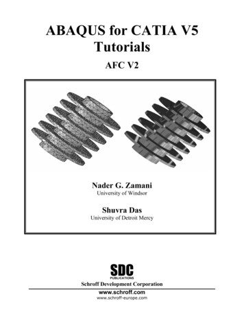
Typical Results (no edge bias)CST - 3 node triangle (linear interpolation)LST - 6 node triangle (quadratic interpolation)4-node Quad (linear interpolation)8-node Quad (quadratic interpolation)13
Typical Results (with edge bias)CST - 3 node triangle (linear interpolation)LST - 6 node triangle (quadratic interpolation)4-node Quad (linear interpolation8-node Quad (Quadratic interpolation)14
Stress Distribution along y 0 (bottom edge of mesh)15
Tutorial 4. Axisymmetric AnalysisConsider a steel (E 200 GPa, ν 0.3) cylindrical pressure vessel with hemispherical end caps asshown below. The pressure vessel has an inner radius of R 0.5 m and a wall thickness of t 0.05 m. An internal pressure of 100 MPa is applied.Theoretical SolutionFor pressure vessels with R/t 20, thin walled theory gives side wall stresses:σ rr 0pR 1000 MPatpRσ zz 500 MPa2tσ VM 866 MPaσ θθ and end cap stressesσ rr 0pR 500 MPatσ VM 500 MPaσ θθ σ φφ 16
Finite Element solutionStart All Programs Abaqus 6.X Abaqus CAE Create Model Database WithStandard/Explicit ModelFile Set Working Directory Browse to find desired directory OKFile Save As save axisymmetric tutorial.cae file in Work DirectoryModule: Sketch(Note: reorient geometry such that positive z-axis is vertical upward and positive r-axis ishorizontal to the right)Sketch Create Approx size - 5Add Point enter coordinates (.5,0), (.55,0), (.5,.5), (.55,.5), (0,1.0), (0,1.05) select 'redX'View Auto-FitAdd Line Connected Line select point at (.5,5) with mouse, then (.5,0), (.55,0), (.55,.5) right click Cancel Procedure DoneAdd Line Connected Line select point at (0,1.0) with mouse, then (0,1.05) rightclick Cancel Procedure DoneAdd Arc Center/Endpoint select point at (0,.5), then (.5,.5), then (0,1.0) CancelProcedure DoneAdd Arc Center/Endpoint select point at (0,.5), then (.55,0), then (0,1.05) CancelProcedure DoneModule: PartPart Create select Axisymmetric, Deformable, Shell, Approx size - 5 ContinueAdd Sketch select 'Sketch-1' Done DoneModule: PropertyMaterial Create Name: Material-1, Mechanical, Elasticity, Elastic set Young'smodulus 200e9, Poisson's ratio 0.3 OKSection Create Name: Section-1, Solid, Homogeneous Continue Material Material-1, plane stress/strain thickness – leave unselected OKAssign Section select entire part by dragging mouse Done Section-1 OKModule: AssemblyInstance Create Create instances from: Parts Part-1 Dependent (mesh on part) OKModule: StepStep Create Name: Step-1, Initial, Static, General Continue accept default settings OKModule: LoadLoad Create Name: Load-1, Step: Step 1, Mechanical, Pressure Continue selectinterior edges (use shift key to select multiple edges) Done set Magnitude 100e6 OK17
BC Create Name: BC-1, Step: Step-1, Mechanical, Symmetry/Antisymmetry/Encastre Continue select bottom edge (z 0) Done YSYM (U2 UR1 UR2 0)BC Create Name: BC-2, Step: Step-1, Mechanical, Symmetry/Antisymmetry/Encastre Continue select left edge (r 0) Done XSYM (U1 UR2 UR3 0)Module: MeshSet Model: Model-1, Object Part: Part-1To create partition separating side wall from end cap: Tools Partition Type: Face Sketch Add Line Connected Line use mouse to draw line from top left totop right of side wall right click Cancel procedureSeed Edge by Size select full model by dragging mouse Done Element Size 0.02 press Enter DoneMesh Controls select full model Element Shape Quad Structured OKMesh Element Type Axisymmetric Stress Quadratic/Quad (for 8-node quad) OK DoneMesh Instance OK to mesh the part Instance: Yes DoneTools Query Mesh Done (displays number of nodes and elements at bottom of screen)Module: JobJob Create Name: Job-1, Model: Model-1 Continue Job Type: Full analysis, RunMode: Background, Submit Time: Immediately OKJob Manager Submit Job-1Job Manager Results (transfers to Visualization Module)Module: VisualizationViewport Viewport Annotation Options Legend Text Set Font Size 14, Applyto: Legend, Title Block and State Block OK OKView Graphics Options Viewport Background Solid Color White (click on blacktile to change background color)Plot Select Undeformed Shape, Deformed Shape and Allow Multiple Plot StatesOptions Common Deformed Scale Factor Uniform Value: 100Ctrl-C to copy viewport to clipboard Open MS Word Document Ctrl-V to paste imagePlot Contours Result Option Set Nodal Averaging Threshold to 0% ApplyResult Field Output Name , Invariant - Mises OKCtrl-C to copy viewport to clipboard Open MS Word Document Ctrl-V to paste imageTools Query Probe Values Apply select desired Field Output (S, Mises) ProbeNodes move cursor to desired location to view nodal resultsAlong bottom symmetry plane (z 0, .5 r .55), Probe von Mises stress to show variation from827 to 1,007 MPa (as compared to theoretical approximation of 1,000 MPa)Along axis of symmetry edge (1 z 1.05, r 0), Probe von Mises stress to to show variationfrom 455 to 603 MPa (as compared to theoretical approximation of 500 MPa)18
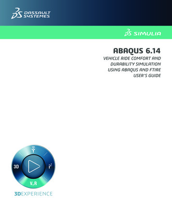
Undeformed and Deformed Shape:Von Mises Stress contours19
Tutorial 5. 3D Stress AnalysisConsider the problem studied previously using plane stress analysis. While nothing is gained byusing a 3D finite element analysis for this problem, it does provide a simple demonstration case.For this demonstration, we will not impose symmetry as we did for the plane stress analysis.Again, this is not ideal modeling practice.The problem to be considered is a 4” x 2” x 0.1” aluminum plate (E 10e6 psi, ν 0.3) with a 1”diameter circular hole subjected to an axial stress of 100 psi. Determine the maximum axialstress associated with the stress concentration at the edge of the circular hole. Compare thissolution with the design chart (ref. Shigley's Mechanical Engineering Design, 10th Edition,Budynas and Nisbett, 2015) for the case d/w 0.5 which gives σmax 2.18 (200 psi) 436 psi.The geometry can be created using Abaqus drawing tools or by importing a part created in aCAD package. For this tutorial, we will demonstrate both creating the part in Abaqus andimporting a part created in Solidworks. In Solidworks, saving the part in either ACIS (.sat) orParasolid (.x t) format works well.2-D Problem3-D Model20
Finite Element solutionStart All Programs Abaqus 6.X Abaqus CAE Create Model Database WithStandard/Explicit ModelFile Set Working Directory Browse to find desired directory OKFile Save As save three D tutorial.cae file in Work DirectoryCreating the geometry in Abaqus:Module: SketchSketch Create Approx size - 50Add Line Rectangle (-1,-2), (1,2) right click Cancel ProcedureView AutoFitAdd Line Circle (0,0), (0,.5) right click Cancel ProcedureDoneModule: PartPart Create select 3D, Deformable, Solid, Extrusion ContinueAdd Sketch select 'Sketch-1' Done Done Extrude depth 0.1Importing the part (created by Solidworks, saved as ACIS .sat):File Import Part select file “plate w hole.sat” OK OKModule: PropertyMaterial Create Name: Material-1, Mechanical, Elasticity, Elastic set Young'smodulus 10e6, Poisson's ratio 0.3 OKSection Create Name: Section-1, Solid, Homogeneous Continue Material Material-1, plane stress/strain thickness – leave unselected OKAssign Section select entire part by dragging mouse Done Section-1 OKModule: AssemblyInstance Create Create instances from: Parts Part-1 Dependent (mesh on part) OKModule: StepStep Create Name: Step-1, Initial, Static, General Continue accept default settings OKModule: LoadLoad Create Name: Load-1, Step: Step 1, Mechanical, Pressure Continue select topface Done set Magnitude -100 OKView Rotate rotate model to expose bottom face red XBC Create Name: BC-1, Step: Step-1, Mechanical, Displacement / Rotation Continue select bottom face Done U2 021
BC Create Name: BC-2, Step: Step-1, Mechanical, Displacement / Rotation Continue select lower left corner of front face (where x -1, y -1, z .1) Done U1 U3 0(this prevents rigid body motion)BC Create Name: BC-3, Step: Step-1, Mechanical, Displacement / Rotation Continue select corner of back face (where x -1, y -1, z 0) Done U1 0 (this preventsrigid body rotation about the y-axis)Module: MeshSeed Edge by Size select entire model Done Element Size 0.1 press Enter DoneMesh Controls Element Shape Hex /Sweep or Tet/FreeMesh Element Type 3D Stress Hex/Linear/Reduced Integration unselected, Hex/Quadratic/Reduced Integration unselected, Tet/Linear or Tet/Quadratic OKMesh Instance OK to mesh the part Instance: Yes DoneTools Query Region Mesh Apply (displays number of nodes and elements at bottom ofscreen)Module: JobJob Create Name: Job-1, Model: Model-1 Continue Job Type: Full analysis, RunMode: Background, Submit Time: Immediately OKJob Manager Submit Job-1Job Manager Results (transfers to Visualization Module)Module: VisualizationViewport Viewport Annotation Options Legend Text Set Font Size 14, Applyto: Legend, Title Block and State Block OK OKView Graphics Options Viewport Background Solid Color White (click on blacktile to change background color)Plot Contours On Deformed ShapeResult Option Unselect “Average element output at nodes”Result Field Output Name - S Component S22 OKCtrl-C to copy viewport to clipboard Open MS Word Document Ctrl-V to paste image22
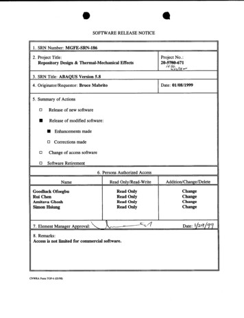
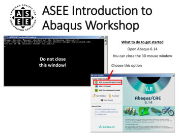
Tet elements – Linear2,025 nodesS22 (max) 445.9 psiTet elements – Quadratic12,234 nodesS22 (max) 458.2 psiQuad elements – Linear1,798 nodesS22 (max) 360.8 psiQuad elements – Quadratic6,141 nodesS22 (max) 438.8 psi23
Tutorial 6. Plate Bending AnalysisConsider a circular aluminum plate (E 10e6 psi, ν 0.3) of radius 10” and thickness 0.2”. Theplate is simply supported around its outer perimeter and is subjected to a transverse pressure of10 psi. Using plate (shell) elements, determine the deflection at the center of the plate. Platetheory gives the plate deflection asPR 4 5 υ w 64 D 1 υ whereEt 3D 12(1 υ 2 )For our case, the predicted deflection is 0.290”.Finite Element solutionStart All Programs Abaqus 6.X Abaqus CAE Create Model Database WithStandard/Explicit ModelFile Set Working Directory Browse to find desired directory OKFile Save As save plate tutorial.cae file in Work DirectoryModule: SketchSketch Create Approx size - 50Add Circle center point (0,0), perimeter point (10,0) right click Cancel Procedure DoneModule: PartPart Create select 3D, Deformable, Shell, Planar ContinueAdd Sketch select 'Sketch-1' Done DoneModule: PropertyMaterial Create Name: Material-1, Mechanical, Elasticity, Elastic set Young'smodulus 10e6, Poisson's ratio 0.3 OKSection Create Name: Section-1, Shell, Homogeneous Continue Shell thickness 0.2 Material - Material-1 OKAssign Section select entire part by dragging mouse Done Section-1 OKModule: AssemblyInstance Create Create instances from: Parts Part-1 Dependent (mesh on part) OKModule: StepStep Create Name: Step-1, Initial, Static, General Continue accept default settings OK24
Module: LoadLoad Create Name: Load-1, Step: Step 1, Mechanical, Pressure Continue select topface Done set Magnitude 10 OKBC Create Name: BC-1, Step: Step-1, Mechanical, Displacement / Rotation Continue select perimeter Done U1 U2 U3 0Module: MeshModel Tree Parts Part-2 double click on MeshSeed Edge by Size select entire model Done Element Size 0.5 press Enter DoneMesh Controls Element Shape QuadMesh Element Type Shell Quadratic OK DoneMesh Instance OK to mesh the part Instance: Yes DoneTools Query Region Mesh Apply (displays number of nodes and elements at bottom ofscreen)Module: JobJob Create Name: Job-1, Model: Model-1 Continue Job Type: Full analysis, RunMode: Background, Submit Time: Immediately OKJob Manager Submit Job-1Job Manager Results (transfers to Visualization Module)Module: VisualizationViewport Viewport Annotation Options Legend Text Set Font Size 14, Applyto: Legend, Title Block and State Block OK OKView Graphics Options Viewport Background Solid Color White (click on blacktile to change background color)Plot Contours Result On Deformed ShapeResult Field Output Name - U Component U3 OKCtrl-C to copy viewport to clipboard Open MS Word Document Ctrl-V to paste image25
Tutorial 7. Column Buckling AnalysisConsider a 5 m column with a 10 cm circular cross-section (R .05m) loaded in axialcompression. The column is pinned at its ends. Determine the critical buckling modes andcorresponding mode shapesTheoretical SolutionThe theoretical Euler buckling loads are given byFor a steel column (E 200 GPa) with I 4.909e-6 m4, the critical buckling loads and modeshapes are given byTable 1. Theoretical Buckling 1.395e7First three mode shapesFinite Element solutionStart All Programs Abaqus 6.X Abaqus CAE Create Model Database WithStandard/Explicit ModelFile Set Working Directory Browse to find desired directory OKFile Save As save buckling tut
Open file 'Abaqus.rpt' and cut and paste desired results into MS Word . File Save enter desired file name (Abaqus will append .cae) File Exit . Results: Deformed Mesh: Tabulated Results (using cut and paste from Abaqus.rpt) 5 Tutorial 2. Beam Bending Analysis .