Transcription
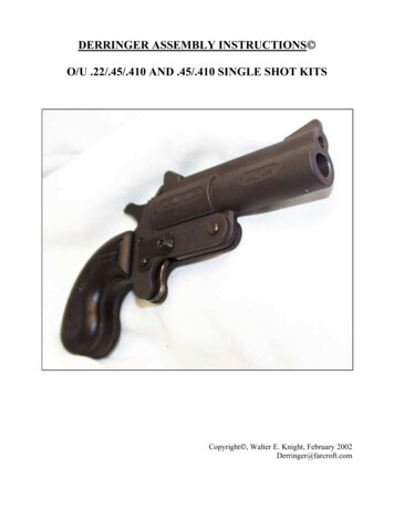
DERRINGER ASSEMBLY INSTRUCTIONS O/U .22/.45/.410 AND .45/.410 SINGLE SHOT KITSCopyright , Walter E. Knight, February 2002Derringer@farcroft.com
INTRODUCTIONThese instructions assume that you have purchased the “Breech Face and Side Plate Kit” as well asthe “Derringer Kit”, neither of which are included with these instructions. These kits may also go bythe names of FMJ or Cobray. While these instructions are specifically designed for the O/UDerringer 22/45/410, they will also work for the 45/410 Derringer with minimal changes. The kitscan be sold separately and shipped without going through a Federal Firearms License (FFL) transferagent because they are separate kits from separate vendors AND separately incomplete.I do not know all the laws or regulations in every location where these derringers may be made orsold. I may not even know the country. It is YOUR responsibility to do the necessary research todetermine the appropriate legal and regulatory guidelines. If you purchased these instructions beforeyou obtained the kits, then do the research BEFORE you buy the kits so that you are not surprisedby limitations, regulations or legal restrictions after you have spent more money; or riskingprosecution and/or incarceration.The actual process of building rather than purchasing the breech face and side plates is beyond thescope of these instructions. You may try www.gunbroker.com, www.ebay.com, orwww.auctionarms.com where such construction diagrams are usually available for sale. Although Ican possibly help you locate appropriate kits, WE DO NOT CARRY OR SELL ANY PARTSOR KITS. If you are not successful obtaining or constructing the parts yourself and you want afully functional firearm, take the kits to your local FFL gunsmith who can help you if it is legal todo so in your location. The gunsmith may and probably will require you to complete the standarddocumentation and background checks required for purchasing a handgun. Be sure you understandthe laws in your location and your abilities to obtain or construct these parts and to possess afunctional finished product BEFORE you purchase and/or complete the kits.Before starting, I recommend that you scan the document for yellow highlighted text that containssome of the tools that may be either required or optional. In some cases, alternatives might work(e.g., a standard hammer may suffice instead of a flat faced hammer, the painting is optional ).The very last page is a duplicate of the diagram and parts list and the highlighted tool list that youcan tear off for reference before and during the assembly process.2
PARTS DIAGRAM1. Open both kits and compare the parts with the inventory list below to be certain that youhave everything you need. One kit contains only parts 17 and 18 while the other kit containsall the others. Another copy of this parts list and diagram is on the last page to be torn off forreference during the assembly process. See the drawing above to assist you in this process.The contents of the kits are as follows:(1) Trigger(2) Trigger Pin(3) Safety Pin(4) Trigger Spring(5) Hammer(6) Hammer Spring(7) Hammer Plunger(8) Barrel(9) Barrel Pin(10) Barrel Latch Knob – 2 ea.(11) Barrel Latch Pin(12) Barrel Pin E Clip(13) Safety Shield(14) Safety E Clip(15) Grip Screw(16) Left Grip, Right Grip & Spacer – 1 ea.(17) Breech Face(18) Side Plate – 2 ea.NOTE: If you can not see this diagram or the diagram on the final page, please email your faxnumber to me at Derringer@farcroft.com and I will fax a copy to you at no cost.3
2. Clear enough space on a non-combustible surface to work. DO NOT LOAD THEDERRINGER OR HAVE ANY AMMUNITION IN THE SAME ROOM AT ANYTIME DURING THE CONSTRUCTION! Consider that at some point you will need tobraze the Breech Face to each of the Side Plates and take appropriate precautions. Removeall combustible materials, keep a bucket of water and a fire extinguisher handy, and be sureto wear safety goggles or a welding helmet as well as welding gloves. Brazing is stronglyrecommended over welding due to the lower but totally adequate temperatures and becauseit is easier and requires less sophisticated equipment. Do NOT solder, Superglue, or Epoxythe breech face to the side plates as the strength of these methods is insufficient given thepressures involved. The actual process of welding and brazing is beyond the scope of theseinstructions; however, detailed instructions were recently available /contents.htm or can be found byusing your browser to search the web for “brazing.”3. Start with the two Side Plates (18). Be certain that both sides of the Breech Face andlocations where the brazing will occur on the flat vertical edges of the Side Plates arecompletely flat. Use a flat file or a rotary tool to remove any burrs. Properly clean anddegrease the areas that will be brazed in a separate well-ventilated area (preferably outside)because the degreasing fumes stink and remain present for quite some time. Insert theSpacer (16) between the Side Plates and the Left and Right Grips (16) on the respectiveoutside of the Side Plates. Attach this with only moderate pressure (recognizing that you willbe removing the Grips and Spacer later in the assembly process) using the Grip Screw (15).This will give you a sense of how far apart the Side Plates will need to be once they arebrazed to the Breech Face.4. Place the Barrel (8) between the Side Plates and insert the Barrel Pin (9) to hold it in place.Do NOT secure it with the Barrel Pin E Clip (12) at this point. The only reason for attachingit is to provide additional assistance in determining the separation of the Side Plates. (HINT:As you proceed, one of the most important factors will be to have the Side Plates absolutelyparallel, perfectly aligned in every direction, and exactly spaced apart for the final assemblyto work. This perfect alignment requirement is the MOST CRUCIAL aspect of the entireassembly.)5. Insert the round part of Safety Pin (3) through the square hole on the left side of theassembly and push it through until the round end protrudes slightly through the right side.The “left,” “right,” “back,” “front” “above” “behind” or “beneath” sidethroughout the instructions is from the perspective of aiming the derringer.The square hole may not be large enough to allow the square part of the Safety Pin to beinserted even when properly aligned with the hole. If this occurs, remove the Safety Pin anduse a small flat file to widen the hole on the Side Plate. Be sure to maintain a square hole bylightly filing EACH of the 4 sides ONCE and then retry inserting the Safety Pin. Continueuntil the square part of the Safety Pin fits snugly through the hole. Do NOT excessively filethe hole on the Side Plate – the fit should be snug so the Safety Pin can be pushed back andforth through both side plates with only significant finger pressure but cannot be completelyremoved by finger pressure from either side. Now repeat this process by inserting the round4
part of Safety Pin (3) through the square hole on the right side of the assembly and push itthrough until the round end protrudes slightly through the left side.Once complete leave the Safety Pin in place with the square part approximately half waythrough the right Side Plate. Starting on the left side of the assembly, insert the small end ofthe Trigger Pin (2) with the recessed notch through the hole just beneath the Safety Pin untilthe small end with the recessed notch protrudes through the right Side Plate and the largerpart of the Trigger Pin is flat against the left Side Plate. Attach the curved part of the SafetyShield (13) through the recessed notch of the protruding section of the Trigger Pin. Turn theSafety Shield counter-clockwise and ensure that the round hole aligns with the oval hole onthe right Side Plate. The purpose here continues to be Side Plate alignment.6. Close the Barrel (8) attached in step 4 by swinging it down upon the Side Plates. The edgesshould make complete contact with both Side Plates. Test this by inserting a piece of paperbetween the Barrel and each of the Side Plates. Pressing down on the Barrel, try to removeeach piece of paper. Alignment is good if the paper either tears or requires considerableforce to remove. If not, open the Barrel, adjust the vertical orientation of the Side Plates, andtry again until you are successful. Once complete, open the Barrel to remove any remainingpieces of paper.7. Insert the Breech Face (17) with the protruding notch down between the rear end of theBarrel and the flat front ends of the Side Plates. The protruding notch on the Breech Faceshould fit tightly between the Side Plates. Push down hard on the Breech Face to ensure thatthe non-protruding bottom edge is COMPLETELY seated on the top of BOTH Side Plates.a. Close the Barrel. The fit between the Breech Face and the Barrel should be veryclose, touching each other or even slightly snug. If it is too tight, push slightlyforward on the Barrel and strongly back on the Breech Face to see if this resolves theproblem. If this does not resolve the problem, remove the Breech Face and use a flatfile on the flat surface to reduce its thickness. Recheck the fit frequently to ensurethat you do not over-file the Breech Face. If it is too loose, push slightly back on theBarrel. A correct fit allows the Barrel to move up and down easily while still beingclose or lightly touching the Breech Face.Do not try the intuitively easier process of filing the flat front ends of the Side Platesrather than the Breech Face unless you have confirmed everything is properlyassembled and the fit is so tight that you can’t even close the Barrel. If the Barrelcannot close, the best solution would be to contact the vendor from whom youpurchased the Side Plates to obtain replacements. If you MUST file the Side Plates(e.g., you made them yourself from a diagram), be extremely careful to retain SidePlate alignment and flatness. Using a perfectly flat file, file the entire vertical side ofone Side Plate and then the entire vertical side of the other Side Plate ONCE andthen recheck the alignment. Proceed until the Barrel can be closed and then revert tothe procedure described in the beginning of this step.b. The fit between the Breech Face and the Side Plates should be VERY tight bothhorizontally and vertically. You will soon braze these parts together. Furthermore,the alignment of the Breech Face should be such that the hole in the Breech Face is5
centered between the Side Plates, and with no part of the protruding notch on theBreech Face visible when observing from either side of the assembly.8. Keeping the Breech Face immobile, open the Barrel. Now comes a tricky part. Hold anappropriately sized and heat resistant vise grip in a vertical position aligned with the SidePlates with the clamp end facing down in one hand. Hold the Breech Face TIGHTLY inplace down and against the back of the Side Plates with the other hand. Adjust the clamp sothat it will hold the three pieces tightly together, release it and then tighten it just a tad more.A proper clamping will result in the Breech Face completely flat and tight against the frontof the Side Plates, the protruding notch on the Breech Face invisible from either side of theassembly, and the non-protruding bottom of the Breech Face completely flat and tightagainst the top of the Side Plates. Validate that the hole in the Breech Face remainedcentered and vertically even between the Side Plates. Make sure that the clamp does notblock either of the edges that will need to be brazed. Now TIGHTLY clamp the Breech Faceto the flat front edges of the Side Plates. You should be barely able to close the clamp withone hand and may even need the other hand for assistance; however, be careful not to dentor otherwise adversely affect the flatness of the Breech Face during this process.It may take several or many attempts to properly accomplish this. It took 6-10 attempts forme on my first construction. THIS ALIGNMENT AND TIGHTNESS IS THE MOSTCRUCIAL PART OF THE ENTIRE ASSEMBLY PROCESS! Do not braze the partstogether until this is achieved, because then the adjustment is difficult to impossible torepair. The remaining parts of the kit may not fit correctly, if they can be made to fit at all.Even if you were to somehow force the remaining parts to fit, the Derringer will almostcertainly prove difficult to operate – either being too tight or too loose in an unpredictableand probably uncorrectable way. Remember that this is a FIREARM. If it is not assembledcorrectly, the result can be dangerous. Take the time to assure the proper fit and alignment!9. Remove all parts from the clamped Breech Face and the Side Plates. Reconfirm thealignment. Reconfirm that a proper clamping still exists with the Breech Face completelyflat and tight against the front of the Side Plates, the protruding notch on the Breech Faceinvisible from both sides of the assembly and the non-protruding bottom of the Breech Facecompletely flat and tight against the top of the Side Plates. Retest the alignment by insertingthe Spacer (16) slightly on both the top and bottom of the Side Plate wherever it will fit,especially where it will eventually exist and where the Barrel would normally exist. Itshould fit snugly as with the original installation. The hole in the center of the Breech Faceshould still be aligned as closely as possible to the exact center between the Side Plates.Once again, if this alignment is incorrect, you will have little opportunity to correct theproblem after the Breech Face and the Side Plates are brazed. Remove the Spacer beforestarting the brazing process. At this point, the only parts in the assembly should be theBreech Face, both Side Plates and the clamp.10. While the actual brazing process is beyond the scope of these instructions, some hints maybe helpful. Reference detailed help at the following link:http://w
3 PARTS DIAGRAM 1. Open both kits and compare the parts with the inventory list below to be certain that you have everything you need. One kit contains only parts 17 and 18 while the other kit contains
