Transcription
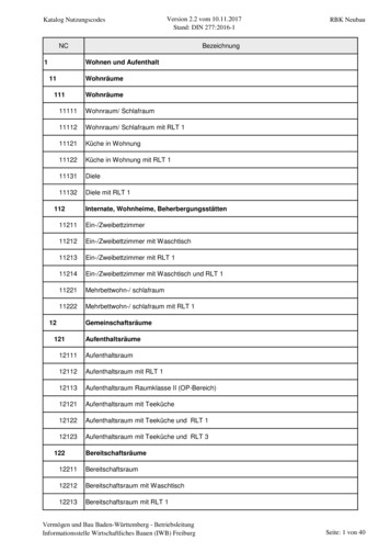
Post Hole Digger Storage StandAssembly InstructionsFor PD10, PD15, PD25 & PD35 Post Hole Diggers2085620776PD10 Storage StandFigure 1Before You Start!Manual No. 317-413MWhen you see this symbol, the subsequentinstructions and warnings are serious - followthem without exception. Your life and the lives ofothers depend on it!IMPORTANT: Before you begin, read theseinstructions and check to be sure all parts and toolsare accounted for. Please retain these installationinstructions for future reference and parts orderinginformation.Your Storage Stand is exclusively designed for your LandPride PD10, PD15, DP25 or PD35 Post Hole Diggers.Please read these installation instructions and your PostHole Digger Operator’s Manual thoroughly beforebeginning. Especially read information relating to safetyconcerns. Also included in the Operator’s Manual isimportant information on operation, adjustment,troubleshooting, and maintenance for this attachment(some manual sections do not apply to all accessories).A separate Parts Manual for your digger is available freeof charge at www.landpride.com or can be purchasedfrom your nearest Land Pride dealer. Have the model andserial number of your Storage Stand handy when placingan order.Manual Part Numbers: Operator’s Manual . . . . . . . . . . . . . . . . 317-048M Parts Manual . . . . . . . . . . . . . . . . . . . . . 317-048P Copyright 2020Printed 9/16/20PD15, PD25, and PD35 Storage StandFigure 2General InformationThese assembly instructions apply to the followingStorage Stand Accessories listed below:317-166A317-142APD10 Storage Stand . . . . . . . . . . . . . . . .Page 2PD15, PD25, & PD35 Storage Stand . . .Page 5Tools required: Safety glasses and work gloves Two 9/16" wrenches (PD15, PD25, & PD35 only) Two 3/4" wrenches One #13 metric wrench (PD10 only)Further AssistanceYour dealer wants you to be satisfied with your newstorage stand. If for any reason you do not understandany part of this manual or are not satisfied with theservice received, the following actions are suggested:1.Discuss the matter with your dealership servicemanager. Make sure he has had time to assist you.2. If you are still not satisfied, seek out the owner orgeneral manager and explain the question/problem.3. For further assistance write to:Land Pride Service Department1525 East North StreetP.O. Box 5060Salina, Ks. 67402-5060E-mail addresslpservicedept@landpride.com1
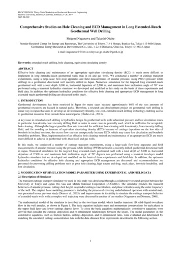
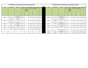
PD10 Storage Stand Assembly73920RigNOTE: Upper legs (#6B) are normallyshipped with decals (#12) installed. Ifshipped loose, they should be installed onthe two upper legs as follows:ht1.Lay the two legs (#6B) on the floor asshown with the bent ends at the topfacing in.2. Attach decals (#12) facing out andapproximately 8" down from the top oflegs (#6B). For proper label placementinstructions, refer to step 4 in the SafetyLabel Section of the Post Hole DiggerOperator’s Manual.LeftPD10 Stand AssemblyFigure 1-1PD10 Storage Stand AssemblyPart No. 317-166ARefer to Figure 1-1:A detailed listing of parts for this accessory kit is providedon page 4. Use the list as a checklist to inventory partsreceived. Please contact your local Land Pride dealer forany missing hardware.The Post Hold Digger Support Stand is shippedunassembled. Follow instructions below whenassembling the PD10 Post Hole Digger Stand.IMPORTANT: The stand is shipped with four legs.The upper legs (#6B) have decals (#12) and areinstalled inside lower legs (#6A) with the bent endspointing in as shown. The bent ends on lowerlegs (#6A) point out as shown.See Note in Figure 1-1 if decals (#12) are shippedloose in a bag.1.Attach lower legs (#6A) to upper legs (#6B) with1/2" x 1 1/4" bolts (#7B) and whiz nuts (#9).Do not tighten whiz nuts at this time.2. Attach cross bar (#4) to legs (#6A & #6B) with1/2" x 1 1/4" bolts (#7A) and whiz nuts (#9).Do not tighten whiz nuts at this time.23. Attach mount (#5) to upper legs (#6B) with1/2" x 1 1/4" bolts (#7C) and whiz nuts (#9). Do nottighten whiz nuts at this time.4. Draw all assembled whiz nuts (#9) up snug. Verifylegs (#6A) align evenly with legs (#6B) and the top ofthe cross bar (#4) is parallel with the top of the legs.Torque whiz nuts (#9) to 76 ft-lbs as noted below.a. Tighten whiz nuts (#9) on bolts (#7B) whilemaking sure the upper and lower legs align witheach other.b. Tighten whiz nuts (#9) on bolts (#7A) whilemaking sure the top of cross bar (#4) is parallelwith the top edge of legs (#6A & #6B).c. Tighten whiz nuts (#9) on bolts (#7C).5. Attach support angles s (#2) on the left side oftabs (C) on with 1/2" x 1 1/4" bolts (#7D) and nylocknuts (#10). Draw nylock nuts up snug and then backnut up one-half revolution.6. Attach support angles (#2) to the slotted holes intabs (C) with hand knobs (#11). Hand tighten knobs.7. Insert cradle pins (A) in slots (B) and securecradle (#3) to upper mount (#5) with handknobs (#11). Hand tighten knobs.8. Keep M8 x 1.25 bolts (#8) for attaching cradle (#3) tothe Post Hole Digger gearbox.Post Hole Digger Storage Stand Assembly Instructions Manual No. 317-413M9/16/20
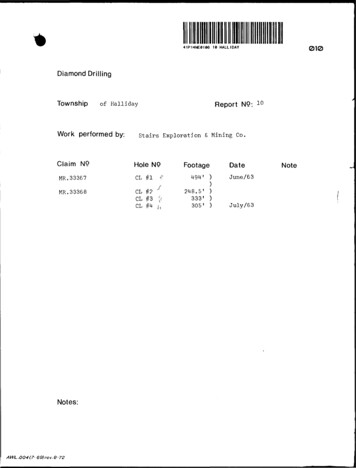
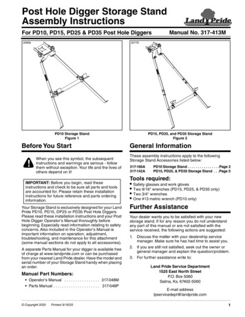
PD10 Cradle AssemblyPD10 Cradle Assembly20867Refer to Figure 1-2:The optional storage stand is used for storing thePost Hole Digger off the ground where moisture anddebris are more likely to cause damage to thecomponents. It will also assist the operator whilehooking-up and unhooking the unit.PD10 Storage Stand Assembly1.Unscrew locknuts (#11) and remove bolts (#10).Slide auger (#1) off of gearbox (#15).Remove existing bolts (#7), lock washers (#12),flat washers (#13), and auger guards (#3) fromunderside of gearbox (#14).Position cradle (#5) between auger guards (#3)and gearbox (#14). Make sure cradle pins (#2)are positioned to the back as shown.Attach cradle (#5) and guards (#3) to theunderside of gearbox (#14) with new M8 x 1.25bolts (#7), existing lock washers (#12), andexisting flat washers (#13). Torque bolts (#7)to 19 ft-lbs.Reattach auger (#1) to gearbox (#14) withexisting 1/2" x 3 1/2" auger bolts (#10) andlocknuts (#11). Torque locknuts to 76 ft-lbs.2.3.4.5.PD10 Storage Stand Operation!WARNINGTo avoid serious injury or death: Do not disconnect PostHole Digger from the tractor while on a steep incline.Injury to personnel and equipment may result.Attach storage stand (#8) to cradle (#5) as follows:1.2.3.4.5.6.7.Stop on solid, level ground, place tractor in parkor set tractor park brake, lower auger tip to theground, turn tractor engine off, and remove theignition key before dismounting the tractor.If you stop on a gentle slope, chock tractorwheels for an extra measure of safety.Make certain guide slots (#9) are securelypositioned over cradle pins (#2). Secure storagestand (#8) to the cradle with hand knobs (#6).Start tractor and lower boom (#4) to rest yokehitch pins (#15) in support angles (#16). Thesupport angles may require adjustment.Shut tractor down and disconnect three-pointhitch.Remove chocks if installed.Start tractor and drive away while being carefulnot to catch on the Post Hole Digger and/orStorage Stand (#8).9/16/20PD10 Storage Stand AssemblyFigure 1-2Post Hole Digger Storage Stand Assembly Instructions Manual No. 317-413M3
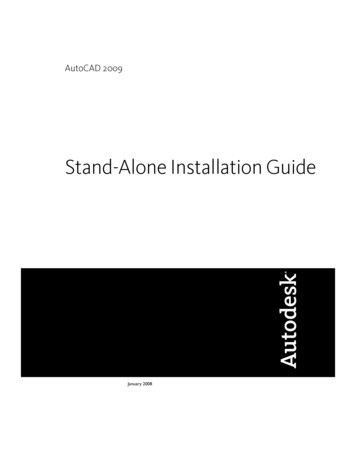
PD10 Cradle Assembly73917PD10 Storage Stand AssemblyItemPart No.Part 4C803-037C803-147C817-455C838-298CPD10 STAND ASSEMBLY . . . . . . . . . . . . . . . . . . . . . . . . . . . . . . . . . . . . . . . . . . . . 1PD STAND HITCH WELDMENT . . . . . . . . . . . . . . . . . . . . . . . . . . . . . . . . . . . . . . . 2PD10 STAND CRADLE WELDMENT . . . . . . . . . . . . . . . . . . . . . . . . . . . . . . . . . . . 1PD10 STAND CROSS BAR WLDMNT . . . . . . . . . . . . . . . . . . . . . . . . . . . . . . . . . . 1PD10 MOUNT . . . . . . . . . . . . . . . . . . . . . . . . . . . . . . . . . . . . . . . . . . . . . . . . . . . . . 1PD10 STAND LEG . . . . . . . . . . . . . . . . . . . . . . . . . . . . . . . . . . . . . . . . . . . . . . . . . 4HHCS 1/2-13X1 1/4 GR5 . . . . . . . . . . . . . . . . . . . . . . . . . . . . . . . . . . . . . . . . . . . . 8HHCS M8X1.25X20 GR8.8 . . . . . . . . . . . . . . . . . . . . . . . . . . . . . . . . . . . . . . . . . . . 4NUT HEX WHIZ 1/2-13 PLT GR5 . . . . . . . . . . . . . . . . . . . . . . . . . . . . . . . . . . . . . . 6NUT HEX NYLOCK 1/2-13 . . . . . . . . . . . . . . . . . . . . . . . . . . . . . . . . . . . . . . . . . . . 2KNOB 1/2-13 MALE THD 2 3/8OD . . . . . . . . . . . . . . . . . . . . . . . . . . . . . . . . . . . . . 4DECAL CAUTION DO NOT LEAN ON . . . . . . . . . . . . . . . . . . . . . . . . . . . . . . . . . . 24Post Hole Digger Storage Stand Assembly Instructions Manual No. 317-413MQty9/16/20
PD15, PD25, & PD35 Storage Stand Assembly73923RigNOTE: Upper legs (#6B) arenormally shipped with decals(#14) installed. If shipped loose,they should be installed on the twoupper legs as follows:ht1.LeftLay the two legs (#6B) on thefloor as shown with the bentends at the top facing in.2. Attach decals (#14) facing outand approximately 8" downfrom the top of legs (#6B). Forproper label placementinstructions, refer to step 4 inthe Safety Label Section ofthe Post Hole DiggerOperator’s Manual.PD15, PD25, and PD35 Stand AssemblyFigure 2-1PD15, PD25, & PD35 StorageStand AssemblyPart No. 317-142ARefer to Figure 2-1:A detailed listing of parts for this accessory kit is providedon page 7. Use the list as a checklist to inventory partsreceived. Please contact your local Land Pride dealer forany missing hardware.The Post Hold Digger Support Stand is shippedunassembled. Follow instructions below whenassembling the PD15, PD25, or PD35 Post Hole DiggerStand.IMPORTANT: The stand is shipped with four legs.The upper legs (#6B) have decals (#14) and areinstalled inside lower legs (#6A) with the bent endspointing in as shown. The bent ends on lower legs(#6A) point out as shown.See Note in Figure 2-1 if decals (#14) are shippedloose in a bag.1.Attach lower legs (#6A) to upper legs (#6B) with1/2" x 1 1/4" bolts (#8A & #8B) and whiznuts (#9). Do not tighten whiz nuts at this time.2. Attach cross bar (#4) to lower legs (#6A) with1/2" x 1 1/4" bolts (#8D) and whiz nuts (#9).Do not tighten whiz nuts at this time.9/16/203. Attach mount (#5) to upper legs (#6B) with1/2" x 1 1/4" bolts (#8C) and whiz nuts (#9). Do nottighten whiz nuts at this time.4. Draw all assembled whiz nuts (#9) up snug. Verifylegs (#6A) align evenly with legs (#6B) and the top ofthe cross bar (#4) is parallel with the top of the legs.Torque whiz nuts (#9) to 76 ft-lbs as noted below.a. Tighten whiz nuts (#9) on bolts (#8A & #8B) whilemaking sure legs (#6A & #6B) align with eachother.b. Tighten whiz nuts (#9) on bolts (#8D) whilemaking sure the top of cross bar (#4) is parallelwith the top edge of legs (#6A).c. Tighten whiz nuts (#9) on bolts (#8D).5. Attach support angles (#3) on the left side of tabs (C)with 1/2" x 1 1/4" bolts (#8E) and nylock nuts (#10).Draw nylock nuts up snug and then back nuts up onehalf revolution.6. Attach support angles (#3) to the slotted holes with1/2" x 1 1/4" bolts (#8F), lock washers (#11), and flatwashers (#12). Torque bolts (#8F) to 76 ft-lbs.7. Insert cradle pins (A) in guide slots (B) and securecradle (#2) to upper mount (#5) with knobs (#13).Hand tighten knobs.8. Keep 3/8" x 1" bolts (#7) for attaching cradle (#2) tothe Post Hole Digger gearbox.Post Hole Digger Storage Stand Assembly Instructions Manual No. 317-413M5
PD15, PD25, & PD35 Cradle AssemblyPD15, PD25, & PD35Cradle Assembly20872Refer to Figure 2-2:The optional storage stand is used for storing thePost Hole Digger off the ground where moisture anddebris are more likely to cause damage to thecomponents. It will also assist the operator whilehooking-up and unhooking the unit.Storage Stand Assembly1.Unscrew locknuts (#9) and remove1/2"-13 x 3 1/2" GR5 hex head bolts (#8). Slideauger (#4) off of gearbox (#13).Remove existing bolts (#7), lock washers (#11),flat washers (#10), and auger guards (#2) fromunderside of gearbox (#13).Position cradle (#3) between auger guards (#2)and gearbox (#13). Make sure cradle pins (#5)are positioned to the back as shown.Attach cradle (#3) and guards (#2) to undersideof gearbox (#13) with new 3/8" 16 x 1" bolts (#7),existing lock washers (#11), and existing flatwashers (#10). Torque bolts (#7) to 31 ft-lbs.Attach auger (#4) to gearbox output shaft withauger bolts (#8) and locknuts (#9).2.3.4.5.Storage Stand Operation!WARNINGTo avoid serious injury or death: Do not disconnect PostHole Digger from the tractor while on a steep incline.Injury to personnel and equipment may result.Attach storage stand (#14) to cradle (#3) as follows:1.2.3.4.5.6.7.6Stop on solid, level ground, place tractor in parkor set tractor park brake, lower auger tip to theground, turn tractor engine off, and remove theignition key before dismounting the tractor.If you stop on a gentle slope, chock tractorwheels for an extra measure of safety.Make certain guide slots (#6) are securelypositioned over cradle pins (#5). Secure storagestand (#14) to the cradle with knobs (#12).Start tractor and lower boom (#1) to rest yokehitch pins (#15) in support angles (#16). Thesupport angles may require adjustment.Shut tractor down and disconnect three-pointhitch.Remove chocks if installed.Start tractor and drive away while being carefulnot to catch on the Post Hole Digger and/orStorage Stand (#14).Post Hole Digger Storage Stand Assembly Instructions Manual No. 317-413MPD15, 25, and 35 Storage Stand AssemblyFigure 2-29/16/20
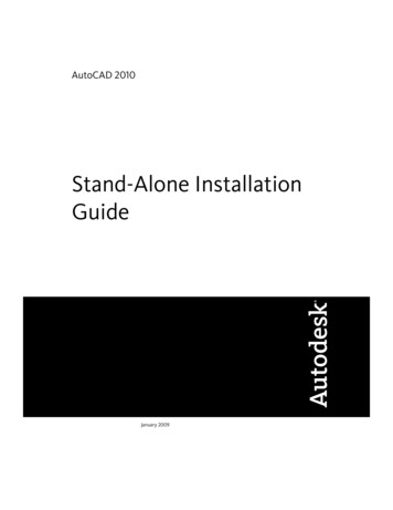
PD15, PD25, & PD35 Cradle Assembly73918PD15, PD25 & PD35 Storage Stand Parts ListItemPart No.Part 8-298CPD15/25/35 STAND ASSEMBLY . . . . . . . . . . . . . . . . . . . . . . . . . . . . . . . . . . . . . . . 1PD STAND CRADLE WELDMENT . . . . . . . . . . . . . . . . . . . . . . . . . . . . . . . . . . . . . 1PD STAND HITCH WELDMENT . . . . . . . . . . . . . . . . . . . . . . . . . . . . . . . . . . . . . . . 2PD15/25/35 STAND BRACE WLDMNT . . . . . . . . . . . . . . . . . . . . . . . . . . . . . . . . . . 1PD15/25/35 STAND UPPER MOUNT . . . . . . . . . . . . . . . . . . . . . . . . . . . . . . . . . . . 1PD15/25/35 STAND LEG . . . . . . . . . . . . . . . . . . . . . . . . . . . . . . . . . . . . . . . . . . . . 4HHCS 3/8-16X1 GR5 . . . . . . . . . . . . . . . . . . . . . . . . . . . . . . . . . . . . . . . . . . . . . . . 4HHCS 1/2-13X1 1/4 GR5 . . . . . . . . . . . . . . . . . . . . . . . . . . . . . . . . . . . . . . . . . . . 12NUT HEX WHIZ 1/2-13 PLT GR5 . . . . . . . . . . . . . . . . . . . . . . . . . . . . . . . . . . . . . . 8NUT HEX NYLOCK 1/2-13 . . . . . . . . . . . . . . . . . . . . . . . . . . . . . . . . . . . . . . . . . . . 2WASHER LOCK SPRING 1/2 PLT . . . . . . . . . . . . . . . . . . . . . . . . . . . . . . . . . . . . . 2WASHER FLAT 1/2 SAE PLT . . . . . . . . . . . . . . . . . . . . . . . . . . . . . . . . . . . . . . . . . 2KNOB 1/2-13 MALE THD 2 3/8OD . . . . . . . . . . . . . . . . . . . . . . . . . . . . . . . . . . . . . 2DECAL CAUTION DO NOT LEAN ON . . . . . . . . . . . . . . . . . . . . . . . . . . . . . . . . . . 29/16/20Post Hole Digger Storage Stand Assembly Instructions Manual No. 317-413MQty7
Corporate Office: P.O. Box 5060Salina, Kansas 67402-5060 USAwww.landpride.com
PD10 Cradle Assembly PD10 Cradle Assembly Refer to Figure 1-2: The optional storage stand is used for storing the Post Hole Digger off the ground where moisture and debris are more likely to cause damage to the components. It will also assist the operator while hooking-