Transcription
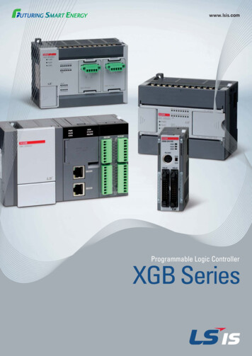
HyPLC: Hybrid Programmable Logic ControllerProgram Translation for VerificationLuis GarciaStefan MitschAndré PlatzerElectrical and Computer EngineeringDepartmentUniversity of California, Los AngelesLos Angeles, CA, USAgarcialuis@ucla.eduComputer Science DepartmentCarnegie Mellon UniversityPittsburgh, PA, USAsmitsch@cs.cmu.eduComputer Science DepartmentCarnegie Mellon UniversityPittsburgh, PA, USAaplatzer@cs.cmu.eduABSTRACTKEYWORDSProgrammable Logic Controllers (PLCs) provide a prominent choiceof implementation platform for safety-critical industrial control systems. Formal verification provides ways of establishing correctnessguarantees, which can be quite important for such safety-criticalapplications. But since PLC code does not include an analytic modelof the system plant, their verification is limited to discrete properties. In this paper, we, thus, start the other way around with hybridprograms that include continuous plant models in addition to discrete control algorithms. Correctness properties of hybrid programscan be formally verified in the theorem prover KeYmaera X thatimplements differential dynamic logic, dL, for hybrid programs.After verifying the hybrid program, we now present an approachfor translating hybrid programs into PLC code. The new HyPLCtool implements this translation of discrete control code of verifiedhybrid program models to PLC controller code and, vice versa, thetranslation of existing PLC code into the discrete control actionsfor a hybrid program given an additional input of the continuousdynamics of the system to be verified. This approach allows for thegeneration of real controller code while preserving, by compilation, the correctness of a valid and verified hybrid program. PLCsare common cyber-physical interfaces for safety-critical industrialcontrol applications, and HyPLC serves as a pragmatic tool forbridging formal verification of complex cyber-physical systems atthe algorithmic level of hybrid programs with the execution layerof concrete PLC implementations.Industrial control, programming languages, formal verification,semantics, compilationCCS CONCEPTS Computing methodologies Model verification and validation; Computer systems organization Embedded andcyber-physical systems; Software and its engineering Compilers.Permission to make digital or hard copies of all or part of this work for personal orclassroom use is granted without fee provided that copies are not made or distributedfor profit or commercial advantage and that copies bear this notice and the full citationon the first page. Copyrights for components of this work owned by others than ACMmust be honored. Abstracting with credit is permitted. To copy otherwise, or republish,to post on servers or to redistribute to lists, requires prior specific permission and/or afee. Request permissions from permissions@acm.org.ICCPS ’19, April 16–18, 2019, Montreal, QC, Canada 2019 Association for Computing Machinery.ACM ISBN 978-1-4503-6285-6/19/04. . . 15.00https://doi.org/10.1145/3302509.3311036ACM Reference Format:Luis Garcia, Stefan Mitsch, and André Platzer. 2019. HyPLC: Hybrid Programmable Logic Controller Program Translation for Verification . In 10thACM/IEEE International Conference on Cyber-Physical Systems (with CPS-IoTWeek 2019) (ICCPS ’19), April 16–18, 2019, Montreal, QC, Canada. ACM, NewYork, NY, USA, 10 pages. ONThere has been an increased emphasis on the verification and validation of software used in embedded systems in the context of industrial control systems (ICS). ICS represent a class of cyber-physicalsystems (CPS) that provide monitoring and networked process control for safety-critical industrial environments, e.g., the electricpower grid [1], railway safety [2], nuclear reactors [3], and watertreatment plants [4]. A prominent choice of implementation platform for many ICS applications are programmable logic controllers(PLCs) that act as interfaces between the cyber world–i.e., the monitoring entities and process control–and the physical world–i.e., theunderlying physical system that the ICS is sensing and actuating.Efforts to verify the correctness of PLC applications focus on thecode that is loaded onto these controllers [5–8]. Existing methodsare based on model checking of safety properties specified in modaltemporal logics, e.g., Linear Temporal Logic (LTL) [9] and Computation Tree Logic (CTL) [10]. However, since PLC code does notinclude a model of the system plant, such analyses are limited tomore superficial, discrete properties of the code instead of analyzingsafety properties of the resulting physical behavior.In this paper, we thus start from hybrid systems models of ICS,in which the discrete computations of controllers run together withthe continuous evolution of the underlying physical system. Thatway, correctness properties that consider both control decisionsand physical evolution can be verified in the theorem prover KeYmaera X [11]. The verified hybrid programs can then be compiledto PLC code and executed as controllers. The reverse compilationfrom PLC code to hybrid programs facilitates verifying existingPLC code with respect to pre-defined models of the continuousplant dynamics.In this paper, we present HyPLC, a tool that compiles verified hybrid systems models into PLC code and vice versa. Figure 1 depicts ahigh-level overview of the bidirectional compilation provided by HyPLC. The hybrid models are specified in differential dynamic logic,dL [12–14], which is a dynamic logic for hybrid systems expressed
ICCPS ’19, April 16–18, 2019, Montreal, QC, CanadaIndustrial Control SystemVerifierVerifiable Hybrid ProgramCentral Control (SCADA)Luis Garcia, Stefan Mitsch, and André PlatzerA [{ %; '()*;plant}*] I1I2I3I4PLCControlLogicIf(I1 I2)ELSIF(I3 I4)END IF;THEN O1: 0;THEN O2: 1;HMIO1Control LogicO2HyPLCFirmware Compilation rules Preserves semanticsI/OInputPhysical Planty’ -Safety Theorem Prover(KeYmaera X)SensorCyber WorldICS NetworkActuatorSensorScan CycleCPUOutputPhysical WorldActuatorHardwareNetworkFigure 2: The PLC scan cycle in the context of ICSFigure 1: HyPLC provides a bidirectional translation of thediscrete control of a verifiable hybrid program expressedin dL and the control logic code that runs on a PLC in thecontext of a cyber-physical industrial control systemas hybrid programs. Compiling hybrid programs to PLC code generates deterministic implementations of the controller abstractionstypically found in hybrid programs, which focus on capturing thesafety-relevant decisions for verification purposes concisely withnondeterministic modeling concepts. Nondeterminism in hybridprograms can be beneficial for verification since nondeterministicmodels address a family of (control) programs with a single proofat once, but is detrimental to implementation with Structured Text(ST) programs on PLCs. Therefore, in this paper we focus on hybridprograms in scan cycle form. The compilation adopts the IEC 611313 standards for PLCs [15]. Compiling PLC code to dL and hybridprograms, implemented using the ANTLR parser generator [16],provides a means of analyzing PLC code on pre-defined models ofcontinuous evolution with the deductive verification techniques ofKeYmaera X. The core contributions of this paper lie in our correctness proofs for the bidirectional compilation, so that both directionsof compilation yield a way of obtaining code with safety guarantees (assuming no floating-point arithmetic errors arise). Finally, weevaluated our tool on a water treatment testbed [17] that consistsof a distributed network of PLCs.The rest of the paper is organized as follows. Section 2 providesbackground information. Section 3 introduces compilation rulesfor terms in both languages and describes how the semantics ispreserved. Section 4 and Section 5 describe the compilation offormulas and programs, respectively, and include formal proofs ofcorrectness and preservation of safety across compilation. Section 6presents our evaluation of HyPLC on a water treatment case study.We discuss the limitations of HyPLC and conclude in Section 7.2PRELIMINARIESThis section explains the preliminaries necessary to understand theunderlying concepts of HyPLC. We first provide a brief overviewof PLCs, including how they are integrated into ICS as well as theassociated programming languages and software model as definedby the IEC 61131-3 standard for PLCs [15]. We then discuss previous works in formal verification of PLC programs, followed by anoverview of the dynamic logic and hybrid program notation usedby HyPLC.2.1Programmable Logic ControllersPart 3 of the IEC 61131 standards [15] for PLCs specifies both thesoftware architecture as well as the programming languages for thecontrol programs that run on PLCs. We will provide the requisiteknowledge for understanding the assumptions made by HyPLC.PLCs in the context of ICS. Figure 2 shows how PLCs are integrated into ICS as well as a schematic overview of the PLC scancycle. Scan cycles are typical control-loop mechanisms for embedded systems. The PLC “scans” the input values coming from thephysical world and processes this system state through the controllogic of the PLC, which is essentially a reprogrammable digital logiccircuit. The outputs of the control logic are then forwarded throughthe output modules of the PLC to the physical world. HyPLC focuses on hybrid programs of a shape that fits to this scan cyclecontrol principle using time-triggered models.Programming languages and software execution model. HyPLC focuses on bidirectional compilation of the Structured Text (ST)language, which is a textual language similar to Pascal that, forformal verification purposes [18], can be augmented to subsumeall other languages1 defined by the IEC 61131-3 standard. For thesoftware execution model, we refer to the literature [15]. We onlyconsider a single-resource configuration of a PLC that has a singletask associated with a particular program that executes for a particular interval, 𝜀. Because, it is a single task configuration, we donot consider priority scheduling.2.2PLC Programming Language VerificationDue to their wide use, there have been numerous works regardingthe verification of safety properties of PLC programming languages.Rausch et al. [19] modeled PLC programs consisting only of Booleanvariables, static single assignment of variables, no special functionsor function blocks, and no jumps except subroutines without recursion. Such an approach was an initial attempt to provide formalverification of discrete properties of the system, i.e., properties thatcan be derived and verified purely from the software, ignoring thephysical behavior of its plant. Similarly, other approaches havebeen presented whose safety properties are specified and modeledusing linear temporal logic [20, 21] or by representing the system asa finite automaton [22, 23] or real-time automata [24] . The formal1 ladder diagrams (LD), function block diagrams (FBD), sequential function charts(SFC), and instruction list (IL)
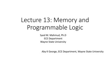
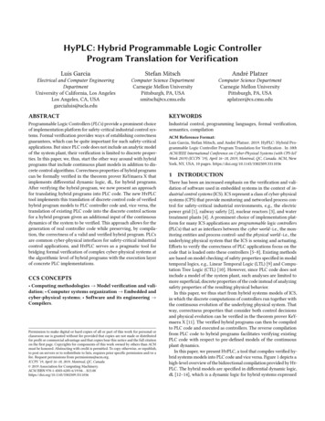
HyPLC: Hybrid PLC Translation for Verificationverification of such systems is limited by state-space explorationtechniques, e.g., there will be an uncountable number of statesfor continuous systems because time is a variable. As such, thesetechniques will only be able to explore a subset of the states.Conversely, there have been several works regarding the generation of PLC code based on the formal models of PLC code. PLCSpecif [6] is a framework for generating PLC code based on finiteautomata representations of the PLC. Although this framework provides a means of generating PLC code based on formally verifiedmodels, the formal verification has the aforementioned limitationsof providing correctness guarantees for discrete properties of thePLC code that can be verified for a finite time horizon. The approachpresented by Sacha [25] has similar limitations since it uses statemachines to represent finite-state models of PLC code. Darvas et al.also used PLCSpecif for conformance checking of PLC code againsttemporal properties [26]. Flordal et al. automatically generated PLCcode for robotic arms based on generated zone models to ensure thearms do not collide with each other as well as to prevent deadlocksituations [27]. The approach generates a finite-state model of therobot CPS environment that is then used to generate supervisorycode within the PLC that controls its arm. The approach abstractsthe PLC’s discrete properties and does not incorporate the PLC’stiming properties into the physical plant model. Furthermore, this isa domain-specific approach for robot simulation environments anddoes not provide generalizability nor a means of formal verificationof the initially generated finite-state models.VeriPhy [28] compiles CPS models specified in dL to verifiedexecutables that sandbox controllers with safe fallback control andmonitor for expected plant behavior. The VeriPhy pipeline combines multiple tools to bridge implementation and arithmetic gapsand provide proofs that safety is preserved when compiling to acontroller executable. HyPLC provides bi-directional compilationin the particular context of PLC scan cycles but ignores arithmeticrounding and is not formally verified. Majumdar et al. also explored equivalence checking of C code and an associated SIMULINKmodel [29]. Although such an approach is useful for modelling thebehavior of C code in a control system model, additional efforts areneeded to interface such a model with verification tools such asKeYmaera X as well as to model the behavior of PLCs.2.3Differential Dynamic Logic and HybridProgramsHyPLC works on models that have been specified in differentialdynamic logic (dL) [12–14], a logic that models hybrid systems andcan be formally verified with a sound proof calculus. The formalizedmodels that use dL are referred to as hybrid programs. As with ST,we will recall the syntax and semantics of dL and hybrid programsas needed throughout the course of this paper.The modal operators [𝛼] and ⟨𝛼⟩ are used to formally describethe behavioral properties the system has to satisfy. If 𝛼 denotes ahybrid program, and 𝜙 and 𝜓 are formulas, then the dL formula𝜙 [𝛼]𝜓means “if 𝜙 is initially satisfied, then 𝜓 holds true for all the statesafter executing the hybrid program 𝛼”. This way, safety propertiesICCPS ’19, April 16–18, 2019, Montreal, QC, CanadaPLC1f1x1HV1HPLValvex2Flow Meterf2PumpV2LWater Level SensorFigure 3: The first process control components for a watertreatment testbed [17].can be encoded for a model 𝛼. We use the modeling pattern𝐴 [{ctrl; plant} ]𝑆,where 𝐴 represents assumptions on the initial state of the system,ctrl describes the discrete control transitions of the system, plantdefines the continuous physical behavior of the system, and 𝑆 isthe safety property we want to prove. In this pattern, control andplant are repeated any number of times, as indicated with thenondeterministic repetition operator .FV(𝜙) refers to the free variables and BV(𝜙) refers to the boundvariables of formula 𝜙 (accordingly for terms and programs) [13].2.4Use Case: Water Treatment TestbedAs a running example, we will use a simple water tank componenttaken from the first of six control processes of a water treatmenttestbed [17], depicted in Figure 3. This process is responsible fortaking in water from a raw water source and feeding it into a tank.This water will then be pumped out into a second tank to be treatedwith chemicals. For this first process, the PLC is responsible forcontrolling the inflow of water for both tanks by opening or closingvalves, 𝑉1 and 𝑉2 , as well as the outflow of water to the secondtank by running the pump, 𝑃. The PLC monitors the water level ofboth water tanks, 𝑥 1 and 𝑥 2 , to ensure that 𝑉1 and 𝑉2 , respectively,are closed before each respective tank overflows beyond an upperbound, 𝐻 . The PLC is additionally responsible for protecting theoutflow pump, 𝑃, by ensuring that the pump is off if the water levelof 𝑥 1 is below a lower threshold, 𝐿, or if the flow rate of the pump,𝑓2 , is below a certain lower threshold, 𝐹𝐿 (not shown in Figure 3).Figure 4 shows a simplified representation of the actual ST code thatis loaded onto the PLC for a particular sample rate of 𝜀 for all theassociated sensors. In this model, the flow rate for the incoming rawwater, 𝑓1 , is not incorporated into the process control. The real system simply monitors the value of this flow rate without establishinga physical dependency. The upper limits of the water tank level, 𝐻 1and 𝐻 2 , and the lower limits, 𝐿1 and 𝐿2 , represent trigger levels thatare below and above, respectively, the actual safety thresholds, 𝐻𝐻and 𝐿𝐿 . The trigger values were determined empirically [17]; ourproofs will find and verify symbolic characterizations of the triggervalues. This model will be used throughout the paper to illustratehow an existing ST program can be systematically compiled to thediscrete control of a hybrid program and updated if necessary toensure safe operation of the ICS.
ICCPS ’19, April 16–18, 2019, Montreal, QC, CanadaLuis Garcia, Stefan Mitsch, and André PlatzerPROGRAM p r o g 0/ data declaration /VAR INPUT x1 , x2 , f 1 , f 2 : REAL ; END VARVAR OUTPUT V1 , V2 , P : BOOL ;END VAR/ s t r u c t u r e d t e x t program s t a t e m e n t s /IF ( x1 H1 ) THENV1 : 0 ;ELSEIF ( x1 L1 ) THENV1 : 1 ;END IF ;END IF ;IF ( x2 L2 ) THENP : 1 ; V2 : 1 ;END IF ;IF ( x1 LL OR f 2 FL OR x2 H2 ) THENP : 0 ; V2 : 0 ;END IF ;END PROGRAM/ PLC c o n f i g and c o mp u t i n g t a s k a s s i g n m e n t /CONFIGURATION C o n f i g 0RESOURCE R e s 0 ON PLCTASK Main ( INTERVAL : T#1 s , PRIORITY : 0 ) ;PROGRAM I n s t 0 WITH Main : p r o g 0 ;END RESOURCEEND CONFIGURATIONmemory and directly affect the sensing and actuation of the cyberphysical system for a particular context. As such, these values willneed to be abstracted to represent the terms of an equivalent hybridprogram. We will first discuss syntax of the terms in both languagesand then define the semantics-preserving compilation.Notation. We write ST (𝜃 ) for the result of compiling a hybridprogram term, 𝜃 , to an ST term, and we write HP (𝜃 ) to representcompiling an ST term to a hybrid program term. We write ST (𝜃 ) 𝑠when 𝑠 is the result of compiling 𝜃 to an ST term, and HP (𝑠) 𝜃 when𝜃 is the result of compiling 𝑠 to a dL term. This notation will also beused for the bidirectional compilation of formulas and programs.Figure 4: ST program for simplified PLC process control ofthe system in Figure 333.1𝜃, 𝜂 :: 𝑎 𝑥COMPILATION OF TERMSCompilation approach overview. Compilation between ST andhybrid programs bases on two main ingredients: the syntax of thelanguages, given in grammars, define their notation; the languagesemantics give meaning to the syntactic constructs. Compilationtranslates from one syntax to another, but it must be done in a waythat preserves the semantics of the compiled programs.With compilation rules, we define how to compile a term, formula, or program in the source syntax into a corresponding term,formula, or program of the target syntax. Each rule will compilea certain program operator, and often invoke compilation on theoperands. For example, ST (𝜙 𝜓 ) ST (𝜙) AND ST (𝜓 ) compiles conjunction in hybrid program formulas into conjunction AND in STof the recursively compiled sub-formulas 𝜙 and 𝜓 . Here, ST (𝜙 𝜓 )means that we compile hybrid program formula 𝜙 𝜓 into an STformula; the operator describes how the compilation is done.With proofs of compilation correctness we then show that thecompilation rules preserve the semantics in a way that will allow usto conclude safety of an ST program from a safety proof of a hybridprogram. The proofs exploit the recursive nature of the compilationrules and apply structural induction on the program syntax constructs, where we inductively justify each compilation rule fromits easier pieces, assuming absence of arithmetic inaccuracies andbasing on the hypothesis that the easier pieces are correctly builtfrom the base constructs (e.g. complicated terms built from numbersand variables).For terms and propositional formulas, the compilation rules arestraightforward. The main syntactic difference is between nondeterministic choices in hybrid programs and if-then-else constructsin ST. Aligning the semantics in the compilation correctness proofs,however, requires more work: the semantics of ST is given as anoperational semantics [18], which describes the effects of takinga step in a program, whereas the semantics of hybrid programs isdenotational, which describes the reachability relation of a program.Term compilation overview. In this section, we will define birectional compilation rules of the arithmetic terms in both hybridprograms and ST for PLCs. The terms of ST are the leaf elementsof ST expressions that represent the values stored in the PLC’sGrammar DefinitionsIn order to compile terms between both languages while preservingthe respective semantics, we first define the grammar for bothlanguages.Grammar of ST terms. The terms of ST considered in this paperare defined by the grammar: 𝜃 𝜃 𝜂 where { , , , / , }and where 𝑎 is a number literal, 𝑥 𝑉 is an ST variable, and 𝑉 is thesubset of all ST variables, and both number literals and variables arerestricted to LReal2 of the numeric elementary data types definedby the IEC 61131-3 standard.Grammar of dL terms. The translatable terms of dL and hybridprograms [12, 13] are defined by the grammar:𝜃, 𝜂 :: 𝑥 𝑛 𝜃 𝜂 where { , , ·, / , ˆ}and where 𝑥 𝑉 is a variable and 𝑉 is the set of all variables. Thegrammar allows the use of number literals 𝑛 as functions withoutarguments that are to be interpreted as the value they represent.Next, we provide the bidirectional compilation rules of termsand prove term compilation correctness.3.2Compilation RulesWe will first define compilation rules for the terminal expressions,referred to as atomic terms, and compose the other expressionsfollowing the recursive nature of the grammars.Atomic terms. Atomic terms in hybrid programs include variables and number literals. For the sake of simplicity, we do notconsider functions within hybrid programs as we want to focus onthe core elements of discrete control, and we assume that the datatype LReal of the IEC 61131-3 standard coincides with mathematicalreals. In practice, when a PLC implements LReal with floating pointnumbers, this assumption can be met with an appropriate soundencoding using, for example, interval arithmetic as verified in [28].HyPLC compiles number literals and variables of hybrid programs, which evaluate to mathematical reals, to numbers and variables of data type LReal of the IEC 61131-3 standard as follows:Number literals 𝑛 and variables 𝑥 then do not need conversion, soST (𝑛) 𝑛 and HP (𝑛) 𝑛, as well as ST (𝑥) 𝑥 and HP(x) 𝑥.Next, we inductively define the compilation rules for arithmeticoperations.Arithmetic operations. Arithmetic operations are similarly defined in an inductive fashion in similar syntax in both languages,2 LRealvariables are 64-bit values represented as floating points from the IEC 60559standard.
HyPLC: Hybrid PLC Translation for Verificationwhich makes translation of terms 𝜃 and 𝜂 straightforward as follows,where { , , /}:ICCPS ’19, April 16–18, 2019, Montreal, QC, Canadain a straightforward way:ST (true) TRUEHP (TRUE) trueST (false) FALSEHP (FALSE) falseST ( (𝑥)) ( ST (𝑥))HP ( (𝑥)) ( HP (𝑥))ST (𝜃 𝜂) ST (𝜃 ) ST (𝜂)HP (𝜃 𝜂) HP (𝜃 ) HP (𝜂)Comparisons are directly compiled as follows:ST (𝜃 · 𝜂) ST (𝜃 ) ST (𝜂)HP (𝜃 𝜂) HP (𝜃 ) · HP (𝜂)ST (𝜃 𝜂) ST (𝜃 ) ST (𝜂)HP (𝜃 𝜂) HP (𝜃 ) HP (𝜂)ST (𝜃 ˆ 𝜂) ST (𝜃 )**ST (𝜂)HP (𝜃 **𝜂) HP (𝜃 ) ˆ HP (𝜂)ST (𝜃 𝜂) ST (𝜃 ) ST (𝜂)HP (𝜃 𝜂) HP (𝜃 ) HP (𝜂)ST (𝜃 𝜂) ST (𝜃 ) ST (𝜂)HP (𝜃 𝜂) HP (𝜃 ) HP (𝜂)We now provide the Lemmas for correctness of the translationof terms in both directions. As in [18], we write (𝜃, 𝜈) 𝑎 𝑐 toexpress that in ST a term 𝜃 evaluates to 𝑐 in context 𝜈. We write𝜈 [[𝜃 ]] 𝑐 to express that in dL a term 𝜃 evaluates to 𝑐 at state 𝜈 [13].Details on the dL semantics and ST semantics used in the proof canbe found in the associated appendices of the full report [30].Lemma 3.1 (Correctness of term compilation). Assumingabsence of arithmetic inaccuracies in LReal: if (𝜃, 𝜈) 𝑎 𝑐 then𝜈 [[ HP (𝜃 )]] 𝑐; conversely, if 𝜈 [[𝜃 ]] 𝑐 then ( ST (𝜃 ), 𝜈) 𝑎 𝑐.ST (𝜃 𝜂) ST (𝜃 ) ST (𝜂)HP (𝜃 𝜂) HP (𝜃 ) HP (𝜂)ST (𝜃 𝜂) ST (𝜃 ) ST (𝜂)HP (𝜃 𝜂) HP (𝜃 ) HP (𝜂)ST (𝜃 𝜂) ST (𝜃 ) ST (𝜂)HP (𝜃 𝜂) HP (𝜃 ) HP (𝜂)The compilation rules for the atomic formulas are the basis forcompiling compound formulas.Logical formulas. Logical connectives , , are straightforward,whereas , are rewritten for compilation (similar for XOR):ST ( (𝜙)) NOT( ST (𝜙))Proof. By structural induction on term operators, see the associated appendix in the full report [30]. HP (NOT(𝜙)) ( HP (𝜙))We next define how the compilation of terms is leveraged tocompile the formulas of both languages in both directions.HP (𝜙 AND 𝜓 ) HP (𝜙) HP (𝜓 )4ST (𝜙 𝜓 )COMPILATION OF FORMULASIn this section, we compile modality- and quantifier-free formulasused in tests in hybrid programs and conditional expressions of STstatements. As was done with the terms of each language, we firstdiscuss the syntax of the formulas for both languages.4.1Grammar DefinitionsGrammar of ST formulas. ST formulas are used in conditionalexpressions defined by the IEC 61131-3 standard as follows.𝜙,𝜓 :: TRUE FALSE 𝜃 ST 𝜂 NOT(𝜙) 𝜙 ST 𝜓where ST { , , , , , }and ST {AND, OR, XOR}The values TRUE and FALSE represent the two Boolean values aconditional expression can take upon evaluation, 𝜃 and 𝜂 are STterms, operator ST ranges over relational operators used in ST,operator ST ranges over logical operators between two formulas,and NOT(𝜙) is the logical negation of a formula 𝜙.Grammar of dL formulas. The truncated grammar for modalityand quantifier-free formulas in dL that we consider in this paper isbuilt using propositional connectives , , , , [12] as follows:𝜙,𝜓 :: true false 𝜃 HP 𝜂 𝜙 𝜙 HP 𝜓where HP { , , , , , } and HP { , , , }and where 𝜃 and 𝜂 are dL terms. Wwe present the compilation rulesand the formula compilation correctness proof for these grammars.4.2Compilation RulesAtomic formulas. Atomic formulas in both languages comprisethe literals true and false and comparisons of terms and are compiled ST (𝜙) AND ST (𝜓 )ST (𝜙 𝜓 ) ST (𝜙) OR ST (𝜓 )HP (𝜙 OR 𝜓 ) HP (𝜙) HP (𝜓 )ST (𝜙 𝜓 ) ST ( 𝜙 𝜓 )ST (𝜙 𝜓 ) NOT( ST (𝜙) XOR ST (𝜓 ))HP (𝜙 XOR 𝜓 ) ( HP (𝜙) HP (𝜓 ))We now prove correctness of the compilation of formulas in bothdirections. In ST, we write (𝜙, 𝜈) 𝑎 as in [18] and in dL 𝜈 𝜙to say that formula 𝜙 is true at state 𝜈 as in [13].Lemma 4.1 (Correctness of formula compilation). Formulasevaluate equivalently: 𝜈 𝜙 iff ( ST (𝜙), 𝜈) 𝑎 and, conversely,(𝜙, 𝜈) 𝑎 iff 𝜈 HP (𝜙).Proof. By structural induction on formula operators, see theassociated appendix in the full report [30]. 5COMPILATION OF PROGRAMSNow that we know how to correctly compile terms and formulasin both languages, we turn to compiling program constructs. Sincethese programs, when executed on a PLC, interact with the physicalworld, our overall goal is to provably establish safety properties ofthe physical behavior of an ICS. To this end, we again show compilation correctness with respect to the semantics of the languages,which will serve as a stepping stone to describe the program effectin the larger context of the PLC scan cycle.We first provide an overview of our hybrid system model of aPLC scan cycle, before we introduce the grammars and compilationrules for both languages and prove compilation correctness.5.1Scan Cycle Hybrid System ModelWe model the PLC scan cycle as a hybrid program of a particularshape—referred to as a hybrid program in scan cycle normal form—in order for safety properties verified about a hybrid program todirectly transfer to its implementation in ST.
ICCPS ’19, April 16–18, 2019, Montreal, QC, CanadaHybrid Program Scan Cycle:(Normal Form)A [(i : ; u ctrl(x,i); t : 0; {x’ f(x,u); t’ 1 & t -})*] Sexecution time -PLC Scan Cycle:Input ScanControl Logicix’ f(x,u)non-deterministic inputplantOutput ScanLuis Garcia, Stefan Mitsch, and André Platzer𝑠 1 has finished its execution. While Structured Text supports several other control structures such as finitely bounded loops andcase-statements, these can be represented as a series of if-then-elsestatements. The dL grammar is composed in a similar fashion.Grammar of dL programs. The grammar for PLC-translatable dLhybrid programs is defined as follows.𝛼, 𝛽 :: 𝑥 : 𝜃 (?𝜙; 𝛼) 𝛽 (?𝜙; 𝛼) (? 𝜙; 𝛽)(?𝜙; 𝛼) ? 𝜙 𝛼; 𝛽Figure 5: Hybrid system model of a PLC scan cycleFigure 5 provides an overview of the components of a hybridprogram in scan cycle normal form and how they relate to a PLCscan cycle. A PLC scan cycle is a periodic process that, on eachiteration, scans the inputs, then executes the control logic to setoutputs, and finally forwards outputs to the actuators. The totalscan cycle duration in this abstracted model is 𝜀.Our hybrid program model of such a scan cycle uses nondeterministic assignments 𝑖 : to model arbitrary external inputto the PLC system, such as sensor values whose state cannot beestimated or user input from a user interface. Based on the currentstate 𝑥 and inputs 𝑖, the controller 𝑢 : ctrl(𝑥, 𝑖) then chooses control actions 𝑢 from a set of possible choices. The plant modeled by𝑡 : 0; {𝑥 ′ 𝑓 (𝑥, 𝑢), 𝑡 ′ 1 & 𝑡 𝜀} continuously evolves the systemstate 𝑥 according to the control action 𝑢 along the differential eq
overview of the dynamic logic and hybrid program notation used by HyPLC. Figure 2: The PLC scan cycle in the context of ICS 2.1 Programmable Logic Controllers Part 3 of the IEC 61131 standards [15] for PLCs specifies both the software architecture as well as the programming languages for the control programs that run on PLCs. We will provide .