Transcription
Chapter 12Assembly DrawingsTopicsExercisesCopyright 2007 by K. PlantenbergRestricted use only
Assembly : TopicsSummary12.1) Definitions12.2) Views Used in Assembly Drawings12.3) Things to Include/Not Include12.4) Standard Parts- Specifications for General Fasteners- Specifications for Bolts and Nuts(Advanced Topic)Copyright 2007 by K. PlantenbergRestricted use only
Assembly: ExercisesExercise 12-1: Section lines in assembliesExercise 12-2: Working drawing packageCopyright 2007 by K. PlantenbergRestricted use only
Assembly DrawingsSummaryCopyright 2007 by K. PlantenbergRestricted use only
Summary What will we learn in Chapter 12? How to create an assembly drawing. How to create a standard parts sheet. Key Points. Assembly drawings show how individualparts fit together to make a machine. A standard parts sheet contains purchaseditems.Copyright 2007 by K. PlantenbergRestricted use only
Assembly Drawings12.1) DefinitionsCopyright 2007 by K. PlantenbergRestricted use only
Assembly Drawing What is an assembly drawing and whydo we need them?An assembly drawing is a drawing of an entiremachine or system with all of its componentslocated and identified.We need to know how to put the machinetogether.Copyright 2007 by K. PlantenbergRestricted use only
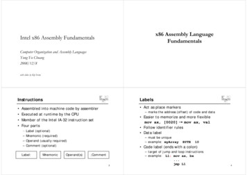
Parts List(Bill of Materials)Part#’s
Subassembly Drawing Subassembly: Two or more parts thatform a portion of an assembly. Can you think of some examples ofsubassemblies? A car differential A motorbike engine A compressor in an ACCopyright 2007 by K. PlantenbergRestricted use only
Definitions Does an assembly drawing normallyshow size?No. Its job is to locate parts. How do we show the size of anindividual part?A detail drawing is a drawing of an individualpart, which includes an orthographic projectionand dimensions.Copyright 2007 by K. PlantenbergRestricted use only
Working Drawing Package Working Drawing Package: A packet ofdrawings that gives the specificationsnecessary to manufacture a design. A typical working drawing packageA standard part sheetincludes;contains information about an assembly drawing,purchased items and willnot be discussed in this detailed drawings,course. and a standard partssheet.Copyright 2007 by K. PlantenbergRestricted use only
Drawing Order Drawings included in a working drawingpackage should be presented in thefollowing order. Assembly drawing (first sheet)Part Number 1Part Number 2.Standard parts sheet (last sheet)Copyright 2007 by K. PlantenbergRestricted use only
Assembly Drawings12.2) Views Used in AssemblyDrawingsCopyright 2007 by K. PlantenbergRestricted use only
Selecting Views Does an assembly drawing need aFRONT, TOP and RIGHT SIDE view?Sometimes We need as many views as it takes toidentify and locate each part. It may only take one view.Copyright 2007 by K. PlantenbergRestricted use only
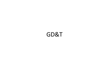
Needed 3 views tolocate all of the parts.
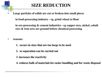
Needed only 1 view tolocate all of the parts.
Sectional Views Sectional views are used quite often whendrawing assemblies. Why?Assemblies often have parts fitting into oroverlapping other parts and we need to lookinside the assembly to see clearly.Copyright 2007 by K. PlantenbergRestricted use only
Section Hatch in Assemblies Section Hatch: Section hatch in adjacentparts are drawn in opposing directions. In the largest area, section hatch are drawnat 45 Next largest 135 (- 45o) Additional areas 30 and 60 Smaller areas The distance between thesection hatch may also be varied to furtherdistinguish between parts.Copyright 2007 by K. PlantenbergRestricted use only
Exercise 12-1Section hatch in assembliesCopyright 2007 by K. PlantenbergRestricted use only
Exercise 12-1 Draw the section hatch for the assemblyshown.Copyright 2007 by K. PlantenbergRestricted use only
Fill in the section hatch is the largest area.
Fill in the section hatch is the 2nd largest area.45o
Fill in the section hatch is the next largest area.-45o
Fill in the section hatch is the last area.-30o, smaller spacing
30o
Assembly Drawings12.3) Things to Include/Not IncludeCopyright 2007 by K. PlantenbergRestricted use only
Things to Include / Not Include When deciding what to include in anassembly drawing remember; The purpose of an assembly drawing is toshow how the individual parts fit together. It is not used as a manufacturing print.Copyright 2007 by K. PlantenbergRestricted use only
Things to Include / Not Include The assembly drawing should not lookoverly cluttered. Some lines that are necessary in a detaileddrawing may be left off the assemblydrawing to enhance clearness.Copyright 2007 by K. PlantenbergRestricted use only
Hidden Lines Do we include hidden lines?Usually They should be used wherever necessaryfor clearness. They should be left off when they impairclearness. When a section view is used, hidden linesshould not be used in that view.Copyright 2007 by K. PlantenbergRestricted use only
Dimensions Do we include dimensions?Usually not As a rule, dimensions are not given onassembly drawings. If dimensions are given, they are limited tosome function of the object as a whole.Copyright 2007 by K. PlantenbergRestricted use only
Identification Ballooning: A part is located andidentified, in an assembly drawing, byusing a circle containing the part numberand a leader line that points to thecorresponding part.Copyright 2007 by K. PlantenbergRestricted use only
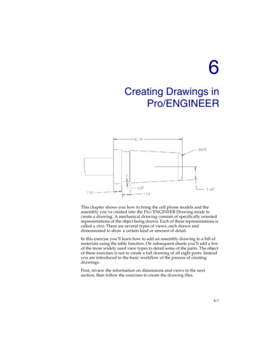
Leader lines point to thecorresponding part.Balloonscontainingpart numbers.
Balloons are placedin orderly horizontalor vertical rows.
The leader lines;- should not cross,- be as parallel as possible.
Parts List / Bill of Material The parts list is an itemized list of theparts that make up the assembledmachine.Copyright 2007 by K. PlantenbergRestricted use only
Parts List / Bill of Material Parts lists contain the part number, part name, the numberrequired and the material of the part.Copyright 2007 by K. PlantenbergRestricted use only
Parts List / Bill of Material Parts lists contain the Other information can be included, such as,stock sizes of materials and weights of theparts.Copyright 2007 by K. PlantenbergRestricted use only
Parts List / Bill of Material Parts are listed in order of their part#. Part#’s are usually assigned based on thesize or importance of the part.Copyright 2007 by K. PlantenbergRestricted use only
The parts list may beplaced in the upperright corner of thedrawing.- Part# 1 is at the top.
The parts list may beplaced in the lower rightcorner of the drawing.- Part# 1 is at the bottom.
Assembly Drawings12.4) Standard PartsCopyright 2007 by K. PlantenbergRestricted use only
Standard Parts Standard parts include any part thatcan be bought off the shelf. They do not need to be drawn. Purchasing information is given on thestandard parts sheet attached to the back ofthe working drawing package.Copyright 2007 by K. PlantenbergRestricted use only
Standard Parts Sheet ExamplePart NamePart NumberInformation needed to purchase the itemCopyright 2007 by K. PlantenbergRestricted use only
Standard Parts What type of information should beincluded?Copyright 2007 by K. PlantenbergRestricted use only
General Fastener Specifications Thread specification (for threaded fasteners) Name of fastener Head/Point style or shape (if applicable) Fastener length or size Fastener series Material Special requirements (coatings, finishes,specifications to meet) REQ’D (i.e. number required)Copyright 2007 by K. PlantenbergRestricted use only
Bolts and Nuts Specifications Thread specification contained in thethread note Style of head and name of the bolt or nut Length of bolt Material Special requirements (coatings, finishes,specifications to meet) REQ’D (i.e. number required)Copyright 2007 by K. PlantenbergRestricted use only
Exercise 12-2Working drawing packageCopyright 2007 by K. PlantenbergRestricted use only
Exercise 12-2 Draw an assemblydrawing of the Clampshown. Draw detaileddrawings of theindividual parts. Create a standardparts sheetCopyright 2007 by K. PlantenbergRestricted use only
Assembly Drawing
Part 1Drawing
Part 2 Drawing
Part 3 Drawing
Part 4Standard Part Sheet
Assembly DrawingsThe EndCopyright 2007 by K. PlantenbergRestricted use only
The parts list may be placed in the lower right corner of the drawing. - Part# 1 is at the bottom.