Transcription
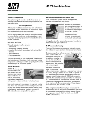
JM TPO Installation GuideSection 1 – IntroductionMechanically Fastened and Fully Adhered RoofsThis application guide describes standard procedures forinstalling Johns Manville (JM) TPO roofing systems and hasbeen prepared for:There are two basic types of JM TPO roofing systems:mechanically fastened and fully adhered.Mechanically fastened systems secure the membrane tothe roof with special fasteners, which vary depending onthe roof deck material.The Roofing MechanicJM recognizes that the success and long-term performanceof our roofing systems depend upon the personal skill, experience and knowledge of the roofing mechanic.JM TPO roofing systems offer important advantages for roofing crews. Roofing membranes can be installed year-roundwith proper roof deck preparation and some adjustments forweather conditions.How to Use This GuideThis guide is divided into five sections:1. Introduction2. Seaming and Fastening Methods3. Installing Mechanically Fastened and Fully Adhered RoofSystems4. Roof Penetrations5. Flashing InstallationThis guide is designed for your convenience. These step-bystep instructions and illustrations should answer your installation questions and help you maintain top-quality craftsmanshipwhen applying a JM TPO roofing system.JM TPO MembranesJM TPO Membranes aremanufactured to meet awide range of roof construction requirements.These membranes areused for mechanicallyattached and fully adheredroofing systems and are not intended for ballasted roofs.Each membrane sheet is marked along the edge with overlaplines. These lines indicate the minimum overlap required andthe area to be welded. Mechanically attached methods usingin-lap fastening require a larger overlap. A minimum 1½"(3.81 cm) welded seam is required for all systems.Several constructionvariations are possible withmechanically fastened roofs.In fully adhered roofing systems, the membrane is bonded tothe substrate with special adhesives.Roof Preparation (Re-Roofing)Proper roof deck preparation is essential to simplify installation and prevent future conditions that may lead to roof leaks.Carefully sweep all roof surfaces to remove all debris and dirt.Make sure the roofing areais completely smooth. Cut outlarge blisters on asphalt orcoal tar pitch roofs. Repairholes or cracks in concretegreater than ¼" (6.35 mm) widewith non-shrink grout.A slipsheet is often usedunder the membrane. It provides a smooth surface and acts as a separator layer betweenan existing, damaged roof and the new roof to be applied. JMTPO Membrane application may require the installation of aseparator material between the JM TPO Membrane and thesubstrate. This is most commonly achieved by the installationof a roof insulation board or an approved separator sheet. JMrecommends a slipsheet on all asphalt roofs and insulationfor all coal tar roofs. Remove loose nails and sharp ridges orburrs on concrete, if no insulation is used.When using mechanical fasteners, if you are unsure of thedeck condition, pull-out tests of the fasteners being used mustbe performed to confirm sufficient pull-out strength. Contactyour supervisor, who will obtain full details from the JMRoofing Services Group.
JM TPO Installation GuideEquipmentThe following equipment may be needed to install JM TPOroofing systems:Hammer drillElectric drillRivet gunSnipsGravel pusherHammerPull-out testerHand-held hot air welderBrooms (soft and stiff)Screw gunGlovesMeasuring tapeLadderPortable generatorRopeEye protectionWood sawMetal crimpersVise-grip pliersSolvent-resistant panScissorsWire brushChalk lineShovelPliersTongsGravel-moving equipmentLawn or linoleum rollerDrill bits (carbide, steel)Reciprocal sawGrounded extension cordsSeam probeFirst-aid kitUtility knifeScrewdriver setRubber malletRagsWriting/marking instrumentsT-squareRollers and brushesSection 2 – Seaming and Fastening MethodsThis section describes welding and fastening methods usedto install JM TPO roofing systems, including: installing hot airwelding membrane sections, using prefabricated JM TPOCoated Metal parts, seam testing, using fasteners to anchorthe roof to the roof deck, and adhesive application of themembrane.Seaming PrecautionsBefore welding, ensure area is clean and dry. Remove dirt orcontamination before welding by using low-sudsing soap andwater followed by JM Single Ply Membrane Cleaner or othermembrane cleaner. As a last resort, cut away the affectedsheet section and replace with new material.If JM TPO Membrane has been exposed for a period greaterthan 24 hours and/or compromised by dirt or debris, the areashall be cleaned with JM Single Ply Membrane Cleaner priorto welding to ensure full weld strength.Hot air welding equipment is required to make all field seams.Welding speeds will be slower in high humidity conditions orat low temperatures.General Suggestions to Avoid Problems in Cold Weather(Below 50 F [10 C])1. S tore all JM TPO materials in warm, dry areas to avoidcondensation problems that could affect weld quality. Storeaway from open sparks and flame sources.2. T ake at least twice the usual number of seam samplesto test for peel resistance, since the possibility of inferiorwelds is greater.3. Thoroughly dry all weld surfaces prior to welding.4. E xercise caution when walking on dew, frost, ice orsnow-covered roofs, since the membrane may be extremelyslippery.How Hot Air Welding WorksHot air welding works by applying very hot air to the membranesurfaces, softening and fusing the surfaces together, therebycreating a permanently fused, bonded sheet. One of the majoradvantages of hot air welding is the fact that the seam comesto full weld strength immediately.Reducing Stresses on Welded SeamsSeams must be loaded in shear and not in peel. A shear loadwould be in the plane (horizontal) of the roof membrane. Apeel load would be lifting the seam perpendicular to the roof.All roofs expand and contract during temperature changes.This can produce mechanical stress in the membrane. It isimportant to make welds that do not cause peel stresses tooccur.The correct and incorrect methods for welding at the roofsurface and side corners are described below.Correct: Weld the membrane to horizontal surface of theJM TPO-Coated Metal or membrane flashing, producing onlyhorizontal stress (shear stress) on the welded seam. This alsohelps transfer stress to the roof structure.Incorrect: The weld is subject to vertical stress (peel stress).Peel stresses weaken, and may eventually rupture the weldedseam.
JM TPO Installation GuideHand-Held Hot Air WeldingMembranes can be hot airwelded in many differentconditions, including coldweather. A hand-held hot airwelder is especially usefulwhen welding membrane sections at corners or on verticalsurfaces. Hand-held hot airwelders are also used to weldmembrane sections together or to weld membrane to JM TPOCoated Metal, which has factory-laminated JM TPO Membraneon its top side and a protective coating on the back.Machine Hot Air WeldingLarge robotic hot air welders are used for high-speedhot air welding of membraneseams. A variable speedcontrol for the electric motorlets you adjust the machine’stravel speed along the seam.Movement of the welder alongthe seam is determined by heat setting based on air temperature.To hot air weld, insert the nozzle fully into the 2" (5.08 cm)weld zone, and raise the back wheel to allow the machine toride on its two drive wheels. Dial in the desired temperatureand speed.To steer the tool along the seam, use the welder’s guidewheel. Watch the guide closely to make sure the machinestays on line.Surface irregularities can cause the pressure wheel to moveslightly away from the seam. If this happens, tap lightly on themachine’s upper handle to maintain travel in a straight line.Consult the hot air welder manufacturer for specific recommendations.As the hot air nozzle moves along the weld area, a wide drivewheel behind the nozzle applies immediate and uniform pressure to the heated area. The drive wheel presses the heatedseam area together. Check all machine hot-air-welded seamsfor voids, and patch with JM TPO Membrane and a hand-heldhot air welder. Seal all cut edges, including factory-cut edges,with JM TPO Edge Sealant. Always run several test weldswith the machine each time you begin welding and/or if themachine has been shut down for any length of time.With either method, perform a 4' or 5' (1.22 m or 1.52 m) testweld before beginning each day’s application and any timethe hot air welder has been turned off for any length of time.This checks peel strength, consistency, weld width, etc., andallows for welder adjustment.First, adjust the temperature of the hot air welder to producea shiny membrane surface without burning the membrane.Fully insert the tip of the hot air welder into the seam, moving it slowly backwards. As the membrane softens, press themembrane surfaces together with a silicone rubber roller fromthe inside edge to the outside edge of the seam. Take care toproduce a continuous weld with no air pockets.Repairing Scorched MembranesIf the membrane surface is overheated, a good weld cannotbe achieved. The burned or discolored membrane must bepatched.To repair a burned section, cut away the damaged material atleast 1" (2.54 cm) beyond the burned edges. Patches should becut to extend at least 3" (7.62 cm) beyond all damaged edges.Allow for a minimum 1½" (3.81 cm) weld width on all sides.Center the patch over the cut area and weld to the membrane,using normal welding procedures. Cut all patches in a squareor rectangular shape with round corners for a neat, finishedroof appearance.T-Joints, Testing and Sealing SeamsT-JointsThe t-joint occurs where three layers of membrane overlap.Voids may occur along the edge of the middle layer of membrane. To close the void, gently lift the upper membrane sheetand apply sufficient hot air to heat the membrane surfaces.Then, using the edge of a silicone rubber roller, roll and fusethe upper membrane surface into the lower membrane. Acrease developed along the intersection of the two surfacesindicates a proper weld.
JM TPO Installation GuideTesting SeamsJM TPO-Coated MetalHot air welded seams may be tested as soon as seams cool.After welding, carefully test every seam and t-joint along itsentire length. Do this by running a blunted scratch awl, cotterkey puller, or other round-tipped, blunted tool along the seamedge while applying firm, steady pressure. It is imperative toavoid scoring the membrane that has just been welded. Anypenetration of the probe into the seam indicates a void in theweld, which must be patched. Continuous seam probing willtend to sharpen the tip of the probe, so it is important to bluntthe tip of the probe regularly. JM recommends patching allt-joints — to include base flashing — using a 7" (17.78 cm)rounded piece of reinforced field membrane or JM TPOT-Joint Patch.JM TPO-Coated Metal isa special flashing materialused to fasten some JM TPOMembranes at roof edges(perimeters), walls, decksand around penetrations. It issupplied in large, galvanizedsheets with JM TPO NonReinforced Membrane material laminated to one side.The roof membrane is welded to this surface. The other side isgalvanized metal.Test all welded seams forintegrity and continuity beforethe end of each work day.In addition to probing, takeseam samples to verify seamquality as necessary.JM TPO-Coated Metal Flashing is formed off site by theroofing contractor, to the shapes required for attaching themembrane. Preforming numerous perimeter flashing sectionsin the same shape is easily and accurately done in the sheetmetal shop. Prefabrication reduces installation time. Specialparts such as scuppers, however, are formed on the job tomatch the opening size and save time.JM Fasteners and PlatesCut the samples across theseam 6" (15.24 cm) on eachside of the seam and 2" (5.08 cm) wide. Peel these samplesby hand to test seam strength. Good seams will be virtuallyimpossible to peel and should delaminate the JM TPO filmfrom the reinforcing scrim. Cut and test a minimum of threeseam samples each day — in the morning, at noon and atday’s end. Take additional test cuts when weather conditionschange or after work interruptions when the automatic hot airwelder has been shut off.Use appropriate fastenersand plates on mechanicallyfastened roofs to fasten themembrane and/or insulation tothe roof deck. Special screwsand fasteners simplify attachment of roof layers to wood,steel, concrete, lightweight orother decks.Sealing SeamsThe most common method of installing a JM TPO mechanicallyfastened roofing system is the in-lap method, where the membrane overlap covers and protects the installed fasteners.Seal all cut seam edges with JM TPO Edge Sealant aftertesting and repairing. This prevents water from entering thewelded area through wicking or capillary action. Weld andseal seams at all cut edges onthe same day. Clean and dryany edges that stand overnight to ensure good sealantadhesion. Apply sealant witha squeeze bottle. Draw the tipsmoothly along the cut edgeof the membrane to produce auniform 1 8" (3.18 mm) bead.JM High Load and Extra High Load Fasteners and Platesare used to attach the roof system to steel and wood decks.Special fasteners are used for lightweight insulating concreteand concrete decks.
JM TPO Installation GuideJM supplies many fastenersfor mechanically fastenedroofs. There are several keyrules to follow when installinga mechanically fastened roof:1. Use appropriate fastenertype for substrate.2. Securely anchor fastenersto roof deck.3. Flatly seat and secureplates on substrate.4. Do not tighten fastener/plate assembly excessively, whichcauses depression of insulation.5. Achieve minimum thread penetration of ¾" (1.91 cm)through metal decks, 1" (2.54 cm) into wood decks and 1"(2.54 cm) into concrete decks with special spikes. Plywoodand OSB decks require a minimum of ¼" (6.35 mm) penetration through the bottom of the deck.6. Fasteners must go through the top flange on metal decks.Membrane AdhesivesJM TPO Membrane Adhesives (Solvent-Based and WaterBased)JM TPO Membrane Adhesive (Solvent-Based) is designedfor bonding JM TPO Membrane to metal, wood, concreteand certain roof insulations and should be used to adherewall flashings or other vertical surfaces. The solvent-basedadhesive is easily spread, has good initial tack and dries to anelastomeric bond.JM TPO Membrane Adhesive (Water-Based) is a water-based,polymeric, low-VOC adhesive for bonding JM TPO Membraneto horizontal surfaces. This product conforms to many air qualityand VOC requirements and has excellent tack and green strength.JM TPO Membrane Adhesive (Low VOC) is a synthetic, rubberbased, two-sided, low-VOC adhesive for bonding JM TPOMembrane to horizontal and vertical surfaces. This productconforms to many air quality and VOC requirements.For additional product-specific information, refer to the JMTPO Membrane Adhesive data sheets for solvent-based andwater-based products.Section 3 – Installing Mechanically Fastened and FullyAdhered Roof SystemsThis section describes the procedures and materials used toinstall mechanically fastened and fully adhered JM TPO roofs.Included are: flashing installation, membrane installation,membrane fastening procedures for mechanically fastenedroofs and adhering roof membranes.Installation PreparationNailersAfter properly preparing the roof deck, install wood nailerswhen required. Place nailers on the perimeter of the roof,along the top of parapet walls and, where required, aroundroof penetrations and along roof expansion joints. Set theheight of the nailers flush with the roof insulation.Space fasteners for wood nailers a maximum of 24" (60.96 cm)o.c. with at least three fasteners per nailer, depending on nailerlength. Each fastener must resist a minimum pull-out force of200 lb/ft (298 kg/m) in any direction.JM TPO-Coated Metal Flashings are fastened to wood nailers.When using membrane flashings, fasten the field sheet to thedeck with a fastener/plate system as shown in Detail TB-25.JM TPO-Coated Metal FlashingPreformed JM TPO-CoatedMetal Flashing is fastenedaround the roof perimeter(edge and base flashings)and roof penetrations.Welding the membraneto JM TPO-Coated MetalFlashings at these points provides a watertight seal.JM TPO-Coated Metal Flashing is manufactured in 10' (3.05 m)lengths. Leave a 3 8" to 1 2" (9.53 mm to 1.27 cm) maximum gapbetween each length to allow for thermal expansion. Aluminumtape should be applied over all joints in JM TPO-Coated Metalprior to heat welding the joint covers and membrane in place.JM TPO-Coated Metal Flashing can be used as an asphaltseparator in lieu of plywood or galvanized metal.
JM TPO Installation GuideThe following are instructions for installing JM TPO-CoatedMetal base flashing, wall fastening strips and gravel stops.Base Flashing with JM TPO-Coated MetalSet the base flashing width along the horizontal roof surface(flange) at least 3½" (8.89 cm) to allow for welding and caulking with JM TPO Edge Sealant. Flashing must extend a minimum of 8" (20.32 cm) up vertical wall surfaces.Fasten base flashing to nailers per the job specifications, butas a minimum, using galvanized roofing nails, spaced a maximum of 6" (15.24 cm) o.c. to resist a minimum pull-out force of200 lb/ft (298 kg/m). Nail heads should be at least 3 8" (9.53 mm) indiameter, penetrating into the nailer at least 3 4" (1.91 cm).You may fasten JM TPO-Coated Metal base flashing directlyto the parapet wall under some conditions. Consult job specifications. Fasteners must provide a minimum pull-out force of200 lb/ft (298 kg/m), placed at a maximum height of 2" (5.08 cm)above the top surface of the JM TPO Membrane.Fasten JM TPO-Coated Metal base flashing to concrete withconcrete fasteners. Space fasteners per the job specifications, but not greater than 12" (30.48 cm) o.c. and drive atleast 1" (2.54 cm) into concrete to obtain the required pulloutstrength. JM TPO-Coated Metal base flashing can also be fastened to hollow block (cinder block) walls with the appropriatefasteners. Consult JM for more details.JM TPO-Coated Metal Flashing can be used as an asphaltseparator in lieu of plywood or galvanized metal.Wall Flashing with JM TPO-Coated MetalJM TPO-Coated Metal base flashing serves as a roof termination on roofs with low parapet walls. A metal coping overlapsthe JM TPO-Coated Metal base flashing and serves as acounterflashing on walls which are 8" (20.32 cm) or less.Higher walls are sealed with JM TPO Membrane Flashing. See“Membrane Flashing” section for application of fully adheredand mechanically attached flashings.Gravel StopsThe top of the gravel stopmust be at least 1½" (3.81 cm)above the nailer height. Thismay vary, depending on roofconditions. The bottom edgeof the flashing should extendat least 1" (2.54 cm) below thenailer on the vertical fasciasurface.If the vertical gravel stop face exceeds 4" (10.16 cm), fastenper the job specifications, but not less than a 20-gauge to24-gauge (0.91 mm to 0.61 mm), continuous galvanized steelclip on the fascia.Fasten continuous steel cleats per the job specifications, butnot less than two roofing nails, between flashing lengths. Thisprovides a rigid support for the gravel stop and helps align thesection. Use lengths of gravel stop to quickly position eachcleat. Fasten the gravel stop to the wood nailer with roofingnails spaced 6" (15.24 cm) o.c. and staggered. Leave a 3 8" to 1 2"(9.53 mm to 1.27 cm) gap for expansion between gravel stoplengths. Apply aluminum tape to the joint prior to heat weldingthe joint covers and membrane in place.Membrane FlashingsInstall all membrane flashingsat the same time as the roofmembrane. Do not use temporary flashings. If water penetrates the flashings, immediately replace all affectedmaterials.Use only JM TPO fully adhered or mechanically attachedflashings or prefabricated flashings, depending on job circumstances. Secure the mechanically attached flashings to theparapet wall at a maximum vertical distance of 18" (45.72 cm)o.c., and horizontally to the parapet at maximum spacing of 12"(30.48 cm) o.c. Secure adhered flashings to the parapet wallat 36" (91.44 cm) vertical intervals. All adhered surfaces mustbe compatible with JM TPO roofing membranes. If existingasphalt flashing remains, then 15 32" (1.19 cm) thick plywood,9 16" (1.43 cm) OSB, 26-gauge (0.45 mm) galvanized metal (ifusing adhered flashings), or 9 oz./yd2 (0.31 kg/m2) polyesterfleece must be secured to the asphaltic surface as a barrierbefore applying JM TPO Membrane Flashings. Paper slipsheets are not acceptable for use as asphalt barriers. Applyadhesive as noted in Section 3, “Fully Adhered Systems.”Do not apply adhesive to any flashing areas that will bewelded.Extend all flashings a minimum of 8" (20.32 cm) above the rooflevel. Contact the JM Roofing Services Group for recommendations if this cannot be done. Terminate all JM TPO MembraneFlashings per the applicable detail.
JM TPO Installation GuideRoof Substrate MaterialsCoal Tar PitchVapor RetardersCoal tar pitch roofs give off noxious fumes and vapors whichcan affect JM TPO roofing membranes. You must separatecoal tar pitch roofs from the JM TPO Membrane in the following manner:Vapor retarders prevent moisture or condensation from entering the building, or passing from the building into the roof system. To provide an effective shield against water vapor, sealoff all vapor retarders at roof edges and penetrations.Air BarriersAir barriers should be considered on jobs where high internalair pressure exists, such as airport hangars or distributionwarehouses with many outside openings (such as loadingdocks), outdoor amphitheaters, etc.InsulationInsulation must be independently fastened to the roof deck inmechanically attached and adhered systems. Adhering certain insulations in hot asphalt or cold adhesives is sometimesacceptable for adhered systems. For specific requirements,contact the JM Roofing Services Group.Always cut insulation to fit closely around all roof penetrations. Around drains, taper insulation a minimum of 36" x 36"(91.44 cm x 91.44 cm) for proper drainage.Apply rigid insulation directly over fluted steel decks to providesmooth, continuous membrane support. Insulation should beinstalled with long edges parallel to the direction of the deckand supported by the deck flange. When butting insulation layers, do not allow the edge of either board to overlap an openflute. Cut the insulation so the edge of the board is about atthe center of, and supported by, the top flange.Slipsheets Place insulation with a minimum R-value of 10.0 (hr ft2 F)/Btu [1.76 m2 C/W] and a minimum thickness of 1½"(3.81 cm) over the existing roof, with the joints of theinsulation butted together at all four sides.Installing MembranesUnroll the JM TPO Membrane and position without stretching. Allow the membrane to relax for at least 15 minutes whenthe temperature is above 60 F (16 C), or 30 minutes when thetemperature is below 60 F (16 C) prior to installation. Inspect forany damaged membrane. Remove sections of the membranethat are creased or damaged.Install all roof deck materials (vapor retarders, insulation andslipsheets) in complete sections, and cover with the membraneimmediately to produce weathertight sections each day.Phased construction is not permitted.For mechanically attached systems on steel decks, the membrane sheets must be applied perpendicular to the ribs (flutes)of the deck. This method offers two advantages. First, mostroofs are pitched to drain along the roof’s length. Many roofsdrain from each end to the middle. In this case, the installationis started at the wall edge, and the membrane is welded andsealed immediately against water infiltration. It also requiresless work to seal the shorter edge of the roof with a watercutoff at the end of the work day. And you will save money byremoving and discarding less cut-off material.A slipsheet is often used under the membrane on mechanicallyfastened roofs. It provides a smooth surface over which themembrane can freely expand or contract when temperaturevariations cause changes in the roof structure.Welding Membranes to Roof EdgesThe slipsheet is loosely laid and usually overlapped, depending on the slipsheet selected. It should be neatly cut to fitclosely against roof edges and around penetrations. Anapproved slipsheet must be used between the JM TPOMembrane and any polystyrene insulation product.Mechanically Fastened SystemsThe JM TPO- Coated Metal Edge is installed and is strippedinto the field sheet with a detail strip.To prevent wind uplift and secure the membrane on mechanically attached roofs, fasten the membrane to the roof deck withmetal plates and acceptable fasteners.
JM TPO Installation GuideCorners and PerimetersRefer to the local code requirements, project specifications orFM Global requirements when determining fastener rates. Therequirements to calculate perimeter areas are as follows:1. 40% of the height or 10% of the lesser plan dimension,whichever is less (minimum 3' [91.44 cm]).2. For mechanically fastened systems, only perimeter rollsmay be used in these areas. The width of the perimeterrolls should be no greater than 60% of the width of the fieldsheets in the perimeters, and no greater than 40% of thewidth in the corners.Corner AreasAll corners shall be the intersections of the perimeter areas.Refer to the local code requirements, project specifications orFM Global requirements when determining corner layouts forperimeter sheets. Typically, one of the following layouts is usedin the corners:1. The perimeter rolls should be fastened all the way into thecorner. The other perimeter sheets are fastened up to thepreviously installed perimeter sheets, and then the fastenerrows are continued to the corner through the top of thepreviously installed sheets. Install a cover strip of reinforcedmembrane extending 2" (5.08 cm) on each side over thefasteners for a watertight seal.2. The perimeter rolls should be run perpendicular to the flutesin steel deck applications. Additional fasteners should beinstalled in rows that are no greater than 40% of the widthof the field sheets. These fastener rows should then bestripped in with reinforced JM TPO Membrane.Section 2 describes the plates and methods used tomechanically fasten JM TPO roofs. Following are step-by-stepprocedures for in-lap fastening.The In-Lap Method1. Roll out one roll of membrane over the slipsheet(if required) or acceptableinsulation board. Let itrelax 15 to 30 minutes or asneeded to compensate forany residual roll tension.2. Secure the plate along the edge of the membrane, maintaining at least a ½" (1.27 cm) distance from the edge of the plate tothe outer edge of the roll. Fastener and plate spacing is perFM Global requirements and/or job specifications.3. Tightly screw down the plates (do not overdrive the fastener)using an appropriate screw gun unit with adjustable torqueclutch. Make certain to drive the fastener perpendicular tothe surface of the substrate and to properly penetrate thedeck surface. On steel decks, the screws must be fastenedinto the top flanges of the deck.4. After securing the edge of the first membrane roll, unrollthe next adjacent roll of membrane. Position this roll sothat its common edge fully overlaps the row of plates andfasteners just installed. Maintain a minimum overlap of 6"(15.24 cm) (depending on plate size) to cover the plates, andleave the required 1½" (3.81 cm) minimum for the seam weld.5. Weld the overlap seam. Apply a bead of liquid JM TPOEdge Sealant along all cut edges of the overlap.Fully Adhered SystemsAll membranes and substrates to be adhered must beapproved by Johns Manville. Both surfaces must be clean,smooth, dry, compatible and free of contaminants andgrease/oil. All fasteners, if required, must be properly seatedand plates flush, leaving an acceptable surface to receiveadhesive.Unroll the membrane and allow it to relax at least 15 minutesbefore applying adhesive, longer time is necessary in colderweather.Position the membrane with a 2" (5.08 cm) overlap betweensheets. Fold membrane back one-half of the length of the firstsheet’s length to expose its bottom side.Make sure adhesive container is sealed. Turn upside downand wait a minimum of five minutes. Turn container right-sideup. Carefully open and vigorously stir until adhesive is a uniform color and all solids are dispersed, with NO SWIRLS.Saturate roller by dipping into can. Roll adhesive onto substrate and membrane for smooth-backed membrane, and substrate only for fleece-backed membrane.For solvent-based adhesives, the appearance of a spider webeffect will occur with stringers off the roller when the rollerneeds to be redipped into the adhesive. It will also be hard topush the roller.Follow directions in this section for specific adhesive andmembrane type (i.e., smooth-backed or fleece-backed) asdirected for proper applications.
JM TPO Installation GuideWhen adhesive is ready, carefully roll the membrane into thesubstrate, avoiding wrinkles. Apply even pressure with a lawnor linoleum roller (minimum 75 lb [34 kg]) to ensure good contact between the membrane and substrate.Do not apply adhesive in the seam area; seams are to remainclean and dry. Avoid puddling of adhesive. With adhesives,more is not necessarily better. “Over-coating” adhesives willlead to poor adhesion.Do not use in direct contact with polystyrene foam.Adhesive coverage, open time and dry time rates can varydramatically depending on the particular substrate and environmental conditions. Coverage rate charts, stated herein, areapproximate only. If FM Global or UL approval is required,please consult the specific RoofNavSM or UL certificationdirectory for specific application rates.Invinsa ENRGY 3 DensDeck N/AN/AWB/SBWB/SBP/AWB/SBWB/SBJM TPOFleece-BackedWBWBWBWBP/AWBWBWood FiberConcreteJM TPOGypsum FiberRoof BoardLightweightConcreteSECUROCK Apply water-
How to Use This Guide This guide is divided into five sections: 1. Introduction 2. Seaming and Fastening Methods 3. Installing Mechanically Fastened and Fully Adhered Roof Systems 4. Roof Penetrations 5. Flashing Installation This guide is designed for your convenience. These step-by-step instructions and illustrations should answer your installa-