Transcription
SAND2017-0455 OMELCOR ComputerCode ManualsVol. 1: Primer and Users’ GuideVersion 2.2.9541 2017Date Published: January 2017Prepared byL.L. Humphries, B.A. Beeny, F. Gelbard, D.L. Louie, J. PhillipsSandia National LaboratoriesAlbuquerque, NM 87185-0748Operated for the U.S. Department of EnergyH. Esmaili, Nuclear Regulatory Commission Project ManagerPrepared for Division of Systems AnalysisOffice of Nuclear Regulatory ResearchU.S. Nuclear Regulatory CommissionWashington, DC 20555-0001
SAND2017-0455 O- ii -
AbstractMELCOR is a fully integrated, engineering-level computer code that models theprogression of severe accidents in light water reactor nuclear power plants. MELCOR isbeing developed at Sandia National Laboratories for the U.S. Nuclear RegulatoryCommission as a second-generation plant risk assessment tool and the successor tothe Source Term Code Package. A broad spectrum of severe accident phenomena inboth boiling and pressurized water reactors is treated in MELCOR in a unifiedframework. These include thermal-hydraulic response in the reactor coolant system,reactor cavity, containment, and confinement buildings; core heatup, degradation, andrelocation; core-concrete attack; hydrogen production, transport, and combustion;fission product release and transport behavior. Current uses of MELCOR includeestimation of severe accident source terms and their sensitivities and uncertainties in avariety of applications.This publication of the MELCOR computer code manuals corresponds to MELCOR 2.1.Volume 1 contains a primer that describes MELCOR’s phenomenological scope,organization (by package), and documentation. The remainder of Volume 1 containsthe MELCOR User’s Guides, which provide the input instructions and guidelines foreach package. Volume 2 contains the MELCOR Reference Manuals, which describethe phenomenological models that have been implemented in each package. Volume 3of this publication presents a portfolio of test and sample problems consisting of bothanalyses of experiments and of full plant problems.- iii -SAND2017-0455 O
SAND2017-0455 O- iv -
ContentsVolume 1: Primer and Users’ GuideThe following chapters are found in Volume 1 of this code manual set.MELCOR PrimerExecutive (EXEC) Package Users’ GuideAccumulator (ACC) Package Users’ GuideBurn (BUR) Package Users’ GuideCavity (CAV) Package Users’ GuideCondenser (CND) Package Users’ GuideControl Function (CF) Package Users’ GuideCore (COR) Package Users’ GuideControl Volume Hydrodynamics (CVH) Package Users’ GuideDecay Heat (DCH) Package Users’ GuideExternal Data File (EDF) Package Users’ GuideFan Cooler (FCL) Package Users’ GuideFuel Dispersal (FDI) Package Users’ GuideFlow Path (FL) Package Users’ GuideHeat Structures (HS) Package Users’ GuideLower Head Containment (LHC) Package Users’ GuideMaterial Properties (MP) Package Users’ GuideNonCondensible Gas (NCG) Package Users’ GuidePassive Autocatalytic Hydrogen Recombiner (PAR) Package Users’ GuideRadioNuclide (RN) Package Users’ GuideContainment Sprays (SPR) Package Users’ GuideTabular Function (TF) Package Users’ GuideTransfer Process (TP) Package Users’ Guide-v-SAND2017-0455 O
SAND2017-0455 O- vi -
Executive SummaryMELCOR is a fully integrated, engineering-level computer code whose primary purposeis to model the progression of accidents in light water reactor nuclear power plants. Abroad spectrum of severe accident phenomena in both boiling and pressurized waterreactors is treated in MELCOR in a unified framework. Current uses of MELCORinclude estimation of fission product source terms and their sensitivities anduncertainties in a variety of applications.The MELCOR code is composed of an executive driver and a number of majormodules, or packages, that together model the major systems of a reactor plant andtheir generally coupled interactions. Reactor plant systems and their response to offnormal or accident conditions include: thermal-hydraulic response of the primary reactor coolant system, the reactorcavity, the containment, and the confinement buildings, core uncovering (loss of coolant), fuel heatup, cladding oxidation, fueldegradation (loss of rod geometry), and core material melting and relocation, heatup of reactor vessel lower head from relocated fuel materials and thethermal and mechanical loading and failure of the vessel lower head, andtransfer of core materials to the reactor vessel cavity, core-concrete attack and ensuing aerosol generation, in-vessel and ex-vessel hydrogen production, transport, and combustion, fission product release (aerosol and vapor), transport, and deposition, behavior of radioactive aerosols in the reactor containment building, includingscrubbing in water pools, and aerosol mechanics in the containmentatmosphere such as particle agglomeration and gravitational settling, and, impact of engineered safety features on thermal-hydraulic and radionuclidebehavior.The various code packages have been written using a carefully designed modularstructure with well-defined interfaces between them. This allows the exchange ofcomplete and consistent information among them so that all phenomena are explicitlycoupled at every step. The structure also facilitates maintenance and upgrading of thecode.Initially, the MELCOR code was envisioned as being predominantly parametric withrespect to modeling complicated physical processes (in the interest of quick codeexecution time and a general lack of understanding of reactor accident physics).However, over the years as phenomenological uncertainties have been reduced anduser expectations and demands from MELCOR have increased, the modelsimplemented into MELCOR have become increasingly best estimate in nature. Theincreased speed (and decreased cost) of modern computers (including PCs) has eased- vii -SAND2017-0455 O
many of the perceived constraints on MELCOR code development. Today, mostMELCOR models are mechanistic, with capabilities approaching those of the mostdetailed codes of a few years ago. The use of models that are strictly parametric islimited, in general, to areas of high phenomenological uncertainty where there is noconsensus concerning an acceptable mechanistic approach.Current uses of MELCOR often include uncertainty analyses and sensitivity studies. Tofacilitate these uses, many of the mechanistic models have been coded with optionaladjustable parameters. This does not affect the mechanistic nature of the modeling, butit does allow the analyst to easily address questions of how particular modelingparameters affect the course of a calculated transient. Parameters of this type, as wellas other numerical parameters such as convergence criteria and iteration limits, arecoded in MELCOR as sensitivity coefficients, which may be modified through optionalcode input.MELCOR modeling is general and flexible, making use of a "control volume" approachin describing the plant system. No specific nodalization of a system is forced on theuser, which allows a choice of the degree of detail appropriate to the task at hand.Reactor-specific geometry is imposed only in modeling the reactor core. Even here, onebasic model suffices for representing either a boiling water reactor (BWR) or apressurized water reactor (PWR) core, and a wide range of levels of modeling detail ispossible. For example, MELCOR has been successfully used to model East Europeanreactor designs such as the Russian VVER and RMBK-reactor classes.The MELCOR 2.1 code manuals are contained in three volumes. Volume 1 contains aprimer that describes MELCOR’s phenomenological scope, organization (by package),and documentation. The remainder of Volume 1 contains the MELCOR User’s Guides,which provide the input instructions and guidelines for each package. Volume 2contains the MELCOR Reference Manuals, which describe the phenomenologicalmodels that have been implemented in each package. Volume 3 contains a portfolio ofsample demonstration problems. These problems are a combination of experimentanalyses, which illustrate code model performance against data, and full plant analysesshowing MELCOR’s performance on larger realistic problems.SAND2017-0455 O- viii -
AcknowledgmentsThe authors preparing this document would like to acknowledge the contributions madeby the following MELCOR project members since the release of the previous MELCORUsers’ Guide – SAND2016-6691:Larry L. HumphriesCode Development and Testing and Project ManagerSNLRandall K. ColeCode Development and TestingSNLMichael F. YoungCode Development and TestingSNLRodney C. SchmidtCode Development and TestingSNLJohn ReynoldsConfiguration ManagementSNLChun FuTestingSNLRandall O. GaunttTechnical ManagerSNL- ix -SAND2017-0455 O
SAND2017-0455 O-x-
MELCOR PrimerThe MELCOR code models a wide range of physical phenomena including thermalhydraulics; heat transfer; aerosol physics; the heatup, degradation, and relocation ofreactor cores; ex-vessel debris behavior; and fission product release and transport. It wasdeveloped to model the progression of accidents in light water nuclear power plants, butmany other applications are also possible.This primer provides a starting point in understanding MELCOR and learning how to applyit. It includes an overview of the file structure, user input conventions, and the mechanics ofrunning the code, as well as general descriptions of the phenomena modeled and of thesupporting properties and utility modules that are included in MELCOR.The information contained here is, by itself, far from sufficient to allow a new user tosuccessfully run MELCOR. However, it provides an essential overview and introduction tothe balance of the code documentation.MELCOR Primer-UG-1SAND2017-0455 O
MELCOR PrimerContents1INTRODUCTION . 32GENERAL PROGRAM AND FILE RELATIONS . 33LICENSING . 64MELCOR PACKAGES . 75GETTING STARTED . 10REFERENCES. 12SAND2017-0455 OMELCOR Primer-UG-2
MELCOR Primer1 IntroductionMELCOR is a fully integrated, relatively fast-running code that models the progression ofaccidents in light water reactor nuclear power plants. An entire spectrum of accidentphenomena is modeled in MELCOR. Characteristics of accident progression that can betreated with MELCOR include the thermal-hydraulic response in the reactor coolant system,reactor cavity, containment, and confinement buildings; core heatup and degradation;radionuclide release and transport; hydrogen production, transport, and combustion; meltejection phenomena; core-concrete attack; heat structure response; and the impact ofengineered safety features on thermal-hydraulic and radionuclide behavior.MELCOR has been designed to facilitate sensitivity and uncertainty analyses through theuse of sensitivity coefficients. Many parameters in correlations, which are hardwiredconstants in most codes, are implemented as sensitivity coefficients in MELCOR.Sensitivity coefficients can be changed by the user through input as discussed in theMELCOR/MELGEN Users’ Guide and in the Users’ Guides for each package. For example,the coefficients in a heat transfer correlation are usually assumed to be constant. However,in MELCOR the constants are coded as sensitivity coefficients that can be changed by theuser to determine the sensitivity of the results to the heat transfer correlation.The documentation of MELCOR is divided into three areas:(1)Users’ guides and(2)Reference manuals, generally written for each package in MELCOR.(3)Sample calculations.The various packages are listed later in this document. Input instructions and guidelines foreach package are given in the appropriate Users’ Guide. The phenomenological modelsthat have been implemented are documented in each package’s reference manual. Sampleproblems have been provided to give the user some guidance in developing models. Thepurpose of this primer is to guide the uninitiated user through the extensive MELCORdocuments.2 General Program and File RelationsMELCOR is executed in two parts. The first part is called MELGEN, in which the majority ofinput is specified, processed, and checked. When the input checks are satisfied, a RestartFile is written for the initial conditions of the calculation. The second part of MELCOR is theMELCOR program itself, which advances the problem through time based on the input toMELGEN and any MELCOR input. Graphics post processing is provided by PTFREAD, anEXCEL add-in utility.The files used by MELGEN and MELCOR are:MELCOR Primer-UG-3SAND2017-0455 O
MELCOR PrimerUser InputThe MELGEN User Input File contains the majority of the userinput defining the problem for MELCOR. MELGEN processesand checks this input and creates a Restart File for MELCOR.MELCOR relies on the Restart File for the bulk of its input.Some timestep, problem duration, and edit information issupplied via the MELCOR User Input File. The input data forMELGEN and MELCOR can be combined into a singlecomputer file.OutputBoth MELGEN and MELCOR generate printed output, all ofwhich is written to their respective normal Output Files. Selectedinformation is written also to the Diagnostic, Message, andTerminal Files, as discussed below, for the convenience of theuser. The Output Files echo the User Input Files with a completelisting of all user input. The MELGEN Output File gives a fulllisting of all processed data, including time-independent data.The MELCOR Output File contains successive edits of timedependent data written to it at time intervals determined by theuser.PlotThe values of all MELCOR plot variables are written to thebinary Plot File at time intervals determined by the user. ThePlot File can be read by PTFREAD or other graphics postprocessing programs.RestartThe MELCOR database, containing all the necessary data torestart MELCOR, is written to the Restart File at time intervalsdetermined by the user. MELGEN generates the initial RestartFile containing the initial conditions of the problem set up byuser input. MELCOR extends this file as required.MessageSpecial messages are written to the Message File. This file iswritten only by MELCOR and contains the occurrence time ofsignificant events such as vessel bottom head failure, meltejection, hydrogen burns, etc. As a user convenience, theMessage File is copied to the end of the Output File at executiontermination.DiagnosticThe Diagnostic File contains certain diagnostic messagesgenerated by MELGEN and MELCOR, including errormessages and warnings that are useful to the user. As a userconvenience, the Diagnostic File is copied to the end of theOutput File when there is an abnormal calculation abort.SAND2017-0455 OMELCOR Primer-UG-4
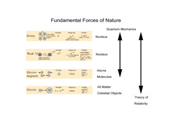
MELCOR PrimerExtended DiagnosticThe Extended Diagnostic File contains more completediagnostic information than the Diagnostic File but retains onlythe latest messages. This file is most useful to the developers totrace code problems that the user cannot control.TerminalThe Terminal File (or Batch Job “Log” File) contains directterminal output from MELCOR giving a brief summary of thecourse of the calculation. In addition to special messages, theproblem time, timestep, and CPU time are written to this file asrequested by the user.StopThe user may create this file at any time during a batchMELCOR execution. If this file is present, the MELCORcalculation is terminated and data are written to the Output, Plot,and Restart Files for the last cycle.MailThe user may create this file at any time during a batchMELCOR execution. If this file is present, MELCOR will create ashort summary of the state of the calculation and mail it to theuser. The purpose of this feature is to give the user informedcontrol over batch jobs.The controls for these files are found in the Executive (EXEC) Package Users’ Guide. Therelationship between MELGEN, MELCOR, and PTFREAD as well as the above files isshown in Figure 2.1. MACCS [1], also shown in Figure 2.1, is a program to determine offsite consequences of fission product releases to the environment.The Diagnostic and Message Files should be closely examined following every run. TheDiagnostic File contains error messages or other information that may indicate a problemwith the initial conditions specified in MELGEN or with the MELCOR calculation. The usershould examine the Diagnostic File carefully after every run for indications of problems inthe results. The Message File contains information concerning the timing of importantevents such as combustion of gases, failure of the lower head, and others. This fileprovides a summary of the events in the calculation without having to look through theentire output file. All the messages in these two files (Message and Diagnostic) are alsoincluded in the Output file. The Message File also contains information about the RestartFile.MELCOR Primer-UG-5SAND2017-0455 O
MELCOR PrimerFigure 2.1 MELCOR Code and File RelationsThe extended Diagnostic File contains more complete information useful to the developerwhen a calculation aborts. All diagnostic messages are saved in this file. Periodically, theearlier half of these messages is discarded to limit the file size.3 LicensingIn MELCOR 2.1, licensing has been incorporated to protect the MELCOR and MELGENexecutables from unauthorized changes. Each time the executables are run an attempt ismade to open the Product.key file. If the executable does not find this file an error will bedisplayed and MELCOR will not run.Follow these instructions to license MELCOR for a specific machine:(1)Download the license.zip file from http://melcor.sandia.gov.Note: Each time a license is downloaded, the MELCOR database is annotated withinformation that helps the NRC to track MELCOR usage statistics. The license is alsoencoded with information that can be used to identify its recipient. Do not transferlicense files to anyone else.(2)Extract the license.zip file into any directory on your hard disk.SAND2017-0455 OMELCOR Primer-UG-6
MELCOR Primer(3)Browse to that directory and double-click on the registration script:run register.bat (Windows) or run register.bash (UNIX/Linux). The script calls theregister.exe executable and pauses when it completes. The script allows you toview the registration results—if you’re working at the command-line you canchoose to launch the registration executable directly.(4)The message “Product key has been successfully bound to this computer” will bedisplayed if the registration was successful. If any other message is displayed, theaction is unsuccessful and MELCOR will not run. In this case, contact a memberof the MELCOR team for help.Note: License keys are time-dependent. If not registered on a computer within a shorttimeframe (usually a day or two), the registration process outlined here will not work.If your license key file expires before you register it, you’ll need to retrieve a newlicense archive file and start over.(5)Copy calu dll.dll and Product.key to each directory containing the MELCOR andMELGEN executables. The MELCOR and MELGEN executables will not run inany folder that does not contain these files.(6)For safety purposes, delete files run register.bat (or run register.bash),register.exe and license.zip. These files are not needed after the key file isregistered. Running them multiple times against the same key will preventMELCOR from running.To license MELCOR for multiple computers, one license file is all that is needed. Simplyobtain one license archive, copy it to each computer and go through steps 2 through 6 foreach computer.4 MELCOR PackagesMELCOR is composed of a number of different packages, each of which models a differentportion of the accident phenomenology or program control. For example, the ControlVolume Hydrodynamics (CVH) package calculates the thermal-hydraulics of controlvolumes, and the Core (COR) package evaluates the core behavior. Each of the packagesin MELCOR is listed below with a brief description:BURBurn (Combustion) of Gases. Compares conditions withincontrol volumes against criteria for deflagrations anddetonations. Initiates and propagates deflagrations involvinghydrogen and carbon monoxide. Calculates burn completenessand flame speed.CAVCore-concrete Interactions. Models the attack on the basematconcrete by hot core materials. CORCON-MOD3 with enhancedsensitivity analysis and multi-cavity capabilities.MELCOR Primer-UG-7SAND2017-0455 O
MELCOR PrimerCFControl Functions. Evaluates user-specified control functionsand applies them to define or control various aspects of thecomputation such as opening and closing of valves; controllingplot, edit, and restart frequencies; defining new plot variables;etc.CNDCondenser. Models the effects of the Isolation CondenserSystem and the Passive Containment Cooling System; both useheat exchangers submerged in large water pools.CORCore Behavior. Evaluates the behavior of the fuel and other coreand lower plenum structures including heatup, candling, flowblockages, debris formation and relocation, bottom head failure,and release of core material to containment.CVHControl Volume Hydrodynamics. In conjunction with the FLpackage, evaluates mass and energy flows between controlvolumes.CVTControl Volume Thermodynamics. Evaluates thethermodynamic state within each control volume for the CVHpackage. No users guide is written for this package since nouser input is required. However, a reference manual is written.DCHDecay Heat. Used by other packages to evaluate decay heatpower associated with radionuclide decay.EDFExternal Data Files. Controls the reading and writing of largeexternal data files, in close interface with CF and TransferProcess (TP) packages.EOSEquation of State. The CVT, H2O, and NCG packages arestored as one block of code under this name.ESFEngineered Safety Features. Models the thermal-hydraulics ofengineered safety features that cannot be effectively modeledby building appropriate components or systems using the CVH,FL, HS, and CF packages. Currently, the ACC, CND, FCL, andPAR packages are stored under ESF; the containment spraysare modeled in the SPR package.EXECExecutive Package. Controls execution of MELGEN andMELCOR.FCLFan Cooler. Calculates the heat and mass transfer associatedwith operation of the fan coolers.SAND2017-0455 OMELCOR Primer-UG-8
MELCOR PrimerFDIFuel Dispersal Interactions. Models ex-vessel debris relocation,heat transfer, and oxidation due to fuel-coolant interactions andhigh pressure melt ejection.FLFlow Paths. Models, in conjunction with the CVH package, theflow rates of gases and liquid water through the flow paths thatconnect control volumes.H2OWater Properties. Evaluates the water properties based on theKeenan and Keyes equation of state extended to hightemperatures using the JANAF data. This set of routines is inthe “EOS” code package. No user input is required.HSHeat Structures. Models the thermal response of heat structuresand mass and heat transfer between heat structures and controlvolume pools and atmospheres. Treats conduction,condensation, convection, and radiation, as well as degassing ofunlined concrete, and simulation of ice melt in ice condensers.MPMaterial Properties. Evaluates the physical properties ofmaterials for other packages except for common steam andnoncondensible gas properties (see H2O and NCG).NCGNonCondensible Gas Equation of State. Evaluates theproperties of noncondensible gas mixtures using an equation ofstate based on the JANAF data. This set of routines is in the“EOS” code package.PARPassive Autocatalytic Hydrogen Recombiner. Includes generalmodels for modeling hydrogen recombiners in the containmentrooms.PROGPart of MELGEN/MELCOR EXEC package separated forcomputer library and link purposes.RNRadionuclide Behavior. Models radionuclide releases, aerosoland fission product vapor behavior, transport through flow paths,and removal due to ESFs. Allows for simplified chemistry.SPRSprays. Models the mass and heat transfer rates between spraydroplets and control volumes.TFTabular Functions. Evaluates user-selected tabular functions todefine or control various aspects of the computation such asmass and energy sources; integral decay heat; plot, edit, andrestart frequencies; etc.MELCOR Primer-UG-9SAND2017-0455 O
MELCOR PrimerTPTransfer Process. Controls the transfer of core debris betweenvarious packages and the associated transfer of radionuclideswithin the RN package. In order to transfer core materialbetween packages, some TP input is required, and these inputare described in the COR, FDI, and CAV package Users’Guides.UTILUtility Package. Contains various utilities employed by the restof the code.Users’ guides for all packages with user input are included in Volume 1 of the MELCORComputer Code Manuals. General input information, including the general format of inputrecords and instructions for modification of sensitivity coefficients, appears in the EXECPackage Users’ Guide. Reference manuals for the BUR, CAV, COR, CVH/FL, DCH, CVT,FCL, FDI, HS, MP, NCG/H2O, PAR, RN, and SPR packages are included in Volume 2.(Additional reference materials for several of the codes and models that have beenimported into MELCOR are available separately.)Most of these packages may be either active or inactive during a calculation. EXEC, CVH,CVT, and some of the UTIL packages are always active in any calculation. The default formost of the other packages is that they are inactive. For example, the default for the BURpackage is inactive. Therefore, combustion will not be calculated to occur in MELCORunless the package is activated. Usually, all packages are activated in the analysis of a fullplant accident. The status of each package is given in the MELGEN output. Details foractivating or deactivating packages are discussed in the appropriate users’ guide for thatpackage.5 Getting StartedExperience has shown that starting with very simple thermal/hydraulic problems involvingjust the EXEC, CVH, and FL packages is a very good way to learn the general features ofMELCOR without being overwhelmed. After the CVH and FL packages are wellunderstood, a simple problem can be gradually increased in complexity by adding input foradditional packages. A suggested order might be to next learn the CF and TF packages inconjunction with simple valve operation, followed by HS and MP packages to model simplestructures such as pipe or room walls. The NCG and BUR packages could then beintroduced to add more thermodynamic complexity. Actual reactor core behavior issimulated by the COR package, which could then be added along with the DCH packageusing the ANS decay curve option.Addition of the ESF and SPR packages can be attempted at any time once the basicthermal-hydraulics are understood. Inclusion of the RN package should probably await athorough understanding by the user of all the aforementioned thermal-hydraulics-orientedpackages. Finally, the FDI and CAV packages can be added, along with the TP package tocontrol the interfaces between them and with the COR package.SAND2017-0455 OMELCOR Primer-UG-10
MELCOR PrimerA set of small test problems is available to aid in user training and code testing. New usersmight profit from study of these input sets [2]. A growing set of assessment reports isavailable for more complex situations [3, 4, 5, 6, 7, 8, 9, 10, 11, 12, 13, 14, 15, 16, 17, 18,19]. A limited distribution of sample input decks can be retrieved from the download site(direct your browser to http://melcor.sandia.gov and click on the Downloads link). MELCORWorkshop content archives are also available at this site. These contain input decksillustrating content shared during workshop sessions. Additionally, Volume 3 of thisdocument presents a portfolio of demonstration problems, including input decks and plottedcode results that illustrate the use of MELCOR on a variety of real problems. Thedemonstration problems are a combination of relevant experiments and full plant analyses.Once the user is comfortably familiar with the basics of MELCOR input, the demonstrationproblem supplied with MELCOR distribution is useful to study to see how the packagesinteract with each other. However, be aware that this sample problem is simply designed toexercise all MELCOR packages through a complete transient in a short calculation and thatit is not intended to represent any real system nor recommended approaches to modelingreal systems.MELCOR was originally designed to be run with relatively large timesteps and coarsenodalizations for most large integral plant calculations. For a simple full reactor plant model,a base case nodalization, including reactor coolant system, containment, and auxiliarybuildings, will involve typically 15 to 25 control volumes, 100 to 200 heat structures, 3 or 4core rings, and 10 to 15 core/lower plenum levels. Sensitivity studies on a particular aspectof the sequence may dictate use of finer nodalization for some systems. Complex plantmodels that treat in-vessel and RCS natural circulation could make use of significantly moredetailed CVH nodalization in these regions.User-imposed maximum timesteps should range from 5 to 10 seconds during the portion ofan accident sequence dominated by in-vessel thermal-hydraulics and core meltprogression and from 20 to 30 seconds during the portion dominated by containmentthermal-hydraulics and molten core-concrete interactions. Although many MELCOR modelswill reduce the timestep to lower values when needed, very rapid phenomena, certainphenomenological events, or numerical problems encountered by the code maynecessitate use of a smaller maximum timestep supplied by the user for p
The various code packages have been written using a carefully designed modular structure with well-defined interfaces between them. This allows the exchange of . analyses, which illustrate code model performance against data, and full plant analyses showing MELCOR's performance on larger realistic problems. - ix - SAND2017-0455 O .