Transcription
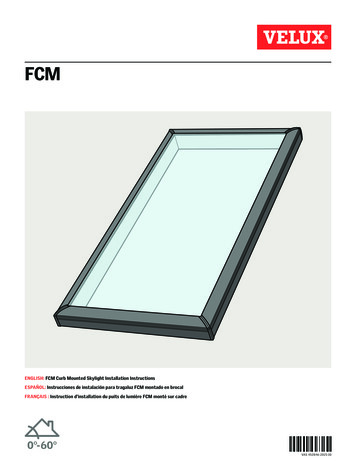
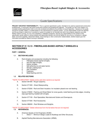
Illuminator Tube SkylightInstallation InstructionsWhat You Need To KnowReview this Information Prior toBeginning InstallationThese instructions have been designedto help install your Illuminator TubeSkylight easily and safely. We’ve included aparts list, list of tools required, installationinstructions for various types of roofingmaterials and ceiling designs, handy tips,and safety precautions. Please read theseinstructions thoroughly before installingyour Illuminator Tube Skylight. Pay particular attention to the assemblydiagrams, assembly order, and partnames. Identify and organize all parts beforeassembly. Make a list of the tools and componentsyou will need for each installationlocation.Following these instructions carefullywill greatly enhance your ability to installyour tube skylight and enjoy flawlessperformance for many years.Caution: The tube skylight is notdesigned to hold your weight or theweight of tools or other objects.Walking/placing objects on the skylightcould cause personal injury and propertydamage. A damaged skylight shouldbe repaired immediately. For safeinstallation and use, do not deviate fromthese installation instructions.WarningSafety information: Wear safety glasses and work gloveswhen using power tools. Use protective work gloves while handlingtube sections to protect hands from sharpedges.Pre Installation ChecklistTube Installation/Location Before installation, carefully survey theattic area of your desired location. Makesure your tube can avoid any wiring,plumbing, roof valleys, ceiling mountedregisters/fans, etc. Make sure that the location you pickon your roof for your dome/flashing isexposed to direct sunlight throughoutthe day. You will not want any trees,chimneys, etc. to cast a shadow onthe tube skylight’s dome. For best results always attempt to installthe tube as straight as possible, locatingthe dome/flashing directly above theceiling diffuser. Pre-size the required length of tubingneeded prior to starting the job. Your tube skylight kit comes withenough tubing for a 48" installation—if you require more tubing, you canpurchase additional extension tubesthrough your distributor. For cathedral ceiling, see page 7.Working on a roof is potentially dangerousbut you can significantly reduce the risk byfollowing these precautions: For long tube shaft installation, see page 8. Never work in wet, windy or coldconditions. Roofing materials can beslippery when wet; asphalt shingles arebrittle when cold and may crumbleunderfoot. Plan your installation for acalm, dry day. For tile roof installations, see page 10. Wear shoes with slip-resistant soles. Consult your local building official aboutlocal construction ordinances beforestarting your installation.What You Need to Know For metal roof installations, see page 9. For 14" skylight with 16" on-centerrafter spacing see page 4.Building Codes Consult your community covenants.Some subdivisions may not allow tubeson the street side of home.Determining roof pitch “Roof Pitch” is how far the roof dropsvertically for every 12" of horizontal run. Illuminator Tube Skylights are for roofslopes of 3:12 to 12:12.Important: Be sure to first read throughand then follow completely all step-bystep instructions. This will help to ensureproper installation and functionality. Expectinstallation to take from 1 to 3 hours.CALL US FIRSTDo not return to the store! For assistancewith your Illuminator Tube Skylightinstallation, or for additional productinformation, call our toll-free customerservice number: 1-800-GET-PINK WARNINGPOTENTIAL FIRE HAZARD.After removing the film lining from theinterior of tube shaft, a reflective innersurface is exposed. DO NOT leavetube shaft components unattended orexposed to direct sunlight prior to fullinstallation. Exposed surfaces may catchfire or incur heat damage as a result offocused sunlight until the tube shaft isfully installed with diffuser in place.1
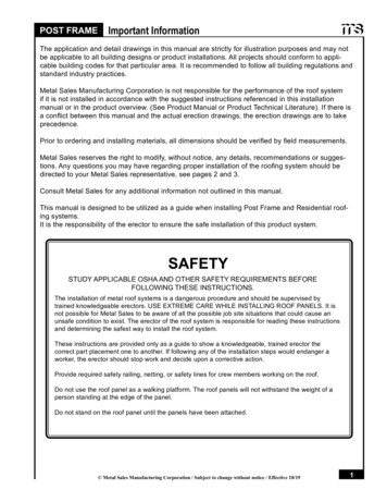
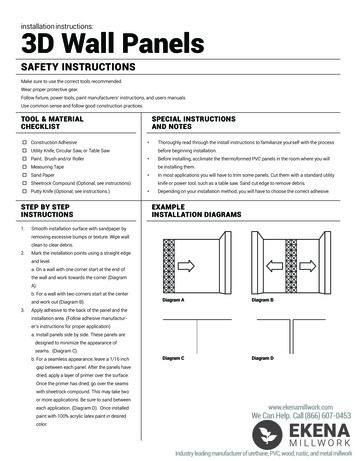
Tools Required & Parts IdentificationToolsCarpenter PencilPartsSolar Lens Dome(10" Dome shown)Claw HammerCoat Hanger WireOptional Spun AluminumRoof Flashing (Non Formable)Flat Pry BarLadderMetal ShearsRoof Flashing(Composite flashingshown)Phillips ScrewdriverPlumb LineOptional Formable AluminumRoof FlashingPower DrillPower SawSafety EquipmentAdjustable TubesMeasuring TapeNon-Curing/Non-Hardening RoofSealantClear Plastic Flashing(for Formable Flashing units only)Exterior SiliconeOther Roofing Applications(4) dome washersFormable Aluminum Flashing(All pitchedroof types—including Metal, Tile, and Shingled Applications)Secondary Clear Plastic Flashing(Required for use w/Formable Flashing)(4) ¾" dome screwsSeamless Aluminum FlashingImpact Resistant Tube Skylight w/Seamless Aluminum Flashing(approved for use outside and within highvelocity hail zones, such as Dade County, Texasgulf coast (pending))(9) 2" flashing screwsNote: Read through the section specificto your roof for additional parts andtools.(9) flashing washersCeiling Ring withFlip TabsLow-ProfileInsulated DiffuserLens Assembly2(1) roll of foil tape(2) hole cutting templatesTools Required & Parts Identification
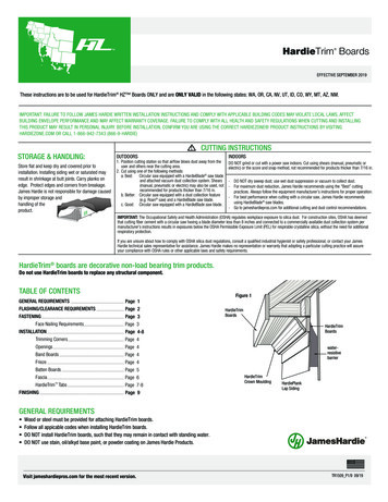
Section 1—PositioningDetermine the Desired Position ofthe Tube Skylight in the CeilingThese instructions outline the step-bystep process to install an Illuminator Tube Skylight. Before starting, review allinstructions and become familiar with theparts shown on the page 2.Section 2—Locating theRoof PositionSection 3—ComponentPreparationFor Straight Tube Installations1c.1a.Special Notes Always use safe procedures.In the attic, use a plumb line tofind a straight location from theceiling hole to the roof location.Center the opening for the tubebetween the framing members.Drive a nail up into the roof deckand through the shingles.Remove protective film frominside all tubes. Wear safety glasses when workingwith tools. Check all measurements beforecutting or drilling.WARNING It is helpful to have a second personassist during installation.Refer to Pre-installationChecklist for tube locationtips on page 1.1.Using a stud finder or hammer, finda location between the ceiling joists.Push a screwdriver or nail throughthe desired position.2.POTENTIAL FIRE HAZARD.For Angled Tube Installations1b.In the attic, if there areobstructions at the roof location(valleys, wires, pipes, ducts,framing, etc.), adjust tubes up to acombined 45 angle to find a paththat avoids interference. Centerthe opening for the tube betweenthe framing members. Drive a nailup into the roof deck and throughthe shingles.After removing the film lining from theinterior of tube shaft, a reflective innersurface is exposed. DO NOT leavetube shaft components unattended orexposed to direct sunlight prior to fullinstallation. Exposed surfaces may catchfire or incur heat damage as a result offocused sunlight until the tube shaft isfully installed with diffuser in place.Caution: From the hardware pack,select either the 10" or 14" hole cuttingtemplate, matching the size of the tubeskylight purchased.Cut and insert a section of coathanger wire through the hole. Thiswill make it easier to identify thehole location in the attic.Coat Hanger10" and 14" TemplatesNote: Trial-fitting your tubing will helpin determining adjustability and need foradditional extensions.3.Tip: It is recommended that you put all ofyour tools and rooftop components in a boxor bag for easy transfer to the roof.In the attic, locate the coat hangerwire. Adjust its location, centeringthe opening for the tube betweenthe framing members. Important:Ensure framing members WILLNOT be cut or compromised.Check wire visibility in the ceilingbelow as well as from the hole thatwill be cut in the roof.Section 1—Positioning; Section 2—Locating the Roof Position; Section 3—Component Preparation3
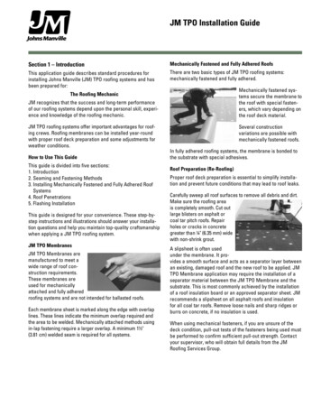
Section 4—On the Roof See page 8 for metal roof installation. See page 9 for tile roof installation.1.Select the correct hole cuttingtemplate for the tube (10" or 14").Be sure to use correct template.Important: For 14" skylight with 16" oncenter rafter spacing, the 14" templatewill draw a line that overlaps the rafters.Be sure to adjust your cutting angle toavoid cutting into the rafters.7.RafterSecure flashing to roof with 2"flashing screws and washers. Foraluminum flashing (Both spun andformable aluminum. See images onpage 2), use 9 screws and washersin an evenly spaced, circular patternaround the 10" or 14" hole. Thecircular pattern should be a 21"diameter for the 10" unit and a 24"diameter pattern on the 14" unit.Traced Line4Cut Line510" and 14" Templates2.Locate the protruding nail. Use thecorrect hole-cutting template totrace the diameter while using theouter template hole.Tip: The vertical seam of the reflective tubeshould point to the East or West to avoidirregular light patterns in your room.5.3.474.Use a reciprocating/sabre saw to cutthe roof hole.67Use a flat pry bar to carefully breakthe seals on the shingles upslopeabove the cut hole. Use a clawhammer to remove nails on theshingles above the cut hole.Generously apply roof sealantaround bottom of flashing. Slide topand sides of roof flashing under topshingles.Tip: We recommend using an asphalt roofingcement meeting ASTM D4586, Type 1.5Optional Spun Aluminum Roof Flashing(Non Formable)Note: Spun aluminum flashing does nothave pre-drilled holes.8.For injection molded flashing, use 8screws and washers in the preformedholes for the 10" and 14" unit.9.10.Important: Seal screw heads withroof sealant.Tip: Drill a hole inside the tracedcircle to insert saw blade.For angled tube installation, reachand adjust the adjustable tube soit points to the wire in the ceiling,or adjust the angle of the tube andthen insert tube into flashing.Important: For short shaft cathedral styleinstallation see page 7. Do notinstall dome yet.6.Slide top adjustable tube (pink label)into the flashing to check for properalignment.Note: Adjust tubes by lightly turning, usingone hand on each end.4Section 4—On the Roof
Section 4—On The Roof Cont’dSection 5—Inside the Room Cont’dSection 6—In the Attic11.Important: For 14" skylightwith 16" on-center rafterspacing, the 14" template willdraw a line that overlaps therafters. Be sure to adjust your cuttingangle to avoid cutting into the rafters.Tip: The vertical seam of the reflective tubeshould point to the East or West to avoidirregular light patterns in your room.Using the ¾" dome screws anddome washers (dome washers havethe rubber backing—rubber backingshould face the dome), mount thedome on the flashing aligning the“N” (molded into outer edge of thedome) towards the North.RafterImportant: At this point, if youpurchased a solar dimmer, this is whereyou reference the dimmer instructions,packaged with the dimmer unit.1.Gently set the bottom adjustabletube flange down on the trim ring.Do not snap in place at this time.Traced LineTrim RingCut LineFlip Tab2.Flip Tab2.Use a keyhole/drywall saw to cutthe hole.Tip: Dome screws should be snug but donot over tighten creating pressure againstthe dome.Tip: You may have to drill a hole inside thetraced diameter circle to insert saw blade.12.3.Cover dome screw heads andwashers with an exterior silicone.Section 5—Inside theRoom1.Slide the trim ring up into yourceiling hole. Make sure the flip tabsare turned in. Reach through holeand turn flip tabs out to hold ringin place.4.Section 5—Inside the Room; Section 6—In the AtticIf you have an angled installationyou will need to twist your bottomadjustable tube (blue label) so itlines up with the top adjustable tubeabove. (Be sure you have removedthe protective film.)Note: Adjust tubes by lightly turning,using one hand on each end.3.Measure distance from the top ofroof flashing to ceiling to determineproper trimming of length of tubes.Distance fromtop of flashingto face of ceiling(take longestmeasurement)Using the correct hole cutting guide(10" or 14") for your size tube, anda pencil, locate protruding wire inthe ceiling and trace the diameterusing the inner template hole of thetemplate marked “A”.Secure the ceiling trim ring bytightening the screws. See above.Lock Tab4.5.Slide bottom adjustable tube overthe outside of top adjustable tube.6.Tape ALL tube seams securely withfoil tape to keep dust, moisture, andinsects out of the tube.Now you can push down to lock thebottom adjustable tube securely intothe lock tabs of the ceiling trim ring.5
Section 7—Cutting YourTubeImportant: Once contactis made with adhesive stripon an extension tube, partscannot be repositioned.1.Before removing adhesive strip andassembling the extension tube, besure to measure and cut if necessary.Wear gloves when working withsharp edges.Section 9—Cathedral Ceiling/Short Shaft InstallationStart with regular installation instructionsbeginning on page 1.5.On the roof, mark the protrudingtube at the top of the flashing collarwith a felt pen. This will indicatewhere the extra length of tubingmust be trimmed off for a shortshaft install.6.At the ceiling, slide the temporaryshim out of your way and pull tubesection back out of the ceiling.7.Wearing protective gloves, carefullytrim away the excess aluminum tubingusing your felt pen marks as a guide.Note: The solar powered dimmer willnot work with a cathedral ceiling orsome short installations due to spacerestrictions.1.Tip: When trimming extension tubes, alwaysmeasure and start from the wide end wheretube end diameter 10" or 14".Place bottom adjustable tube(blue label) (with the flanged enddown) through the rough-cut holein the ceiling.62.If necessary, use metal shears toshorten the extension tube. Allow fora 1" overlap at each end where youwill connect each tube to another.3.Once extension tubes are sizedto the proper length, remove tanbacking paper from adhesive strip onedge of extension tube. Beginning atone end of the extension tube,over-lap the edges of the tube(s),aligning the edge of the tube alongthe crimp on the other side.AdhesiveStripOnce contact is made with adhesive strip,parts cannot be repositioned.672.Guide the top portion of the tubeup through the roof flashing soit protrudes upward through theflashing collar on the roof.3.Place a temporary shim orruler across the ceiling opening.(Approximately 1 8" thick)4.Center the tube over the ceiling cutout, resting the tube down onto theshim. (The shim will keep the tubefrom falling through the ceiling.)8.Remove the protective film from theinside of the tubing.9.Place the tube section back intothe ceiling making sure to align andcenter it inside the roof flashingcollar. Place shim back across thecut-out.Section 8—Inside the Room1.Install the diffuser assembly by aligningthe diffuser with the three tabs onthe trim ring. Turn clockwise untilsnug in place on the ceiling.25Ceiling Trim Ring34Lens Diffuser & InsulatorTip: Diffuser should be rotated at leastthrough two “clicks”. (Full rotation is four“clicks”) to attach to trim ring.Installation Complete!6Section 7—Cutting Your Tube; Section 8—Inside the Room; Section 9—Cathedral Ceiling/Short Shaft Installation
Section 9—Cathedral CeilingInstallation Cont'd10.2.Open the box containing the diffuserassembly and separate the ceilingring from the diffuser. Install only theceiling ring into the cut-out.3.11.Install the solar lens dome ontothe flashing collar. See dome installinstructions page 5, then return tothis page for further instructions.Rotate the insulated ceiling diffuseronto the ceiling trim ring.You can now remove the shim fromthe ceiling and allow the tube to restcentered over the ceiling ring.Installation Complete!Section 11—Long ShaftInstallationFor long shaft installation, use steps listedbelow, referring to those listed on previouspages for more specific install details.1.On roof, locate and install topadjustable tube (pink label) into roofflashing. Install ceiling ring at ceiling.Install bottom adjustable tube (bluelabel) in attic as seen in diagrambelow.2.Frame 2 x 4 support between joists.Span from roof to ceiling with alength of 2 x 4 flat to outside of eachadjustable tube creating a “spine”.3.Put a (2) 2½" pan-head, sheetmetal screw (not included) in eachconnecting extension.4.Slide next tube section in and attachwith screw(s). Continue until all butone extension is connected. Cut andinstall last section of extension tube.5.Seal ALL joints with foil tape.Go to page 5 “Inside the Room”to continue standard install.Section 10—CathedralCeiling on the RoofLong Shaft InstallationUse gloves!The trimmed edge of the tubewill be sharp!1.1TopAdjustableTubeCarefully press downward on thetrimmed end of the tube. It will lockdown into the three plastic lockingtabs located in the ceiling trim ring,securing the tube into the rubbergasket in the ceiling trim ring.3(2) 2½" SheetMetal Screws22x4SupportOptional Long ShaftInstallation, showingadjustable tubes atan mAdjustableTube1Section 9—Cathedral Ceiling/Short Shaft Installation ; Section 10—Cathedral Ceiling on the Roof; Section 11—Long Shaft Installation7
Section 12—Metal Roof Installation Using Formable Aluminum FlashingCut Hole in RoofStart with regular installation instructionsbeginning on page 1.1.After finding your roof location, drillup through the roof until it pushescarefully through the panel, on theroof side. (An assistant on the roof isrecommended during this step.)2.Select the correct hole cuttingtemplate for the tube (10" or 14").3.6.Cut a slit through the METAL ROOFPANEL ONLY across the horizontalline. Use gloves for safety.11.“Dry-fit form” the lower side ofthe flashing to conform to thepanel ridges.7.With your safety gloves on, besure your cut is smooth and free ofsharp edges.12.8.Slide the clear plastic flashingthrough the slit under the uppermetal panel and underlayment, thendown under the lower metal panel.Be sure the opening is aligned withthe cut hole.Once flashing is formed over thepanel ridges to your satisfaction,apply a generous bead of sealantto the underside of the lowerflashing section.13.14.Press formed flashing downaround roofing material.Locate the drilled hole. Use thecorrect hole cutting template totrace the diameter using the outertemplate hole. A nail inserted intothe hole will help guide the template.9.4.Run a continuous bead of sealantbetween the clear plastic flashingand the next layer of roofing aroundthe opening.Use a reciprocating/sabre saw to cutthe roof hole. Use a blade specificallymade for metal cutting. Use glovesfor safety.Attach with (9) 2" screws and ¾"diameter washers in an evenlyspaced circular pattern aroundthe 10" or 14" hole. The circularpattern should be 21" diameter onthe 10" unit and 24" diameter onthe 14" unit. Add additional 2" panhead screws as needed to secureedge of flashing.Position and Secure Flashing10.Tip: Drill a hole inside the traced circle toinsert saw blade.Slide the upper portion of theformable flashing under the metalpanel through the slit. Be sure toalign the flashing directly overthe hole.Important: Be sure to dab sealant onall screw heads to ensure a leak-freeinstallation.Cut Slit In Roof Panel5.8Draw a horizontal line across thecenter of the hole in the roof,running side to side the entire widthof the formable flashing.Refer back to page 4 “On theRoof” for complete installationinstructions.Section 12—Metal Roof Installation Using Formable Aluminum Flashing
Section 13—Tile Roof Installation Using Formable Aluminum FlashingFind Hole Location on RoofStart with regular installation instructionsbeginning on page 1.1.2.3.6.Select the correct hole cuttingtemplate for the tube (10" or 14").After finding your roof location, drillup through the roof. Then drive a4"-6" rod or spike up through theroof sheathing until it pushes thetile/shingles upward on the roofside. (An assistant on the roof isrecommended during this step.)Carefully remove the lifted tile andremove the rod/spike from it’s hole.Position the Clear Plastic Flashing9.Cut a slit through the underlaymentat the “3:00 and 9:00” positions. Besure the slit is as wide as the clearplastic flashing.Slit cut inunderlayment7.Position the formable aluminumflashing piece perfectly centeredover the punctured hole.Use the correct hole cuttingtemplate to trace the diameterof the outer template hole. A nailinserted into the hole will help guidethe template.Slide plasticflashing upthrough slit10.4.Trace the opening of the formablecollar base so that your tiles aremarked. This will assist in trimmingthe roofing materials to properly fitthe flashing once in place.8.Use a reciprocating/sabre saw to cutthe roof hole. Use gloves for safety.Tip: Drill a hole inside the traced circle toinsert saw blade.Remove Tiles and Cut Hole5.Carefully remove the tiles or shinglesfrom the “work area.” Set themaside in the same order or patternas when attached to the roof.Be sure openingis aligned withthe cut holeSlide the clear plastic flashingup through the slit under theunderlayment. Be sure theopening is aligned with the cuthole. Remove any fasteners/nailsthat obstruct the clear plasticflashing.Dry-Fit All The Parts11.Do a practice run of installingthe clear plastic flashing,formable aluminum flashing, andthe refl ective tube. Rememberto use protective gloves whenhandling metal.Position the components in place.If the hole cut in the roof deck istoo small to allow proper positionof components, enlarge the holewith power saw.FormableAluminumFlashingTopAdjustableTubeClear PlasticFlashingSection 13—Tile Roof Installation Using Formable Aluminum Flashing9
Section 13—Tile Roof Installation Using Formable Aluminum Flashing Cont’dReinstall TilesSeal the Clear Plastic Flashing12.Secure the clear plastic flashingto the roof deck by applying agenerous, continuous bead ofsealant on the underside of theflashing.Tip: you might find it difficult contouringthe formable aluminum flashing to fit thedownhill tiles. Try shifting those tiles furtherdownhill to allow more aluminum to workwith. Or add a 2" shim to the roof deck sothe formable aluminum flashing is angled tothe roof rather than parallel to it.19.Secure The FormableAluminum Flashing17.Position and Shape the FormableAluminum Flashing13.Reinstall the trimmed tiles at thesides of the roof cutout, makingsure to install them in the samepattern as they were removed,from bottom to top. These tilesneed to be installed on top of theformable aluminum flashing.Make any required adjustments intrimming the tiles or shingles for aproper fit around the side of theformable flashing collar. A “properfit” is one that is within 1"-2" of thealuminum vertical wall.Once the formable aluminumflashing is shaped to match thedownhill tiles, clean and dry thesurfaces of aluminum, underlayment,and tile. Apply roofing sealant to alladjoining surfaces.Attach these tiles with nails,caulk the heads of the nails withexterior silicone.Position the formable aluminumflashing in place by centering itsopening with the hole cut into theroof deck.Top AdjustableTubeFormableAluminumFlashing18.Clear PlasticFlashing14.Centering is best achieved byinserting the reflective tube intothe opening of the aluminumflashing letting the fit of the tubeto-roof hole serve as a guide.15.The uphill half of the formablealuminum flashing should be layingon top of the underlayment, whilethe downhill half of the flashingshould be laying on top of thedownhill tiles.16.Secure the formable aluminumflashing with the metal flashingscrews and washers. The 9 screwsprovided should be installed in acircular, equally spaced patternaround the aluminum collar toimprove water sealing. Dab roofsealant on each screw to create awater-tight seal. The 10" unit hasa 21" diameter screw pattern; the14" unit has a 24" diameter screwpattern.Screws in Circular Pattern20.Reinstall the final tiles alongthe uphill edge of the formableflashing. This requires the rowof tiles to be lifted slightly andmay be necessary to loosen theirattachments. Secure the tiles withnails, caulk the heads of the nailswith sealant.21.Quick setting mortar may be usedto fill in the gaps between the tileand aluminum collar to provideproper run-off of water. Check allareas for proper sealing and waterrun-off.Manually shape the downhill edgeof the formable aluminum flashingto match the surface of the tiles.Tip: Paint the formable aluminum flashingto match the color of the tiles or shingles, ifdesired.Screws Anchored into Optional Shim22.Install remaining components ofthe tubular skylight as instructedin standard installation starting onpage 4 “On the Roof”.Tip: The optional wooden shim can be usedas a screw anchor as well.10Section 13—Tile Roof Installation Using Formable Aluminum Flashing
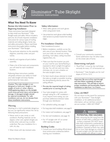
Energy Star /NFRC Label For new homes and projects requiringbuilding permits, cut out NFRC labelonce product installation is complete. Affix to diffuser ring as shown andsecure with tape. Cut along dotted line and place underdiffuser ring after installation. U-Factor: the lower the value the lowerthe rate of heat flow. Less heat flows soheating and cooling bills are reduced. Solar Heat Gain Coefficient (SHGC):Measure ability to block heat caused bysunlight. The lower the SHGC the moreit reduces air conditioning costs. Label is to remain in place until finalinspection to qualify project forEnergy Star. Energy Star /NFRC Label11
OWENS CORNING ROOFING AND ASPHALT, LLCONE OWENS CORNING PARKWAYTOLEDO, OHIO, USA 436591-800-GET-PINK www.roofing.owenscorning.comPub. No. 10017417-B. Printed in U.S.A. June 2012. THE PINK PANTHER & 1964–2012 Metro-Goldwyn-Mayer Studios Inc. All Rights Reserved. Thecolor PINK is a registered trademark of Owens Corning. 2012 Owens Corning.All Rights Reserved.ENERGY STAR and the ENERGY STAR mark are registered trademarks of theU.S. EnvironmentalProtection Agency.1216593-880
Illuminator Tube SkylightInstrucciones de instalaciónLo que necesita saberLea esta información antes decomenzar con la instalación.Estas instrucciones se diseñaron paraayudarlo a instalar la claraboya tubularIlluminator de manera fácil y segura. Seincluye una lista de piezas, una lista de lasherramientas necesarias, las instruccionesde instalación para varios tipos de materialesy diseños de techos, consejos prácticos ymedidas de seguridad. Lea atentamenteestas instrucciones antes de instalar laclaraboya tubular Illuminator . Preste especial atención a los diagramasde ensamblaje, el orden de ensamblajey los nombres de las piezas. Identifique y organice todas las piezasantes de comenzar a ensamblar. Haga una lista de las herramientas y loscomponentes que necesitará para cadaubicación de la instalación.Seguir estas instrucciones cuidadosamenteincrementará enormemente su habilidadpara instalar la claraboya tubular y disfrutarde un desempeño perfecto durante años.Precaución: La claraboya tubular no estádiseñada para soportar su peso o el peso delas herramientas u otros objetos. Caminaro colocar objetos sobre la claraboya puedecausar lesiones y daños a la propiedad.Una claraboya dañada debe repararsede inmediato. Para una instalación y unuso seguros, siga estas instrucciones deinstalación detenidamente.AdvertenciaTrabajar en un techo es potencialmentepeligroso pero puede reducirsignificativamente el riesgo siguiendoestas precauciones: Nunca trabaje en climas fríos, ventososo con lluvia. Los materiales del techopueden ser resbaladizos cuandoestán mojados; las tejas de asfalto sonquebradizas cuando hace frío y puedenromperse bajo los pies. Planifique lainstalación para un día seco y calmo. Use calzado con suelas antideslizantes.Lo que debe saberInformación de seguridad: Use gafas de seguridad y guantes de trabajocuando utilice herramientas eléctricas. Use guantes de trabajo protectores cuandomanipule las secciones de tubo paraproteger las manos de los bordes filosos.Lista de verificación de preinstalaciónInstalación/ubicación del tubo Antes de la instalación, inspeccionecuidadosamente el área del ático de laubicación deseada. Asegúrese de queel tubo pueda evitar cualquier cableadoeléctrico, cañerías, limahoyas, registrode chimeneas o ventiladores montadosen el techo, etc. Asegúrese de que la ubicación que elijaen el techo para la cúpula/tapajuntas estéexpuesta a la luz directa del sol durantetodo el día. No querrá que árboles,chimeneas, etc. proyecten una sombraen la cúpula de la claraboya tubular. Para obtener mejores resultados, siempreintente instalar el tubo lo más derechoposible, ubicando la cúpula/tapajuntasdirectamente sobre el difusor del techo. Mida la longitud requerida de tuberíaantes de comenzar el trabajo. El kit de la claraboya tubular viene contubería suficiente para una instalaciónde 48 pulg. Si requiere más tubería,puede comprar tubos de extensiónadicionales a través de su distribuidor. Para cielorrasos de gran altura, consultela página 7. Para la instalación de ejes del tubo largos,consulte la página 8. Para la instalación en techos metálicos,consulte la página 9. Para la instalación en techos con tejas,consulte la página 10. Para claraboyas de 14 pulg. con espaciosobre el centro de la viga de 16 pulg.,consulte la página 4.Códigos de edificación Consulte al funcionario de edificaciónlocal sobre las ordenanzas locales deconstrucción antes de comenzar con lainstalación. Consulte las cláusulas de la comunidad.Algunas subdivisiones pueden no permitirtubos sobre el lado de la calle de la casa.Determinación de la inclinacióndel techo La “inclinación del techo” es la medidaen que el techo cae verticalmente porcada 12 pulg. de recorrido horizontal. Las claraboyas tubulares Illuminator son para techos con una inclinación deof 3:12 hasta 12:12.Importante: Asegúrese de leer primeroel documento completo y recién despuésseguir las instrucciones paso a paso. Estoayudará a garantizar una instalación yfuncionalidad adecuadas. La instalación llevade 1 a 3 horas.LLÁMENOS PRIMERO¡No devuelva el producto a la tienda!Llame a nuestro número gratuito deatención al cliente si necesita asistenciapara la instalación de la claraboya tubularIlluminator : 1-800-GET-PI
step instructions. This will help to ensure proper installation and functionality. Expect installation to take from 1 to 3 hours. CALL US FIRST Do not return to the store! For assistance with your Illuminator Tube Skylight installation, or for additional product information, call our toll-free customer service number: 1-800-GET-PINK WARNING