Transcription
Terrain-Relative Navigation for Autonomous Underwater VehiclesD.E. Di MassaW.K. Stewart stewart@whoi.eduWoods Hole Oceanographic InstitutionBlake - MS7Woods Hole, MA 02543-Abstract For map-matching navigation of autonomous underwater vehicles, the central problem is localizing a sonar (orvideo) image of the seafloor in an existing global bathymetricmap. The terrain-relative navigation methodology presentedhere is grounded in the Kalman Filter framework and uses itsthree basic steps: prediction, measurement, and update. In theprediction step, the vehicle location with uncertainty (state andstate covariance) is estimated by using the previous vehiclelocation and dead reckoning. In the measurement step, the current sonar image is matched to the map using the mean absolute difference dissimilarity parameter. Because of the potentialfor large uncertainties in both the depth values of the image andthose of the map, a suite of good matches is accepted ratherthan the single best match. The localion of each match is considered a measurement of the vehicle position. Finally, eachmatch (measurement) is weighted probabilistically using dataassociation techniques, and the resulting best estimate and associated uncertainties comprise the navigation update. Thisupdated position is then used as a ba,sisfor the next predictionstep, and the process is repeated. Using real bathymetric datafrom a section of seafloor near the Mid-Atlantic Ridge betweenthe Kane and Atlantis Transforms, B simulation showing thesuccess of this algorithm will be presented.I INTRODUCTIONAlthough terrain variations have been exploited for landbased vehicles and aircraft, and bathymetric navigation hasbeen discussed for surface vessels for over 25 years [ 5 ] , littlehas actually been achieved in exploiting sub-surface terrainvariations for the purpose of navigation. This has primarilybeen attributed to the lack of accurate maps. If there isenough local variation in the seafloor, navigation relative tothe bathymetric contours or to identified features should bepossible. Qualitatively, the greater the bathymetric variability and the finer the map resolution, the more distinct anypiece of bathymetry will be, and, consequently, the moreaccurate navigation is likely to be.Recently, bathymetric sonars have improved significantlyand will continue to do so, and there has been an increase inthe development and improvemen1 of bathymetric maps.Much research is being done in the area of bathymetric mapmaking [3, 12, 131, but the work presented here assumes thatone of the available map-making procedures has already provided a digital bathymetric map with known accuracy andresolution.The major contribution of this work is the development ofa terrain-relative navigation system for autonomous under-0-7803-4108-2/97/ 10.00 0 1 997 IEEEwater vehicles (AUVs) that considers multiple location measurements at a single time step and explicitly represents thelocalization uncertainty at all times. The system incorporatesdata-association techniques that are usually used for targettracking and adapts them to this application. Image-processing algorithms are used to obtain the map-matched positionmeasurements and to enable the necessary calculations to becompleted without prohibitive computational demands. Thenavigation system is scale-independentand will operate successfully using maps with a wide range of resolutions. Also,the system uses the uncertainty on the map in the localization algorithms, so that highly uncertain maps or maps withvarying degrees of uncertainty can be used. Ref. [6] providesa more detailed presentation.I1 BACKGROUNDRef. [9] is one of the first to investigate the feasibility ofbathymetric navigation for AUVs. In this work, Kullanderassumes that the AUV has an on-board inertial navigationsystem and uses terrain navigation to periodically update theposition similar to a cruise missile. He concludes from simulation that applying this technique to underwater environments is much more difficult than on land because it is moredifficult to collect the necessary data and, furthermore, thatdata may have large errors. The success of the operation mayalso be dependent on knowledge of the properties of thewater, which affect the performance of the sensor.Ref. [2] takes the terrain contour matching concepts onestep further and provides the first thorough evaluation of terrain-relative navigation for AUVs. Bergem investigates thefeasibility of using data from a multibeam sonar and matching the profiles to a pre-stored map continuously. Heassumes he has a sufficiently detailed map, so the entireregion can support bathymetric navigation. His system isbuilt around a Kalman Filter and was implemented andtested with real data from the Oslo fjord of Norway. He successfully demonstrates that navigation with bounded errorscan be achieved solely based on information from bottomtopography.Bergem selects only the best match for simplicity, but hedoes state that data-association methods, which would incorporate multiple matches, have many of the required characteristics needed for a navigation system. Although thesetechniques are grounded in the Kalman Filter framework,they are non-linear and more complex’ than a standard Kal-541Authorized licensed use limited to: UNIVERSIDADE DO PORTO. Downloaded on December 4, 2008 at 06:56 from IEEE Xplore. Restrictions apply.
man Filter. Additionally, they were “originally designed fortarget tracking, and the parameters that are needed are difficult to estimate for other applications, e.g., the target detection probability and the spatial density of false alarms [2].”I also agree that it is wise to use multiple pieces of information gained by matching the profile to the map, rather thanby choosing only the best match. In many cases, the uncertainties involved can result in the best match not providingthe best navigational update. I do use the complex algorithmsand techniques of data association and do encounter the difficulties predicted by [2], but I have found realistic solutionsfor this elative navigation is a map-matching methodology that assumes the vehicle has both a digital bathymetricmap stored on-board and the ability to image the seafloor.The crux of the navigation problem is to localize the sonarimage in an existing map. The entire map need not besearched, only a small local area. However, because of theuncertainties involved, e.g. uncertainty in the sonar image,uncertainty in the sonar processing, and uncertainty on thesupplied map, simply finding the best match between thesonar image and the map may not result in the best localization. It is also important to explicitly represent the uncertainty on the accepted vehicle location.To find a good match, first, a criterion for determining the“goodness” of a match (the agreement between the imageand the map) must be defined, and, second, this “goodness”must be evaluated throughout the search area. Ref. [ I l lstates that for digital signals, although there are manyoptions, the “two most commonly used choices are thesquared difference and the absolute difference.” The goodness criterion chosen here is the mean absolute difference(MAD) between the bathymetry values of the image and themap. The absolute difference, and not the difference squared,was chosen to avoid magnifying error values due to fliers. Byevaluating the MAD throughout the search area, the matchescan be ranked by their “goodness” and the top candidatesselected as a set of potential vehicle locations.To complete the localization problem the information inthese matches must be combined to determine a best estimate of the true location. Estimation theory is used toachieve this, and to keep terminology consistent with thatfield, each match in the list is designated a measurement ofand the true state is the true location of the image in the map.The Kalman Filter framework is used in this estimationproblem and data-association techniques build upon thisframework to achieve the actual updates (mathematical derivations for these techniques are found in [ 1,4,8]).employed in tracking algorithms to determine the best estimate of target location by appropriately associating eachmeasurement with possible targets and evaluating the validity or usefulness of each measurement [I, 71.The Probabilistic Data Association Filter (PDAF) is arecursive sub-optimal Bayesian algorithm for situations inwhich there is only one target of interest, but several measurements of the target state are available at each time step[I]. The PDAF is similar to the Kalman Filter in that itassumes that the past can be approximately summarized by astate that is normally distributed according to the latest estimate and covariance matrix and that the current state is predicted using the latest estimate and a model of the systemdynamics. However, the PDAF differs from the Kalman Filter because a validation region or gate is defined around thepredicted state and a weighted sum of the measurementsinside the gate is used to update the state. These measurements are weighted probabilistically as a function of theinnovation, the detection probability, the gate probability,and the false-alarm rate. Thus, the new state estimate isbased on the information contained in multiple measurements.The basic advantage of the PDAF is that all measurementsin the vicinity of the expected value (i.e. within the validation gate) are considered with some probability of being correct. The disadvantage is that the resulting estimate isguaranteed to be “wrong” in the sense that the single correctmeasurement was not selected to stand alone. However, inmy case, it is better to have an estimate with larger values ofcovariance than it is to choose the wrong measurement andhave the A W truly believe it is somewhere that it is not.B. Probabilistic Data Association with Amplitude Informa-tionFor my purposes, the main disadvantage of the PDAF isthat once a measurement is validated the match “goodness”of that measurement is no longer considered. To include thisin my algorithm, I turn to the PDAF augmented with amplirude infomuztion (PDAFAI) [IO], where I substitute thematch “goodness” for raw signal amplitude. In fact, if handled appropriately, the “amplitude” can correspond to anyfeature or features that one may wish to use in determiningmeasurement weights, such as level of backscatter or degreeof bathymetric variability. In the PDAFAI, each validatedmeasurement is weighted probabilistically as a function ofboth its distance from the prediction (innovation) and thematch quality.A. Probabilistic Data AssociationData association (or data correlation) is typically542IV SIMULATIONFor this demonstration the sonar image is a one-dimensional profile represented as a list of depth values, equallyspaced, with the same spacing as the pixels of the bathymet-
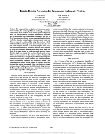
ric map. The state vector is26.35"N 46.05"W on the western flank of the Midriwhere x and y indicate the column and row, respectively, ofthe matrix, which represents the digital map. For simplicity,the state is measured directly, so the measurement vector isthe same as the state:z(k 1) E](2)The overall navigation process fidlows the Kalman Filterframework shown in Fig. 1. First, the state and state covariance are predicted by an internal niivigation system, such asdead reckoning or inertial navigation,2(k 1Ik) n(klk) u f k ) ,(3)where u(k) is a control input. From this information, thesearch area of the map is determined, then the matchingalgorithm is employed to produce ai list of measurements bymatching the profile to the map. Finally, the state estimateand state covariance are updated using the data-associationtechniques,P ( k I l k 1) P ( k l l k ) ' W ( k l)v(k l ) , (4)where W(k l) is the Kalman Gain and v(k l) is the combined innovation calculated using the PDAFAI. Ref. [6] provides a more thorough explanation of this procedure.This technique is demonstrated using an example fromreal deep-ocean bathymetry approximately located at7PredictionAtlantic Ridge (see Fig. 2). The map was created from datataken by a 120-kHz sidescan sonar. The region shown is a2495 m x 2620 m section of a steep ridge bounded on oneside with a sedimentary plateau and on the other by an areaof gradual slope. The pixel spacing is 5 m in both directions,and the minimum and maximum depths are 3769 m and463 1 m, respectively.The terrain-relative navigation methodology is both sensorand scale independent. It can operate with any point spacingand any uncertainty and need not be modified for each application. For this reason, the terrain-relative navigation algorithms are constructed in terms of the pixel spacing insteadof specific dimensions.Presented in this paper is a single trackline which has initial conditions of both the true and estimated states aswith a state covariance matrixr 1501.to 5iThe control input vector isr-lu sonar profilek4,--TIFig 1. Kalman Filter Framework.1. Predict state, state covariance, and measurement, Calculate innovationcovariance and Kalman Gain, 2. Determine search parameters as a function of innovation covariance, 3. Employ coarse-to-fine matching algorithm with beam search to get list of good matches, 4. Validatemeasurements inside the gate, 5. Update statr: estimate and state covariance using data association 1,"1 n,(7)LLJwhere n is a Gaussian white noise vector with covariance 0.6( m / for) the x and y velocities. So, the vehicle travels parallel to the y axis, perpendicular to the profile orientation. Thetrue trackline continues for 150 time steps and ends atISearch Parameters 2-x pi.(8)The vehicle starts in a relatively flat area with large measurement uncertainty. It then passes through steep terrain, whichprovides very accurate navigation. Towards the end of thetrackline, the terrain has less variability and again gives largemeasurement uncertainty, but this time more so in the xdirection.Figs. 3 and 4 show the true and navigated tracks and theassociated covariances. At the beginning of the trackline, theestimated state does not track the true state well and thecovariances stay large. As the vehicle moves into the steepterrain, more accurate navigation is achieved, and the estimated state holds the true track fairly well with small covariance values. Then, the vehicle leaves this area and enters aregion with less variable terrain, and the estimated positionagain does not track the true state well. In this difficult area,the state covariance grows as the estimate becomes well offtrack. Eventually, the measurements pull the estimate backtowards the correct values, so the navigation does not diverge543Authorized licensed use limited to: UNIVERSIDADE DO PORTO. Downloaded on December 4, 2008 at 06:56 from IEEE Xplore. Restrictions apply.
50t50100150200250300350400450x position (pixels)Fig 2. Contour Plot of Deep-Ocean Bathymetry with Trackline.greatly.Figs. 5 show the overall distance error between the trueand navigated tracks, along with the errors in x and y. Theaverage x, y, and overall errors are 5.67 m, 4.14. m, and 7.82m, respectively, for the full trackline, but the plots of Figs. 4and 5 clearly show three separate sections of navigation performance. These three sections correspond to the three typesof terrain this trackline covers. The first section contains timesteps 1 through 45. Average errors are 4.95 m and 7.65 m forthe x and y directions, and 9.70 m for the overall averageerror. The second section is for time steps 46 through 80 andaverage errors are 0.64 m, 0.70 m, and 1.05 m for x, y, andoverall error, respectively. The final section is for time steps81 through 150, and the average errors are 8.65 m and 3.61m for n and y, with an overall average error of 9.99 m.The covariance values, given in Fig. 4 in units of pixel2,should be multiplied by 25 to obtain true covariance valuesin m2. The average covariances for x, y, and x y are 39.93 m2,35.40 m2, and -0.02 m2, respectively. Segmenting the covariances as above, for Section 1, the average values for x, y, andx y are 67.00 m2, 78.50 m2, and 1.25 m2; for Section 2, 3.96m2, 3.15 m2, and 0.00 m2; and for Section 3,40.47 m2, 23.88m2, and -0.85 m2. However, the covariance information ismore useful when compared to the error at each time step.Fig. 6 shows the track error normalized over the covariances of Fig. 4. The overall distance error is compared to thestate covariance matrix at that time step to obtain the value ofT, which indicates the size of the uncertainty ellipsoid thatcorresponds to the overall distance error vector. For example,when T l, an ellipsoid is drawn at l o , and the endpoint ofthe difference vector lies on the surface of this ellipsoid.When T 2, an ellipsoid is drawn at 2 0 , and the endpoint ofthe difference vector lies on the surface of this ellipsoid. So,the value of Tis the number of sigmas needed to define theellipsoid whose surface contains the endpoint of the difference vector. At each time step, the actual deviation values aredifferent, but for this figure the information is normalized sodifferent time steps can be compared direAt the start of the track,but so is the covariance, an544
III100150100150100150i& 20LLJf 100050time step0':102902922942962%300302x position (piels)3043063080031050time stepFig 3. True (-) and Navigated (*) Tracks.0;20LUCB 10Un"050limestepFig 5. x, y, and Overall Errors.again, but the covariance has not yet grown sufficiently, sothe normalized value is large (up to 9), indicating poor performance. This value does reduce as the covariance grows tobetter represent the accuracy expected.V SUMMARYcovariance (pkels2)Fig 4.Covariances for Track, xx(-), yy( ), xy(o).fairly good, i.e., Tis small. In the second section, the errorsare smaller, but so are the covariance ,values, and the performance is still good. However, when the vehicle moves intothe third section of the terrain, the error values become largeIn this paper, I demonstrate the success of a new terrainrelative navigation algorithm for autonomous underwatervehicles. The approach depends on a supplied digital bathymetric map and the ability of the vehicle to image the seafloor. These images are matched to the map in the localneighborhood and ranked according to the mean absolutedifference. The algorithm functions independent of the pixelsize of the supplied map, so even maps with coarse resolution can be used successfully.Validated measurements are weighted probabilistically as afunction of both the match quality and the innovation using aprobabilistic data association filter with amplitude information (PDAFAI). This means that all good matches are consid-545Authorized licensed use limited to: UNIVERSIDADE DO PORTO. Downloaded on December 4, 2008 at 06:56 from IEEE Xplore. Restrictions apply.
141JBrown, Robert G. and Patrick Y.C. Hwang,Introduction to Random Signals and Applied KalmanFiltering, 2nd ed., John Wiley and Sons, Inc., New York,1983.[5] Cohen, P.M., Bathymetric Navigation and Charting, USNaval Institute, Annapolis, MD, 1970.[6]Di Massa, Diane, Terrain-Relative Navigation forAutonomous Underwater Vehicles, Ph.D ThesisMassachusetts Institute of TechnologylWoods HoleOceanographic Institution Joint Program, 1997.[7] Fortmann, T.E., Y. Bar-Shalom, and M. Scheffe, “SonarTracking of Multiple Targets Using Joint ProbabilisticData Association”, IEEE Journal of OceanicEngineering, vol. OE-8, pp. 173-84, July 1983.[8]“010050Gelb, Arthur, ed., Applied Optimal Estimation, TheMIT Press, Cambridge, MA, 1974.[9] Kullander, L., “Development of a Terrain NavigationSystem for AUVs,” in Proc. Intl. Symp. on UnmannedUntethered Submersible Technology, pp. 494-501,Durham, NH,June 1989.150time stepFig 6. Track Error Normalized over Covariance (2).ered with some probability of being the correct match.As expected, results show more accurate navigation inareas with greater bathymetric variability and less accuratenavigation in flatter areas with more gentle terrain contours.Terrains with minimal bathymetric variability, such as theabyssal plains, may not yield profiles with sufficient uniqueness to support accurate navigation with this approach. Formost places, the uncertainties assigned to the navigationpositions reflect the ability of the system to follow the truetrack. A more thorough analysis with additional simulationscan be found in Ref. [6].[101 Lerro, Donald and Yaakov Bar-Shalom, “AutomatedTracking with Target Amplitude Information,” Proc. ofthe I990 American Control Conference, pp. 2875-80,San Diego, CA, May 23-25,1990.[ l l ] Lim, Jae S., Two-Dimensional Signal and ImageProcessing, Prentice Hall, Englewood Cliffs, NJ, 1990.[12] Singh, H., D. Yoerger, R. Bachmayer, A. Bradley, andW.K. Stewart, “Sonar Mapping with the AutonomousBenthic Explorer (ABE),” in Proc. Intl. Symp. onUnmanned Untethered Submersible Technology, pp.367-75, Durham, NH, Sept. 1995.[ 131 Stewart, W.K., Multisensor Modelling Underwater withACKNOWLEDGEMENTSThe authors would like to thank Henrik Schmidt for hisinput to this research. This work was sponsored by the Officeof Naval Research, Contract number N00014-96-1-5028.This is WHO1 Contribution 9493.Uncertain Information, Ph.D. Thesis, MassachusettsInstitute of TechnologyNoods Hole OceanographicInstitution Joint Program, 1988.REFERENCES[l]Bar-Shalom, Yaakov and Thomas E. Fortmann,Tracking and Data Association. Academic Press Inc.,Boston, MA, 1988.[21Bergem, Oddbjorn, Bathymetric Navigation ofAutonomous Underwater Vehicles Using a MultibeamSonar and a Kalman Filter with Relative MeasurementCovariance Matrices, Sc. D. Thesis, Department ofInformatics and Computer Science, University ofTrondheim, Norway, 1993.[3]Blackington, J.G., D.M. Hussong, and J.G. Kosalas,“First Results from a Combination Sidescan Sonar and aSeafloor Mapping System (SeaMARC U),” in Proc. ofthe 15th Annual Offshore Technology Conference, vol.1, pp. 307-14, Houston, TX, May, 1983.546Authorized licensed use limited to: UNIVERSIDADE DO PORTO. Downloaded on December 4, 2008 at 06:56 from IEEE Xplore. Restrictions apply.
Terrain-Relative Navigation for Autonomous Underwater Vehicles D.E. Di Massa W.K. Stewart Jr. 508-289-3230 508-289-2644 ddiimassa@ alum.mit.edu kstewart@ whoi.edu