Transcription
WhitepaperIntroduction to remote controlsystems and remote maintenancesystems for system monitoringAuthor:Eike WedekindIndustry PR5 PHOENIX CONTACT 2015
Table of contentsOverview: development of remote control technology 3Difference between remote control and remote maintenance 3Communication protocols 5Basic requirements 6Protocols 8Transmission paths 12Continuous connections in the mobile communication network 15Selection matrix 16PHOENIX CONTACT2
Overview: development of remote control technologyJust a few years ago it was extremely difficult to monitor and maintain distributed stations. Thereason for this was that the remote systems were either unable to communicate with a controlcenter or communication involved a great deal of effort and expense.Today, all installations in supply and disposal technology, such as water, gas or energy supply,pipelines or even transportation technology applications, must be connected to a central controlsystem. This allows smaller installations such as pumping stations, transformer stations ortransformer substations to be monitored and controlled remotely. This connection presents newchallenges for the technology.Remote control and remote maintenance have since become the established standard incommunication. Remote systems or external stations can be easily connected to the controlcenter using a wide range of transmission paths. Standardized transmission is made easier thanksto defined, standardized protocols. The predictive maintenance that has been made possible as aresult of this enables huge cost savings.But which communication path is best suited to the relevant application?This white paper is intended to provide all users with a practical selection guide to thecommunication mechanisms and media for remote maintenance and remote control technologythat are relevant to them.Difference between remote control and remote maintenanceIn industrial communication, there is a vast difference between remote control and remotemaintenance, even when using identical technology. This often leads to confusion when it comesto selecting the right communication media. The particular features of the different applicationsare therefore described below.Remote maintenanceDue to globalization, central control systems are being used to operate systems and machinesthat are in ever more distant locations. In addition, the installed systems are constantly growingin complexity. This often leads to problems when needing to diagnose and remove errors in theevent of a fault. Nowadays in the event of a fault, there is much more to it than just remotemaintenance. Thanks to developments in recent years, complete support and monitoring of theproduction process is now possible.Remote maintenance describes remote access to a station for fault diagnostics or formaintenance purposes. This saves costs, as a technician does not have to be on site or travellong distances in order to return the system to operation. Downtimes are also reduced.PHOENIX CONTACT3
Remote control technologyUsing suitable remote control technology it is possible to influence all the parameters of thesubstations at all times. System states are continuously displayed in the control center. Therequired documentation of flow rates or liquid levels, for example, can be stored centrally formany years. Thanks to special protocols, process data can be transmitted securely over wide areanetworks, even with low bandwidth and with poor transmission quality.Communication used to be performed via proprietary control lines with discrete digital andanalog signals. As processes became more complex, more information was needed from theprocess, and it was possible to process this information in control systems, the discrete lineswere, in many cases, replaced by serial connections via permanent line modems. Stations that didnot have proprietary permanent line connections were connected via analog dial-up connections,leased permanent lines or wireless systems. Mobile communication connections were also laterused. One of the disadvantages of dial-up connections is that there is no permanent connectionto the control system and, as with voice telephony, connection establishment takes some time.Recently there has been a clear move away from serial transmission paths toward IP-basedcommunication. Modern communication options such as Internet, DSL, GPRS/EDGE/3G, UMTSor LTE are also integrated in remote control technology.Remote control technology describes the remote monitoring and control of physicallyseparate system parts by means of data transmission. Measured values and controlcommands are transmitted over long distances and visualized, processed, and stored in acontrol center. In contrast to remote maintenance, remote control requires a permanentconnection to a remote station in the vast majority of cases.Figure 1Control roomPHOENIX CONTACT4
Communication protocolsThere are specific protocols for every type of industrial communication. Fieldbuses with definedtransmission paths are one particular protocol type. Even the cables are often specified andprocess information is usually exchanged cyclically with the fieldbus stations.Another group of industrial protocols originates from the time of serial communication viapermanent lines. These are mostly what are referred to as polling protocols. One example is theModbus protocol, which is used worldwide.A typical feature of this form of data exchange is that the control system polls each externalstation cyclically. Polling either only identifies changes or transmits all data points to the controlsystem. However, in the event of a connection abort, it is impossible to later determine whathappened at the external station during this time or whether specific threshold values wereexceeded. The advantage of these protocols is their easy parameterization. The disadvantage isthe setup of time dependencies which can be laborious.With the introduction of remote control technology and the associated expansion of systems, anew type of industrial protocol was needed. Previously a physical connection was requiredbetween the control system and the external station, which limited the amount of data thatcould be sent. Over time the mobile communication network was increasingly used to connectexternal stations to the control system. As a result it was no longer possible to use time-criticalpolling protocols.Mobile communication networks are storage networks that can retain the individual data packetswhich are then only reassembled again at the receiver. Once a connection has been established,the user no longer has to deal with data transmission. It is controlled by using TCP/IP, forexample.Connection abort is a known disadvantage of mobile communication networks. While aninterruption on a permanent line means there is a fault, when it comes to data links via a mobilecommunication network, connection aborts are frequently caused by the provider withoutwarning.This behavior places new demands on a transmission protocol. It must provide internal securitymechanisms in order to prevent data loss in the network.PHOENIX CONTACT5
Basic requirementsA remote control protocol must feature the following in order to satisfy current requirements:Bidirectional, event-oriented transmissionIt must be possible to send data to the external station and receive data from the externalstation simultaneously. For example, an external station must not be hindered by control systempolling if it is transmitting an alarm message.Storage of process information,e.g., in the event of connection interruptionsSome of the data in the processes is relevant for billing. It must not be lost as a result of aconnection abort and must be stored by the external station as historical data until it has beenreceived by the control system.Time stamping of process informationFor the control system to be able to reconstruct the data trend, the historical data must at leasthave an exact time stamp.Time synchronizationIn order to reconstruct data trends using the time stamp, all external stations of a system mustuse the same time as the control system. A remote control protocol must therefore offer theoption of synchronizing all devices in the system.Serial communication via proprietary permanent lineIn some systems, distributed system parts are connected via the supplier's proprietary permanentlines. One example is the connection of the pumping station to the central process control system.Serial communication is possible here because copper cables are traditionally installed along withthe supply lines. With protocols according to IEC 60870-5-101 or IEEE 1815 (DNP3), forexample, the system is equipped with communication standards that are established in remotecontrol technology. All requirements for secure remote control technology are thereforesatisfied. In the event that the permanent line fails, the selected remote control protocol ensuresthat the data for a pumping station is stored in the remote control device.PHOENIX CONTACT6
Communication via TCP/IP orcablesIf no proprietary cables are present,communication via a TCP protocol fornetworking distributed systems to thecontrol system is a reliable method fordata transmission. Protocols according toIEC 60870-5-104 or IEEE 1815 (DNP3)support standardized connections forstormwater overflow tanks, pumping stationsor well shafts – via the mobile communicationnetwork or wired communication dependingon the application. If such interfaces alreadyexist at the control system, the remote controldevices used can reliably communicate with thecontrol system. Depending on the protocolused, communication is event-orientedand prepared for the use of GPRS-basedhardware. In the event of the failure of thecommunication infrastructure, the remotecontrol protocol ensures that data is stored.Figure 2Mobile phone towerPHOENIX CONTACT7
ProtocolsProtocols for remote controlVarious remote control protocols are listed and described below:IEC 60870-5-101IEC 60870-5-101 is an official communication standard for remote control technology ininfrastructure sectors. This protocol is used as a general transmission protocol between(network) control systems and substations. Messages are transmitted via serial connections. Thisstandard enables devices and systems for remote control and station control technology fromdifferent manufacturers to communicate with one another without the need for fundamentaladaptations.Protocol IEC 60870-5-101 is the standard protocol for serial data transmission in Europe and isalso used in Asia.IEC 60870-5-104IEC 60870-5-104 enables communication between the control center and substation via astandard TCP/IP network. The TCP protocol is specifically used for connection-oriented, securedata transmission. As the name of the standard suggests (“Network access for IEC 60870-5-101using standard transport profiles”), the protocol follows standard IEC 60870-5-101 with respectto the application layer. The biggest advantage of IEC 60870-5-104 is communication via a TCP/IPnetwork, which enables simultaneous data transmission with multiple devices and services.Because the Internet can be used for communication, security by means of data encryption is animportant topic. In addition, this is an event-oriented protocol where the substation can senddata to the control system automatically.Protocol IEC 60870-5-104 is the standard protocol for data transmission with TCP/IP in Europeand the USA and is also used in some Asian countries.IEEE 1815 – DNP3DNP3 (Distributed Network Protocol) enables communication between a substation and controlroom via a serial connection as well as via an Ethernet connection.DNP3 was developed between 1992 and 1994 by Westronic and is based on IEC 60870-5.However, the protocol is more restrictive and offers less room for interpretation than itsEuropean counterparts.Over time DNP3 has been extended to include authentication. Authentication means thatexternal stations check the authenticity of the control system before executing criticaloperations. They do this by exchanging encrypted data.Protocol IEEE 1815 is the standard protocol for serial and data transmission via TCP/IP. It is usedin North, Central, and South America, South Africa, the UK, Australia, and also in Asia.PHOENIX CONTACT8
ODP – Open Data PortThe Open Data Port (ODP) communication protocol was developed by Bremen-based companyVidec and is used for GPRS-based communication between a control system and remote controlsubstations. The AX ODP server installed in the remote control center makes all data from theremote control substations available via a standardized OPC interface. This concept offers theuser open communication with various OPC-based process control systems.Both serial and Ethernet-based ODP communication has been implemented in the ReSyOdpfunction block library. The various hardware requirements must be observed when configuringthe remote control substations.The ODP specification is divided into three areas and supports online data, historical data, andalarms and messages.Online dataThe process image data is read cyclically from the PLC and displayed in the control system via theOPC interface. Switching operations can also be performed from the control center.Historical dataHistorical data is retrieved cyclically or in a user-controlled way. The time-stamped historicaldata is sorted in chronological order into *.csv files by the AX ODP server. The memory capacityin the PLC depends on the number of variables and the corresponding memory cycle.Malfunctions, alarms, and messagesMalfunctions, alarms, and messages are transmitted to the control system by the substation in anevent-oriented way. These can then be stored in chronological order and evaluated in the controlsystem.If the external stations are connected via the ODP server by means of GPRS, they cancommunicate with virtually any control system. In order to do this, the AX ODP server must beinstalled in the control center. The ODP server developed specifically for GPRS communicationmakes data for connection to the control system available via OPC. They are thereforemanufacturer-neutral and can communicate with every OPC-based control system.PHOENIX CONTACT9
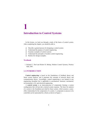
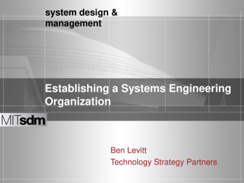
Protocols (not for remote control)In addition to the remote control protocols listed, a number of other protocols have becomeestablished. These protocols are frequently used, however they do not save any data in the eventof a connection interruption. Data that does not reach the control system can no longer bereproduced.ModbusModbus is frequently used to allow devices from different manufacturers to communicate withone another based on a standard protocol. The Modbus protocol is a communication protocolbased on a master/slave or client/server architecture. It was developed in 1979 by Modicon forcommunication with programmable logic controllers. Modbus has become a de-facto standard inthe industry, as it is an open protocol. Modbus can be used to connect a client (e.g., a PC) andseveral servers (e.g., measurement and control systems). There are three versions of Modbus:Modbus ASCII, Modbus RTU, and Modbus TCP. The last two are by far the most popular.Modbus is probably the most widely used communication protocol in the world.SEAB-1FThe SEAB-1F protocol was developed in 1972 by AEG and was later given the name Modnet-1F. Itconnects substations and control centers from the Geadat-120 product range. SEAB stands forserial system bus and 1F stands for remote control technology.What is specific to the SEAB-1F protocol is that all data traffic is time-critical. The control centerrequests data from a substation which must be received within a specified time.The difficulty when using SEAB-1F is that in order to operate several devices on one cable, FSKmodems must be used. This requires very precise parameterization of the communication times(Tv, Tn, Tp). If just one of these times is off, errors will occur during data exchange, or the entiresystem will be so badly disrupted that communication will no longer be possible.There are still many systems in use today where the control system uses the SEAB-1F protocolfor communication with the substations. This technology has proved itself over 4SEAB-1FFigure 3Connection of an SEAB-1F substation to IEC 60870-5-104PHOENIX CONTACT10
SMSSMS stands for Short Message Service and is also used for communication between an externalstation and the control system – usually as an alarm message. The SMS can be used by anyreceiver: mobile phone, landline, fax or e-mail account. In addition, several programmable logiccontrollers can be networked together. The provision of an acknowledgment function ensuresthat the SMS reaches the receiver. Otherwise, the SMS is sent to another address.Use of the SMS function in remote control technologyIn addition to its function as a means of communication, the SMS service is also used to controland monitor technical devices and equipment. In applications where only alarm messages are tobe transmitted or where control commands are sent relatively infrequently, the SMS service ofthe GSM network is a viable option for reasons of cost.For example, industrial modems offer configurable warning and alarm inputs and are thereforeideal for monitoring small applications. An alarm SMS can be sent directly to a service technician'smobile phone, informing them directly of the type of error and its location. When dealing with anincreased number of messages or control commands, GSM modems can also be connected toprogrammable logic controllers. This allows the I/O area of the PLC to be linked to textmessages. It is also frequently the case that an SMS alarm message is not only intended to be sentto a mobile phone, but also to the alarm management of a control system. When a PLC iscombined with a GSM modem, SMS messages can, for example, be received, decoded, andforwarded to a control system in a variety of ways.PHOENIX CONTACT11
Transmission pathsWired transmissionWhen a proprietary data line is used for theremote control technology connection, e.g., inthe power supply network of municipal works,it should be noted that if the copper cable islonger than 1.5 kilometers, the signals to betransmitted must be modulated in order toincrease the range. Whether based on coppercables or fiber optics, this means that processinformation can be exchanged with a centralcontrol system over long distances.Figure 4Server roomPermanent line modemSerial interfaces (RS-232, RS-485) are often available at the remote control substations and in thecontrol system; these interfaces should be used to transmit standard protocols such as IEC60870-5-101. Analog permanent line modems, which are specifically tailored to industrialrequirements, are used to transmit this serial data. A digital signal is modulated to a carrierfrequency in the high-frequency range by the transmitting modem; the original information is thenretrieved by the receiving modem by means of demodulation. This technology has a maximumtransmission speed of 33.6 kbps.SHDSL modemIt is not usually possible to remotely program external stations that are connected in series. AnEthernet-capable network is required for this. An SHDSL modem can be used to make a serialcommunication network Ethernet-capable. Modems based on the newer DSL standard operatewith higher carrier frequencies and larger bandwidths for the phone line than the models basedon the older standard (narrowband). With industrial SHDSL permanent line modems, existingcables can also be used for modern Ethernet applications. Transmission speeds of up to 30 Mbpsare possible via in-house cables. Automatic detection of the DSL data rate, as well as automaticadjustment to the Ethernet cable (1:1, crossed) and protocol transparency simplify startupconsiderably. In addition to point-to-point connection, a line structure (daisy chain) is alsopossible. With respect to transmission, there are modems for Ethernet, fieldbus or serialinterfaces.Fiber opticsNowadays when new trunk lines are laid they are usually fiber optic (FO) lines. FOcommunication is immune to electromagnetic interference and, depending on the technology,allows several kilometers to be covered with a bandwidth in excess of 100 Mbps. Mediaconverters can be used to forward Ethernet data as well as all common remote control orfieldbus data. Even in power distribution, external stations, e.g., in a substation, are usuallyconnected to the central node point via fiber optics.PHOENIX CONTACT12
Non-wired connections (wireless)If no cable is present, other means of communication must be found. Depending on the distanceand the required bandwidth, it is also possible to use wireless connections. Depending on therequirements, one of the following three connections can be used:Trusted WirelessThe application of Trusted Wireless was developed specifically for industrial use. As a result,large distances of up to 3 kilometers can be covered from one serial interface to another. Forexample, Trusted Wireless is used for communication between the control center and a pumpingstation. There should be a line of sight between the systems.With visual contact, it is possible to transmit over a distance of up to 5.5 kilometers, e.g., whennetworking well fields. In the event of failure, a new communication path is selected and datatransfer is still ensured. 255 devices can be connected per network. Multiple networks can beoperated in parallel without any restrictions.Figure 5Wireless in practiceBluetoothBluetooth is a standard for wireless transmission over short paths involving up to seven devices.The 2.4 GHz ISM frequency band is used, which does not require a license and is free of chargeworldwide. It allows serial data to be transmitted even if another network is already active.PHOENIX CONTACT13
Bluetooth in useSlip rings are frequently used to transmit measured values or process data from the scraperbridge of a wastewater treatment plant to the PLC. This technology is very high maintenance,resulting in high costs for the operator. Additional signals are often required, however there areno slip rings available for them. By using Bluetooth devices, maintenance costs can be saved andany number of signals can be transmitted over a distance of up to 400 meters with visual contact.WLANWLAN is recommended in applications where, in addition to process-specific data, data fromwebcams or IP phones is also transmitted. Wireless Local Area Network describes a localwireless network with a data rate of up to 54 Mbps in the wireless application which can be usedby a large number of devices. Wireless is particularly suitable for mobile monitoring, operation,and data acquisition as it can be easily integrated into IT networks.PHOENIX CONTACT14
Continuous connections in the mobile communicationnetworkThe mobile communication network or the Internet provide a solution for transmission over longdistances and on a global scale. An almost constant connection can be achieved in this way.GSM – 1GGlobal System for Mobile Communications (GSM) is a standard for mobile communicationnetworks that is primarily used for telephony and SMS transmission.Text messages containing up to 160 characters can be sent in this way, e.g., for alarm generationor the transmission of status information. In the event of a power grid fault, a PLC sends an errormessage to the relevant user who can promptly rectify the error. Before this technology wasused, the technician had to localize the fault on site before being able to remove it.GPRS/EDGE – 2GGPRS (General Packet Radio Service) supports transmission of up to 210,000 bps. This is possiblebecause the data packets are split into many small packets that are reassembled again at thereceiver. Since billing by providers is based on the volume of data and not the connectionduration, a permanent modem connection is not a problem. Security plays an extremelyimportant role here. The use of preconfigured modems with a fixed IP interface with point-topoint connections enables the constant connection of devices. In order to ensure secure datatransmission, for a fee it is possible to apply for a closed network from the provider. A secondoption may be to use hardware solutions (security routers and GPRS routers) which protect datacommunication by means of VPN encryption, for example.UMTS – 3G3G UMTS (Universal Mobile Telecommunications System) is a third generation mobilecommunication standard with transmission speeds of up to 7.2 Mbps in the GSM network.LTE – 4GDue to the ever-increasing use of smartphones and tablets, as well as the networking of standalone machines and devices with the control center, increasing strain is being placed on thenetwork. So that this high level of demand can also be accommodated in future, a new technologylike LTE is required. LTE (Long Term Evolution) is also referred to as the fourth generation (4G)of mobile communication technology. The technology is the new standard in mobilecommunication and is the successor to UMTS (Universal Mobile Telecommunications System,3G). This technology enables a high-speed connection of up to 300 Mbps and, unlike conventionalstandards, it supports different bandwidths. A peak data rate of up to 300 Mbps for downloadand 75 Mbps for uplink with 5-millisecond latency is theoretically possible. An important featureof LTE is its downward compatibility with older technologies. LTE retains the basic schema ofUMTS, which means that the existing infrastructure can still be used. Missing components cansimply be retrofitted.DSLDSL (Digital Subscriber Line) refers to a series of transmission standards for bit transmission. Inthe high data range, this standard can achieve a transmission speed of up to 500 Mbps usingsimple copper cables.PHOENIX CONTACT15
Selection matrixMobile communication network systemsVarious communication options are available for data transmission in remote or wide-rangingnetworks and for monitoring machines all over the world. This overview helps users to select theoptimum form of communication for the application.GPRS /EDGE TransmissionspeedIdeal field ofapplicationWorldwideIEC 60870-5-104DNP3ODPModbus TCPMobilecommunicationnetworkcoverageBasic monthlycharge andbilling based onthe transmitteddata volumeUp to 7.2 Mbps Remote orkcoverageBasic monthlycharge andbilling per SMSmessage– Connection ofEthernet networks Connection ofsubstations Worldwide alarmgenerationWorldwideIEC 60870-5-101 MobileDNP3communicationModbus RTUnetworkcoverageBasic monthlychargeand usagedependentbilling based ontimeSerial data up to9600 bps Transmission ofI/O information Worldwide remoteprogrammingconnectionWorldwideIEC 60870-5-101 AnalogDNP3telephoneModbus RTUconnectionBasic monthlychargeand usagedependentbilling based ontimeSerial data up to33,600 bps Worldwide remoteprogrammingconnectionWorldwideIEC 60870-5-104DNP3ODPModbus TCPAnalogtelephoneconnection andDSL accessBasic monthlycharge(usage/timeindependentbilling)Annex A:Up to 25 Mbpsdownstream(from the Internet)Up to 3.5 Mbpsupstream(to the Internet)Annex B:Up to 24 Mbpsdownstream(from the Internet)Up to 1 Mbpsupstream(to the Internet) Remote dataacquisition Connection ofsubstations Connection ofEthernet networksUp to20 kmIEC 60870-5-104DNP3ODPModbus TCPExisting two/four-wire cablefor optimumrange InstallationEthernet data of upandto 30 Mbpsmaintenancecosts for two/four-wirecable No monthlycosts Remote dataacquisition Connection ofsubstations Connection ofremote PROFIBUSdevices Connection ofEthernet networks Connection ofsubstationsSMSGSMWired systemsPublic telephone ionSHDSLPHOENIX CONTACT16
nsmissionspeedIdeal field ofapplicationUp to 4km–Line of sight foroptimum rangeFree of chargeand no licenserequired in the2.4 GHz ISMband Serial data up to115,200 bps I/O databidirectional andunidirectionalWireless networkingof sensors andactuatorsUp to 2kmIEC 60870-5-104 Line of sight foroptimum rangeDNP3ODPModbus TCPFree of charge WLAN data ratesand no licenseof up to 300 Mbpsrequired in the Ethernet net data2.4 GHz andrates of up to5 GHz ISM band95 MbpsUp to300 mIEC 60870-5-104 Line of sight forDNP3optimum rangeODPModbus TCPFree of chargeand no licenserequired in the2.4 GHz ISMbandWireless systemsTrustedWireless2.0WLANBluetoothSerial data upto 187,500 bpsEthernetUp to 1 Mbps net ProtocoltransparentEthernetcommunicationwith PLCs, I/Ostations, PCs, etc. Wireless networkintegrationof remoteinstallations Wirelessprogrammingconnection Cable replacementfor PROFIBUS,PROFINET,Modbus RTU/TCP,and serial TCP/IPdata in the case ofbusy and mobilesystem partsPHOENIX CONTACT17
PHOENIX CONTACTPhoenix Contact is a worldwide market leader for components, systems, and solutions inthe fields of electrical engineering, electronics, and automation.Our extensive manufacturing capability means that it is not just screws and plastic and metal parts that are produced in-house, but also highly automated assembly machines.The product range consists of components and system solutions for energy supply includingwind and solar energy, device manufacturing and machine building, as well as control cabinetmanufacturing.With a wide range of terminal blocks and special terminal blocks, PCB terminal blocks andconnectors, cable connection technology, and installation accessories, we offer innovativecomponents. Electronic interfaces and power supplies, automation systems based on Ethernet and wireless, safety solutions for people, machines, and data, surge protection systems,as well as software programs and tools provide compre
Serial communication via proprietary permanent line In some systems, distributed system parts are connected via the supplier's proprietary permanent lines. One example is the connection of the pumping station to the central process control system. Serial communication is possible here because copper cables are traditionally installed along with