Transcription
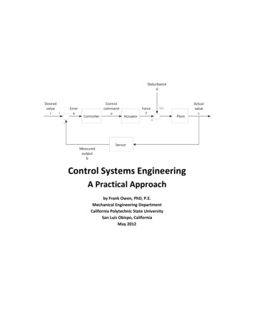
1Introduction to Control SystemsIn this lecture, we lead you through a study of the basics of control system.After completing the chapter, you should be able to Describe a general process for designing a control system.Understand the purpose of control engineeringExamine examples of control systemsUnderstand the principles of modern control engineering.Realize few design examples.Textbook1. Richard C. Dorf and Robert H. Bishop, Modern Control Systems, PrenticeHall, 2001.1.1 INTRODUCTIONControl engineering is based on the foundations of feedback theory andlinear system analysis, and it generates the concepts of network theory andcommunication theory. Accordingly, control engineering is not limited to anyengineering discipline but is applicable to aeronautical, chemical, mechanical,environmental, civil, and electrical engineering.A control system is an interconnection of components forming a systemconfiguration that will provide a desired system response. The basis for analysisof a system is the foundation provided by linear system, which assumes a causeeffect relationship for the components of a system. A component or process to becontrolled can be represented by a block as shown in Figure 1.1
Basic Electronics2ProcessInputOutputFigure 1 Process under controlAn open-loop control system utilizes a controller or control actuator to obtainthe desired response as shown in Figure 2. The open-loop control system utilizesan actuating device to control the process directly without using device. Anexample of an open-loop control system is an electric Figure 2 Open-loop control system (no feedback)A closed-loop control system (Figure 3) utilizes an additional measure of theactual output to compare the actual output with the desired output response. Themeasure of the output is called the feedback signal. A feedback control system isa control system that tends to maintain a relationship of one system variable toanother by comparing functions of these variables and using the difference as ameans of control. As the system is becoming more complex, the interrelationshipof many controlled variables may be considered in the control scheme. Anexample of closed-loop control system is a person steering an automobile bylooking at the auto’s location on the road and making the appropriateadjustments.
Basic Electronics3Difference or Actuating utputResponseMeasurement DeviceFigure 3 Closed-loop feedback system.1.2 TEMPERATURE CONTROL SYSTEMSFigure 4 shows a diagram of temperature control of an electric furnace. Thetemperature in the electric furnace is measured by a thermometer, which is ananalog device. The analog temperature is converted to a digital temperature by anA/D converter. The digital temperature is fed to a controller through an interface.This digital temperature is compared with the programmed input temperature,and if there is any error, the controller sends out a signal to the heater, through aninterface, amplifier, and relay, to bring the furnace temperature to a desired value.ThermometerA/DConverterRelayFigure 4 Temperature control system.AmplifierInterfaceInterfaceINPUT
Basic Electronics41.3 CONTROL SYSTEM DESIGNThe following table shows the control system design process.1. Establish control goals2. Identify the variables to control3. Write the specifications for thevariables4. Establish the system configurationand identify the actuators5. Obtain a model of the process, theactuator, and the sensor6. Describe a controller and select keyparameters to be adjusted7. Optimize the parameters andanalyze the performance Variables to control are the quantities or conditions that are measuredand controlled.Process is a natural, progressively continuing operation marked by aseries of gradual changes that succeed one another in a relativelyfixed way and lead toward certain result or end.A system is a combination of components that act together andperform a certain objective.
Basic Electronics51.4 DESIGN EXAMPLE: TURNABLE SPEED CONTROLBatteryTurntableDC MotorDC tor(DC Motor)Process(Turntable)ActualSpeedFigure 5 Open-loop control of speed of a turntable and a block diagram model.BatteryTurntableDC MotorDC AmplifierTachometerFigure 6 Closed-loop control of the speed of a turntable.
Basic Electronics61.5 DESIGN EXAMPLE: DISK DRIVE READ ntrolDeviceActuator andRead ArmSensorFigure 7 Closed-loop control system for disk drive.A hard disk uses round, flat disks called platters, coated on both sides with aspecial media material designed to store information in the form of magneticpatterns. The platters are mounted by cutting a hole in the center and stackingthem onto a spindle. The platters rotate at high speed, driven by a special spindlemotor connected to the spindle. Special electromagnetic read/write devices calledheads are mounted onto sliders and used to either record information onto thedisk or read information from it. The sliders are mounted onto arms, all of whichare mechanically connected into a single assembly and positioned over thesurface of the disk by a device called an actuator. A logic board controls theactivity of the other components and communicates with the rest of the computer.For details see Figure 8 and Figure 9.
Basic ElectronicsFigure 8 A hard disk.7
Basic ElectronicsFigure 9 Components of a hard disk8
Basic Electronics91.6 FEEDBACK CONTROL OF AN ANTIAIRCRAFT GUNGun Azimuth (Elevation)Demanded Azimuth (Elevation)ControlSystemGunDynamicsFigure 10 Feedback control of an antiaircraft system.
Basic Electronics10ExercisesE1.1A precise optical signal source can control the output power level to within 1%.A laser is controlled by an input current to yield the output power. Amicroprocessor controls the input current to the laser. The microprocessorcompares the desired power level with a measured signal proportional to the laserpower output obtained from a sensor. Draw the block diagram representing theclosed-loop control system.ErrorDesiredPower surement)Laser(Process)Output power
Basic Electronics11E1.6Automated highways may be prevalent in the next decade. Consider twoautomated highway lanes merging into a single lane, and describe a controlsystem that ensures that the vehicle merge with a prescribed gap between sured gapBrakesSteeringSensor(Radar)ActivevehicleActual gap
Basic Electronics12ProblemsP1.1Many luxury automobiles have thermostatically controlled air-conditioningsystems for the comfort of the passengers. Sketch a block diagram of an airconditioning system where the driver sets the desired interior temperature on adashboard abinCabintemperature
Basic Electronics13P1.10The role of air traffic control systems is increasing as airplane traffic increases atbusy airports. Engineers are developing air traffic control systems and collisionavoidance systems using the Global Positioning System (GPS) navigationsatellites. GPS allows each aircraft to know its position in the airspace landingcorridor very precisely. Sketch a block diagram depicting how an air trafficcontroller might utilize GPS for aircraft collision avoidance.Autopilot(controller)Desired flightPath fromtrafficcontrollerMeasured flight pathAllerons,elevators,rubber, andEnginepowerGlobal Positioning SystemAircraft(Process)Flight path
Basic Electronics14P1.21The potential of employing two or more helicopters for transporting payloads thatare too heavy for a single helicopter is a well-addressed issue in the civil andmilitary rotorcraft design arenas. A case of a multilift arrangement wherein twohelicopters jointly transport payloads has been named twin lift as shown in thefollowing figure. Develop the block diagram describing the pilots’ action, theposition of each helicopter, and the position of the load.12LoadMeasured separationdistanceDesired rSeparationdistanceAltitudeDesired altitudeAltimeterMeasured altitude(Measurement)
Basic Electronics15Design ProblemsDP1.2Many cars are fitted with cruise control that, at the press of a button,automatically maintains a set speed. In this way, the driver can cruise at a speedlimit or economic speed without continually checking the speedmeter. Design afeedback control in block diagram for a cruise control system.Controller1/kDesiredSpeedof autoset ginekDrive shaftspeedMeasuredShaft speedShaft speed meter
Introduction to Control Systems In this lecture, we lead you through a study of the basics of control system. After completing the chapter, you should be able to Describe a general process for designing a control system. Understand the purpose of control engineering Examine examples of control systems Understand the principles of modern control engineering. Realize few design examples .