Transcription
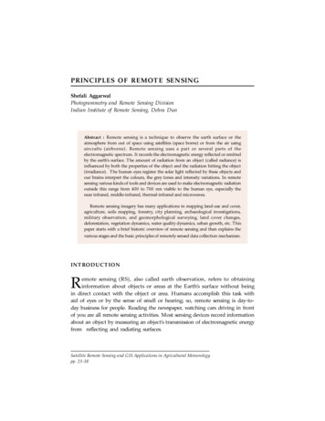
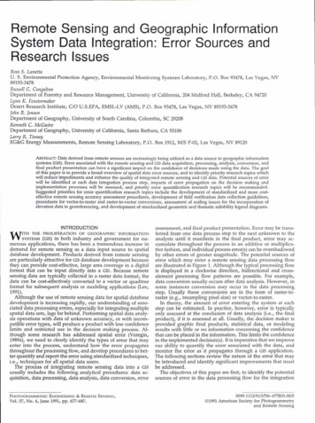
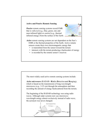
Active and Passive Remote SensingPassive remote sensing systems record EMRthat is reflected (e.g., blue, green, red, andnear-infrared light) or emitted (e.g., thermalinfrared energy) from the surface of the Earth.Active remote sensing systems are not dependent on the Sun’sEMR or the thermal properties of the Earth. Active remotesensors create their own electromagnetic energy that is transmitted from the sensor toward the terrain interacts with the terrain producing a backscatter of energy is recorded by the remote sensor’s receiver.The most widely used active remote sensing systems include:Active microwave (RADAR RAdio Detection and Ranging),which is based on the transmission of long-wavelengthmicrowave (e.g., 3-25 cm) through the atmosphere and thenrecording the amount of energy backscattered from the terrain.The beginning of the RADAR technology was using radiowaves. Although radar systems now use microwavewavelength energy almost exclusively instead of radio wave,the acronym was never changed.1
LIDAR (LIght Detection And Ranging),which is based on the transmission of relatively shortwavelength laser light (e.g., 0.90 µm) and then recordingthe amount of light backscattered from the terrain;SONAR (SOund NAvigation Ranging),which is based on the transmission of sound wavesthrough a water column and then recording the amount ofenergy backscattered from the bottom or from objectswithin the water column.RADARThe “ranging capability is achievedby measuring the time delay fromthe time a signal is transmitted tothe terrain until its echo is received.Because the sensor transmitted asignal of known wavelength, it ispossible to compare the receivedsignal with the transmitted signal.From such comparisons imagingradar detects changes in frequencythat form the basis of capabilitiesnot possible with other sensors.2
Sending and Receiving a Pulse of Microwave EMR System Components3
Brief History of RADAR 1922, Taylor and Young tested radio transmissioncross the Anacostia River near Washington D.C. 1935, Young and Taylor combined the antennatransmitter and receiver in the same instrument. Late 1936, Experimental RADAR were working in theU.S., Great Britain, Germany, and the Soviet Union. 1940, Plane-The circularly scanning Doppler radar(that we watch everyday during TV weather updates toidentify the geographic locations of storms) 1950s, Military began using side-looking airborneradar (SLAR or SLR) 1960s, synthetic aperture radar (SAR) 1970s and 1980s, NASA has launched two successfulSARs, SEASAT, Shuttle-Imaging Radar (SIR) 1990s, RADARSAT 4
Active Microwave (RADAR) Commonly Use FrequenciesBand DesignationsFrequency (ν)(common wavelengthsWavelength (λ)shown in parentheses)in cmin GHzK1.18 - 1.6726.5 to 18.00.75 - 1.1840.0 to 26.5Ka (0.86 cm)Ku1.67 - 2.418.0 to 12.5X (3.0 and 3.2 cm)2.4 - 3.812.5 - 8.0C (7.5, 6.0 cm)3.8 - 7.58.0 - 4.0S (8.0, 9.6, 12.6 cm)7.5 - 15.04.0 - 2.015.0 - 30.02.0 - 1.0L (23.5, 24.0, 25.0 cm)P (68.0 cm)30.0 - 1001.0 - 0.35
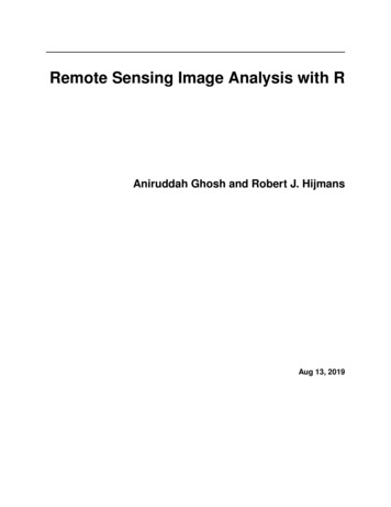
Airborne Side-Looking Radar (SLAR or SLR)Radar Nomenclature Nadirazimuth flight directionrange (near and far)depression angle (γ)look angles (φ)incidence angle (θ)altitude aboveabove-groundgroundlevel, H polarization6
Azimuth Direction The aircraft travels in a straightline that is called the azimuthflight direction.direction. Pulses of active microwaveelectromagnetic energyilluminate strips of the terrain atright angles (orthogonal) to theaircraft’aircraft’s direction of travel,which is called the range or lookdirection.direction. The terrain illuminated nearestthe aircraft in the line of sight iscalled the nearnear-range.range. Thefarthest point of terrainilluminated by the pulse ofenergy is called the farfar-range.range.Look DirectionThe range or look direction for anyradar image is the direction of theradar illumination that is at rightangles to the direction the aircraft orspacecraft is traveling.Generally, objects that trend (orstrike) in a direction that isperpendicular to the look directionare enhanced much more than thoseobjects in the terrain that lie parallelto the look direction. Consequently,linear features that appear dark in aradar image using one look directionmay appear bright in another radarimage with a different lookdirection.a.X - band, HH polarizationlook directionb.X - band, HH polarizationslook direction7
Depression AngleThe depression angle (γ) is the anglebetween a horizontal planeextending out from the aircraftfuselage and the electromagneticpulse of energy from the antenna toa specific point on the ground.The depression angle within a stripof illuminated terrain varies from thenearnear-range depression angle to thefarfar-range depression angle. Theaverage depression angle of a radarimage is computed by selecting apoint midway between the near andfarfar-range in the image strip.Summaries of radar systems oftenonly report the average depressionangle.Incident AngleThe incident angle (θ) is the anglebetween the radar pulse of EMR anda line perpendicular to the Earth’Earth’ssurface where it makes contact.When the terrain is flat, the incidentangle (θ) is the complement (θ(θ 90- γ) of the depression angle (γ). If theterrain is sloped, there is norelationship between depressionangle and incident angle. Theincident angle best describes therelationship between the radar beamand surface slope.Many mathematical radar studiesassume the terrain surface is flat(horizontal) therefore, the incidentangle is assumed to be thecomplement of the depression angle.8
RADAR ResolutionTo determine the spatial resolution at any point in a radarimage, it is necessary to compute the resolution in twodimensions: the range and azimuth resolutions.Radar is in effect a ranging device that measures the distance totoobjects in the terrain by means of sending out and receivingpulses of active microwave energy.The range resolution in the acrossacross-track direction isproportional to the length of the microwave pulse.The shorter the pulse length, the finer the range resolution.Azimuth resolution (Ra)Ra) is determined by computing the widthof the terrain strip that is illuminated by the radar beam.beam.9
Azimuth resolution (Ra)Ra) is determined by computing the widthof the terrain strip that is illuminated by the radar beam.beam. Thebeam width is inversely proportional to antenna length (L).Where S is the slant-range distance to the point of interest.This means that the longer the radar antenna, the narrower thebeam width and the higher the azimuth resolution.Synthetic Aperture Radar (SAR)A major advance in radar remote sensing has been theimprovement in azimuth resolution through the development ofsynthetic aperture radar (SAR) systems.Great improvement in azimuth resolution could be realized if alonger antenna were used.10
Synthetic Aperture Radar (SAR)Engineers have developed procedures to synthesize a very longantenna electronically. A SAR uses a relatively small antenna (e.g.,(e.g.,1 m) that sends out a relatively broad beam perpendicular to theaircraft. A greater number of additional beams are sent toward thetheobject. Doppler principles are then used to monitor the returns fromall these additional microwave pulses to synthesize the azimuthresolution to become one very narrow beam.beam.Radar Measurements11
Radar MeasurementsExpected surfaceroughness backscatter fromterrainilluminated with3 cm wavelengthmicrowaveenergy with adepression angleof 45 .12
Wavelength and Penetrationof CanopyThe longer the microwavewavelength, the greater thepenetration of vegetationcanopy.Wavelength and Penetration of CanopyThe longer the microwave wavelength, the greater thepenetration of vegetation canopy.13
PolarizationUnpolarized energy vibrates in all possible directionsperpendicular to the direction of travel.The transmitted pulse of electromagnetic energy interactswith the terrain and some of it is back-scattered at the speedof light toward the aircraft or spacecraft where it once againmust pass through a filter. If the antenna accepts the backscattered energy, it is recorded. Various types of backscattered polarized energy may be recorded by the radar.PolarizationRadar antennas send andreceive polarized energy.This means that the pulse ofenergy is filtered so that itselectrical wave vibrationsare only in a single planethat is perpendicular to thedirection of travel. The pulseof electromagnetic energysent out by the antenna maybe vertically or horizontallypolarized.14
PolarizationIt is possible to: Send vertically polarized energy andreceive only vertically polarizedenergy (designated VV)VV) Send horizontal and receivehorizontally polarized energy (HH(HH)) Send horizontal and receivevertically polarized energy (HV(HV)) Send vertical and receivehorizontally polarized energy (VH(VH)) HH and VV configurationsproduce likelike-polarizedradar imagery. HV and VH configurationsproduce crosscross-polarizedimagery.15
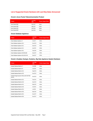
An example of radar penetration of dry soil along the Nile River,Sudan. The Space-borne Imaging Radar (SIR) polarized data revealan ancient, previously unknown channel of the Nile.Space ShuttleColor-InfraredPhotographSIR-C Color Composite: Red C-band HV Green L-band HV Blue L-band HH16
SIR-C/X-SAR Images of aPortion of Rondonia, Brazil,Obtained on April 10, 1994Geometric Relationship Between Two SAR Systems Used forInterferometry to Extract Topographic Information: InSAR17
ShuttleRadarTopographyMission(SRTM)Electrical Characteristics and Relationship with MoistureOne measure of a material's electrical characteristics is thecomplex dielectric constant, defined as a measure of theability of a material (vegetation, soil, rock, water, ice) toconduct electrical energy.Dry surface materials have dielectric constants from 3 to 8 inmicrowave portion of the spectrum.Conversely, water has a dielectric constant of approximately80.The amount of moisture in soil, on rock surface, or withinvegetation tissues may have significant impact on the amountof backscattered radar energy.18
Electrical Characteristics and Relationship with MoistureMoist soils reflect more radar energy than dry soil. Theamount of soil moisture influences how deep the incidentenergy penetrates into materials.The general rule of thumb for how far microwave energy willpenetrate into a dry substance is that the penetration should beequal to the wavelength of the radar system.However,, active microwave energy may penetrate extremelydry soil several meters.Imaging Radar ApplicationsEnvironmental Monitoring Vegetation mapping Monitoring vegetation regrowth, timber yields Detecting flooding underneath canopy, flood plain mapping Assessing environmental damage to vegetationHydrology Soil moisture maps and vegetation water content monitoring Snow cover and wetness maps Measuring rain-fall rates in tropical stormsOceanography Monitoring and routing ship traffic Detection oil slicks (natural and man-made) Measuring surface current speeds Sea ice type and monitoring for directing ice-breakers19
InSAR study of coastal wetlands over southeastern LouisianaZhong Lu, U.S. Geological SurveyOh-ig Kwoun, Jet Propulsion LaboratoryUsing multi-temporal C-band European Remote-sensing Satellites(ERS)-1/-2 and Canadian Radar Satellite (RADARSAT)-1synthetic aperture radar (SAR) data over the Louisiana coastalzone to characterize seasonal variations of radar backscatteringaccording to vegetation types and conduct detailed analysis ofInSAR imagery to study water level changes of coastal wetlands.Chapter 2: In Remote Sensing of Coastal Environment (Wang, Editor), Taylor& Francis, 200920
21
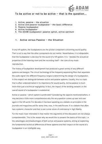
InSAR-derivedwater-level changesInSAR images showing water-levelchanges in coastal wetlands oversoutheastern Louisiana. Each fringe (fullcolor cycle) represents a line-of-sightrange change of 11.8 cm and 2.83 cmfor ALOS and Radarsat-1 interferograms,respectively. Interferogram phase valuesare unfiltered for coherence comparisonand are draped over the SAR intensityimage of the early date. Areas of loss ofcoherence are indicated by randomcolors.M – marshes (freshwater, intermediate,brackish, and saline marshes)L – lakeSF – swamp forestBF – bottomland forestAF – agricultural field22
Advantages of Active Remote Sensing: Sending and receiving EMR that can pass through cloud,precipitation Images can be obtained at user-specified times, even at night. Sending and receiving EMR that can penetrate tree canopy, drysurface, deposits, snow Permits imaging at shallow look angles, resulting in differentperspectives that cannot always be obtained using aerialphotography. Providing information on surface roughness, dielectricproperties, and moisture content.All weather, day-and-night imaging capacity23
LIDAR (LIght Detection And Ranging)Is a rapidly emerging technology for determining theshape of the ground surface plus natural and man-madefeatures.Buildings, trees and power lines are individuallydiscernible features. This data is digital and is directlyprocessed to produce detailed bare earth DEMs at verticalaccuracies of 0.15 meters to 1 meter.Derived products include contour maps, slope/aspect,three-dimensional topographic images, virtual realityvisualizations and more.AS350BA LIDAR Platform24
The LIDAR instrument consistsof a system controller and atransmitter and receiver.receiver. As theaircraft moves forward along thelineline-ofof-flight, a scanning mirrordirects pulses of laser lightacrossacross-track perpendicular to thelineline-ofof-flight.25
Lidar systems generally transmitpulses toward nadir. The lidarpulse is spatially confined toconcentrate energy and getaccurate range estimates.The first and simplest LIDARsystem collects a profile of nearlyequidistant points along thesensor's path.The second technology collectsrange samples within a swath bytransmitting the LIDAR pulsesaway from nadir, effectivelycollecting a "cloud" of data points.LIDAR ReturnsDepending upon the altitude of the LIDARinstrument and the angle at which the pulse issent, each pulse illuminates a nearnear-circulararea on the ground called the instantaneouslaser footprint,footprint, e.g., 30 cm in diameter.This single pulse can generate one return ormultiple returns. All of the energy within laserpulse A interacts with the ground. One wouldassume that this would generate only a singlereturn. However, if there are any materialswhatsoever with local relief within theinstantaneous laser footprint (e.g., grass, smallrocks, twigs), then there will be multiplereturns.26
LIDAR ReturnsPostPost-processing the original data results inseveral LIDAR files commonly referred to as: 1st return;possible intermediate returns;last return; andintensity.The masspoints associated with each return file(e.g., 1st return) are distributed throughout thelandscape at various densities depending uponthe scan angle, the number of pulses persecond transmitted (e.g., 50,000 pps),pps), aircraftspeed, and the materials that the laser pulsesencountered. Areas on the ground that do notyield any LIDARLIDAR-return data are referred to asdata voids.voids.First ReturnLast ReturnBare Earth27
LIDAR-derived TIN Bare Earth DEM overlaid with ContoursClassification ofLandcover basedsolely on LIDARderived Elevation,Slope, andIntensityblue buildingsgreen grasspink vegetation28
LIDAR data can be integrated with other data sets,including orthophotos, multispectral, hyperspectral andpanchromatic imagery.LIDAR can be combined with GIS data and othersurveying information to generate complex geomorphicstructure mapping products, building renderings,advanced three dimensional modeling/earthworks andmany more high quality mapping products.29
1 Active and Passive Remote Sensing Passive remote sensing systems record EMR that is reflected (e.g., blue, green, red, and near-infrared light) or emitted (e.g., thermal infrared energy) from the surface of the Earth. Active remote sensing systems are not dependent