Transcription
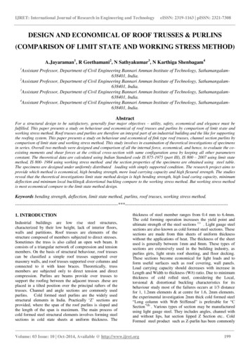
IJRET: International Journal of Research in Engineering and TechnologyeISSN: 2319-1163 pISSN: 2321-7308DESIGN AND ECONOMICAL OF ROOF TRUSSES & PURLINS(COMPARISON OF LIMIT STATE AND WORKING STRESS METHOD)A.Jayaraman1, R Geethamani2, N Sathyakumar3, N Karthiga Shenbagam41Assistant Professor, Department of Civil Engineering Bannari Amman Institute of Technology, Sathamangalam638401, India.2Assistant Professor, Department of Civil Engineering Bannari Amman Institute of Technology, Sathamangalam638401, India.3Assistant Professor, Department of Civil Engineering Bannari Amman Institute of Technology, Sathamangalam638401, India.4Assistant Professor, Department of Civil Engineering Bannari Amman Institute of Technology, Sathamangalam638401, India.AbstractFor a structural design to be satisfactory, generally four major objectives – utility, safety, economical and elegance must befulfilled. This paper presents a study on behaviour and economical of roof trusses and purlins by comparison of limit state andworking stress method. Roof trusses and purlins are therefore an integral part of an industrial building and the like for supportingthe roofing system. This paper presents a study on behaviour and economical of fink type roof trusses, channel section purlins bycomparison of limit state and working stress method. This study involves in examination of theoretical investigations of specimensin series. Overall two methods were designed and comparison of all the internal force, economical, and hence, to evaluate the coexisting moments and shear forces at the critical cross-section with same configuration area by keeping all other parametersconstant. The theoretical data are calculated using Indian Standard code IS 875-1975 (part III), IS 800 – 2007 using limit statemethod, IS 800- 1984 using working stress method and the section properties of the specimens are obtained using steel table.The specimens are designed under uniformly distributed loading with simply supported condition. The research project aims toprovide which method is economical, high bending strength, more load carrying capacity and high flexural strength. The studiesreveal that the theoretical investigations limit state method design is high bending strength, high load caring capacity, minimumdeflection and minimum local buckling& distortional buckling compare to the working stress method. But working stress methodis most economical compare to the limit state method design.Keywords bending strength, deflection, limit state method, purlins, roof trusses, working stress -------------------------------------------1. INTRODUCTIONIndustrial buildings are low rise steel structures,characterized by their low height, lack of interior floors,walls and partitions. Roof trusses are elements of thestructure composed of members subjected to direct stresses.Sometimes the truss is also called an open web beam. Itconsists of a triangular network of compression and tensionmembers. On the basis of structural behaviour, roof trussescan be classified a simple roof trusses supported overmasonry walls, and roof trusses supported over columns andconnected to it with knee braces. Theoretically, trussmembers are subjected only to direct tension and directcompression. Purlins are beams provide over trusses tosupport the roofing between the adjacent trusses .these areplaced in a tilted position over the principal rafters of thetrusses. Channel and angle sections are commonly usedpurlins. Cold formed steel purlins are the widely usedstructural elements in India. Practically „Z‟ sections areprovided, where the span of the roof purlins is sloped andthe length of the span is maximum. The main process ofcold formed steel structural elements involves forming steelsections in cold state sheets at uniform thickness. Thethickness of steel member ranges from 0.4 mm to 6.4mm.The cold forming operation increases the yield point andultimate strength of the steel sections (1) . Light gauge steelsections are also known as cold formed steel sections. Thesesections are made from thin sheets of uniform thicknesswithout the applications of heat. The thickness of the sheetused is generally between 1mm and 8mm. These types ofsections are extensively used in the building industry, aspurlins girts, light struts roof sheeting, and floor decking.These sections become economical for light loads and toform useful surfaces such as roof covering, wall panels.Load carrying capacity should decreases with increase inLength and Width to thickness (W/t) ratio. Due to minimumthickness of cold rolled steel, considering the Local,torsional & distortional buckling characteristics for itsbehaviour study most of the failures occurs at 1/3 distancefor 1, 1.2mm elements & at centre for 1.6, 2mm elements.the experimental investigation 2mm thick cold formed steel“Long column with Web Stiffened” is preferable for “CSection”(2) . Various types of section may be manufacturedusing light gauge steel. They includes angles, channel withand without lips, hat section lipped Z Section etc. ColdFormed steel product such as Z-purlin has been commonlyVolume: 03 Issue: 10 Oct-2014, Available @ http://www.ijret.org199
IJRET: International Journal of Research in Engineering and Technologyused in metal building industry more than 40 year in unitesstate due to their wide range of application, economy, easeof fabrication and high strength-to-weight ratios. Z- Purlinsare predominantly used in light load and medium spansituations such as roof systems (3) 4. The design of industrialbuilding is governed mainly by functional requirements andthe need for economy of construction. In cross-sectionsthese buildings will range from single or multibay structuresof larger span when intended for use as warehouses oraircraft hangers to smaller span buildings as required forfactories, assembly plants, maintenance facilities, packingplants etc. The main dimensions will nearly always bedictated by the particular operational activities involved, butthe structural designer‟s input on optimum spans and theselection of suitable cross-sections profile can have animportant bearing on achieving overall economy. An aspectwhere the structural designer can make a more directcontribution is in lengthwise dimensions i.e. the bay lengthsof the building. Here a balance must be struck betweenlarger bays involving fewer, heavier main components suchas columns, trusses, purlins, crane beams, etc. and smallerbays with a large number of these items at lower unit mass.An important consideration in this regard is the cost offoundations, since a reduction in number of columns willalways result in lower foundation costs. Light gauge coldformed steel section channel section have high bendingstrength, high load caring capacity, minimum deflection andminimum local buckling & distortional buckling compareto the built up channel section by same cross sectional area.The numerical investigation of channel section is themaximum bending moment, torsional moment anddeformation is higher than the built up channel section bysame cross sectional area(4). There are several failure modesamong which distortional buckling is one such failure modethat affects the strength of the section. In order to assess theinfluence of distortional buckling, a parametric study hasbeen conducted by varying the lip depth, which is theinfluencing factor for distortional buckling strength (5).Channels may be used as compression or flexural members.Hat section and Z section are used as flexural members.Hollow rectangular section used for variety of sections.Built up I section using Light gauge steel with lower H/taspect ratio behaves significantly showing elastic and plasticdeformation both. With increment in H/t aspect ratio thisbehaviour changes and shows failure in elastic zone (6).Black bolts and high strength friction grip bolts may be usedfor the connection of the light gauge sections. However,high strength friction grip bolts are most suitable for theconnection of light gauge sections. Advances incomputational features and software have brought the finiteelement method within reach of both academic research andengineers in practice by means of general-purpose nonlinearfinite element analysis packages, with one of the most usednowadays being ANSYS. The program offers a wide rangeof options regarding element types, material behaviour andnumerical solution controls, as well as graphic userinterfaces (known as GUIs), auto-meshers, and sophisticatedpostprocessors and graphics to speed the analyses. In thispaper, the structural system modelling is based on the use ofthis commercial software. Several numerical modellingeISSN: 2319-1163 pISSN: 2321-7308issues related to potential convergence problems, loadingstrategies and computer efficiency. The accuracy andsimplicity of the proposed model make it suitable to predictand/or complement experimental investigations (7) .most ofstructural elements are analysis by using STADD pro andANSYS.2. AIM OF THE STUDYThe main aim of the study provides which method is mosteconomical method and , high bending strength, more loadcarrying capacity and high flexural strength by analysis ofboth working stress and limit state method.3 .EXPERIMENTAL INVESTIGATION3.1 Materials3.1.1 Light Gauge Steel Physical Properties:The rolled steel sheet is used. The physical properties oflight gauge steel section given in Table 1.The propertiestaken from the Indian Standard code IS 800-2007Table 1 Physical properties light gauge steel sectionDensity of steel ( ᵨ )7850 kg / m3Modulus of elasticity ,E2 x 105 N / mm2Poisson ratio0.3Modulus of rigidity , G0.769 x 10 5 N / mm2CO efficient of thermal 12 x 10-6expansion (α )3.1.2 Components of Roof Trusses:Principal rafter, sling, principal tie, strut, tie, bottom chordand top chord purlins, sag tie and bracingVolume: 03 Issue: 10 Oct-2014, Available @ http://www.ijret.org200
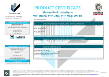
IJRET: International Journal of Research in Engineering and TechnologyeISSN: 2319-1163 pISSN: 2321-7308Fig 1 Components of roof trusses3.1.2.1principal Rafter3.1.3.1 Dead Load:Principal rafter is a post chord member in a roof truss andboom is the principal compression member in arcane.The dead loads of the truss include the dead load of roofingmaterials, purlins, trusses and bracing system.3.1.2.2 Stanchion3.1.3.2 Live Load:Column, stanchion or post is a vertical compression membersupporting floors or girders in a building. Thesecompression members are subjected to heavy loads.The imposed load on sloping roofs with slops up to andincluding 10 degree is to be taken as 0.75kN/m2 of plan area.for roofs with slopes 10degree,an imposed load0.75kN/m2 0.02 kN/m2 for every degree increase in slopeover 10 degree ,subject to a minimum of 0.4 kN/m2 is to betaken for roof membrane.3.1.2.3 StrutStrut is a compression member used in the roof truss andbracing. It is small span and lightly loaded compressionmember. A strut may be continuous or discontinuous. Acontinuous strut is a compression member which iscontinuous over a number of joints, such as a top chordmember of a truss bridge girder, principal rafter of a rooftruss etc.3.1.3.3 Snow Load:This load various with the region in which the structure isbuilt. Actual load due to due to snow will depend upon theshape of the roof and its capacity to retain the snow. In caseof roofs with slope greater than 50 degree, snow load maybe disregarded.3.1.2.4 PurlinsPurlins are beams provide over trusses to support the roofingbetween the adjacent trusses .these are placed in a tiltedposition over the principal rafters of the trusses. Channeland angle sections are commonly used purlins3.1.3.4 Wind Load:The most critical load on an industrial building is the windloadWind force (F) (Cpe – Cpi) A Pd3.1.2.5 Sag Tie:The long middle tie member of the truss may sag because ofits self weight and to check this sag tie may be provided.3.1.3 Loads on the Roof Truss:roof truss are subjected to dead load, live load, wind loadand snow loads etc.3.1.4 Spacing of Roof Trusses:the usual economical spacing ranges between 4 and 8m withthe lower limit for short truss spans and higher limit for longspans of about 30 m or over. For span upto 18m spacingshould preferably be 4m but not exceed 5m. For spans from18m to 25m the spacing should not exceed 6m.in our casethe spacing of trusses is limited to 6m.Volume: 03 Issue: 10 Oct-2014, Available @ http://www.ijret.org201
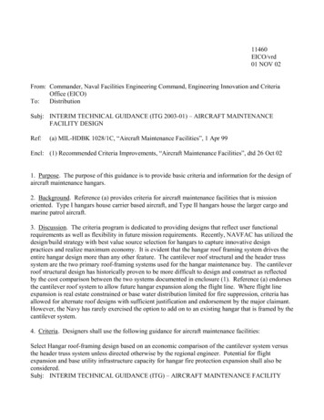
IJRET: International Journal of Research in Engineering and TechnologyeISSN: 2319-1163 pISSN: 2321-73083.2 Theoretical Investigations of Roof Trusses andPurlins3.2.1 Design of Roof TrussesThe building is located in industrial area Coimbatore. Bothends of the truss are hinged.Span of the roof truss is 18mSpacing of the trusses is 4mHeight of building is 8mLength of buildings is 20mRise of the trusses 1 in 4Pitch of the roof trussesPitch (p) 𝑑𝑒𝑝𝑡 𝑠𝑝𝑎𝑛 )Fig 2 Dead load at panel points 4.5m3.2.1.2 Design of Live Load:Slope of the roof (ϴ ) 26.56The live loads are taken from the steel table and IS 875 –1975Length along the slopping roof 10.06mLength of each panel let us divide the length in to four equalparts length of each panelLength of each panel 𝑙𝑒𝑛𝑔𝑡 𝑜𝑓 𝑠𝑙𝑜𝑝𝑝𝑖𝑛𝑔 𝑟𝑜𝑜𝑓4 418 N/m2Live load 750 – 20 x (26.56 – 10 )Load at each intermediate panel due to live load 3800 NLoad at each end panel due to live load 1900 N 2.52 mLoad calculation3.2.1.1 Design of Dead Load:The dead loads are taken from the steel table. The deadloads of the truss include the dead load of roofing materials,purlins, trusses and bracing systemWeight of roof covering (galvanised sheeting) 150 N /m2Weight of purlins 100 N/m2Weight of wind bracing 15 N/m2Self Weight of trusses (span / 3 5)10 110 N/m2Total dead load of roof trusses (Wd) 375 N/m2Load at each intermediate panel due to dead load 3375 NLoad at each end panel due to dead load 1687.5 NFig 3 Live load at panel points3.2.1.3 Design of Wind Loads:Let us assume industrial building to be 50 years and the andthe land to be plain and surrounded by small buildings.Risk coefficient (k1) taken from IS 875- 1975of building 50 years)Terrains category (k1) taken from IS 875- 1975 1 (life 0.88Topography factor (k3) taken from IS 875- 1975 1 (plainground)Basic wind speed (Vb) for zone 5Design wind speed (Vz) k1 x k2 x k3 x VbDesign wind pressure Pd (0.6 x Vz 2) 39 m / s 34.44 N /m2 711.66 N /m2Volume: 03 Issue: 10 Oct-2014, Available @ http://www.ijret.org202
IJRET: International Journal of Research in Engineering and TechnologyAn internal pressure coefficient depends upon the degree ofpermeability of cladding to the flow of air. The internal airpressure may be positive or negative depending on thedirection of flow of air in relation to opening in the building.Building with small opening 0-5% the an internal pressurecoefficient 0.2 or -0.2, Building with medium opening 5 –20 % an internal pressure coefficient 0.5 or -0.5 ,Building with large opening above 20 % an internalpressure coefficient 0.7 or -0.7 .eISSN: 2319-1163 pISSN: 2321-7308Bending moment in y-y direction Mdy0.279 kNm 𝑤𝑑 𝑥 𝑠𝑖𝑛𝛳 𝑥 𝐵Bending moment in wind direction Mwx 3.44 kNm10 𝑤𝑤 𝑥 𝐵10An internal pressure coefficient 0.5 or -0.5 because ofbuilding with medium opening 5 – 20 m. An externalpressure coefficient 0.7 or -0.7 depends upon the heightand width ratio wind ward and lee ward given in conditionIS 875 -1975. Part IIIWind force (F) (Cpe – Cpi) x A x Pd 8160 NLoad at each intermediate panel due to wind load3800 NLoad at each end panel due to wind load 1900 NWhereB Spacing of the trussWd dead load, ww wind loadMaximum Design moments Mxx Mdx Mwx 2.90kNmSection modulus (Z) required 𝑀𝑋𝐵𝑒𝑏𝑑𝑖𝑛𝑔 𝑠𝑡𝑟𝑒𝑠𝑠 ( 0.66 𝑥 250 ) 0.27kNmSelection of channel section 40% more than the actualsection modulus. There foreLet us provide ISMC 100 @ 92 N/m, A 1170mm2Fig 3 Wind load at panel points3.2.2 Theoretical Investigations of Purlins byWorking Stress MethodPurlins section is subjected to biaxial bending by dead loadand uniaxial bending by wind load, such bending is calledunsymmetrical bending. Purlins may be designed as simple,continuous or cantilever beams. The simple beam designyields the greatest moments and deflections. The bendingmoment due to dead load and wind load areBending moment in x-x direction Mdx0.54 kNm 𝑤𝑑 𝑥 𝑐𝑜𝑠𝛳 𝑥 𝐵10 Relevant Properties of channel section Zxx 37.3 x 103mm3, Zyy 7.5x 103 mm3Check for bending stresses /mm𝑀𝑥𝑥𝑍𝑥𝑥 𝑀𝑦𝑦𝑍𝑦𝑦 137.74 N2Volume: 03 Issue: 10 Oct-2014, Available @ http://www.ijret.org203
IJRET: International Journal of Research in Engineering and TechnologyeISSN: 2319-1163 pISSN: 2321-7308The actual bending stress is 165 N /mm2 and design bendingstress is 137.74 N /mm2(Z) Required 62.76 x103 mm3Hence section is safe 137.74 N /mm2 165 N /mm2Selection of channel section 40% more than the actualsection modulus. There fore3.2.3 Theoretical Investigations of Purlins by LimitLet us provide ISMC 150 @ 164 N/mState MethodLimit state methodDead load 375 N/m2Wind load 8160NThe component of dead load parallel to the roof 375 x2.52 x sin 26.56The component of dead load normal to the roof2.52 x cos 26.56Total load on purline normal to the roof 375 x 13085.27 N/mFactored load normal to the roof (p) 19627.905 N/mFactored load parallel to the roof (p) 633.8 N/mThe limit state method normal and parallel to the roof loaddiagram given belowArea 1836mm2, Moment of inertia Ixx 697.2 x 104 mm4,Iyy 103.2 x 104 mm4,Elastic section modulus Zez 93 x 103 mm3Plastic section modulus Zpz bf x tf (h- tf) tw (h – 2 tf /4) 83.34 x103 mm3Design bending capacity of the section Mdz 1.2 x Zez x (fy𝛾𝑚𝑜Zpzx(fy𝛾𝑚𝑜))Mdz 18.94 x 10⁶ Nmm 23 .94 x 106 NmmThe actual bending moment is 12.157 kNm and designbending capacity is 18.94 x 10⁶ N/mm 2, hence section is safe18.94 x 106 12.157 kNm4. RESULT AND DISCUSSIONMaximum bending moment in x- x direction12.157 kNm 𝑃𝐿 10Maximum bending moment in y-y direction 12.157 kNm 𝐻𝐿10Required plastic section modulus (Z) required let us try todepth of the section 300 mm and width of flange 90 mm𝐷𝑒𝑝𝑡 𝑜𝑓 𝑡 𝑒 𝑠𝑒𝑐𝑡𝑖𝑜𝑛𝛾𝑚𝑜(Z) Required 2.5 () x (My ()width of the flangefyOverall two methods were designed and comparison of allthe internal force, and hence, to evaluate the co-existingmoments and shear forces at the critical cross-section withsame configuration area by keeping all other parametersconstant. The theoretical data are calculated using IndianStandard code IS 800-1984 using working stress method, IS800-2007 using limit state method, steel table and IS875part (III) using calculation of wind load recommended.The theoretical results of the limit state method is bendingmoment and load caring capacity is 76.25 % and 41.35 %higher than the working stress method. Actual deflectionand bending stress is same in both the method. But workingstress method is more economical method compare to thelimit state method. The working stress method, the totalweight of steel is required 1502 kg and total rate of cost isRS 82,610. The limit state method the total weight of steel isVolume: 03 Issue: 10 Oct-2014, Available @ http://www.ijret.org204
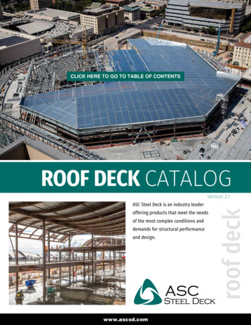
IJRET: International Journal of Research in Engineering and Technologyrequired 2308 kg and total rate of cost is RS 126,940. In thispaper investigation, the limit state method is the totalquantity of weight of steel and rate of cost is 34.78% highereISSN: 2319-1163 pISSN: 2321-7308than the working stress method. Comparison of rate of theamount for panel length of truss and spacing of truss givenin table belowTable 2 Comparison of Weight and Amount by Working stress method and Limit state method for Spacing of the TrussSpacing of the Limit state methodWorking stress methodtruss in (m )Weight in (kg)Amount (RS)Weight in (kg)Amount 8520m288.515853.75187.7510106.25Comparison of weight and amount by working stressmethod is 36.75 kg and RS 3170.25 centre to centre spacingof the truss and Limit state method is centre to centreSpacing of the truss 57.65 kg and rare of the amount is RS2021.25. The result are shown in table .2 and given in figure4.Fig 4 cost between WSM & LSM spacing of TrussTable 3 Comparison of Weight and Amount by Working stress method and Limit state method for panel length of the TrussPanel length in ( m )Limit state methodWorking stress methodWeight in (kg)Amount (RS)Weight in (kg)Amount 283.75182306126830150282610Comparison of weight and amount by limit state method is288.5 kg and RS 15867.5 for per panel length and 20 mlength of truss and working stress method is 187.75kg andrare of the amount is RS 10326.25. The result are shown intable .3 and given in figure 5.Volume: 03 Issue: 10 Oct-2014, Available @ http://www.ijret.org205
IJRET: International Journal of Research in Engineering and TechnologyeISSN: 2319-1163 pISSN: 2321-7308Fig 5.cost between WSM & LSM panel length of the TrussComparison Between WSM & LSM Weight ratio perpanel length2500Weigyt in 18Panel length in mFig 6 cost between WSM & LSM spacing of Truss5. CONCLUSIONSIn this paper investigation the total roofing loadconfiguration is same in both the working stress and limitstate method. But area of section is 37% needed for limitstate method in compare to the working stress method.The theoretical results of the limit state method is bendingmoment and load caring capacity is 76.25 % and 41.35 %higher than the working stress method. Actual deflectionand bending stress is same in both the method. But workingstress method is more economical method compare to thelimit state method. The working stress method, the totalweight of steel is required 1502 kg and total rate of cost isRS 82,610. The limit state method the total weight of steel isrequired 2308 kg and total rate of cost is RS 126,940. In thispaper investigation, the limit state method is the totalquantity of weight of steel and rate of cost is 34.78% higherthan the working stress method. The studies reveal that thetheoretical investigations limit state method design is highbending strength, high load caring capacity, minimumdeflection and minimum local buckling& distortionalbuckling compare to the working stress method. Butworking stress method is cost wise most economical methodcompare to the limit state method design.The studies reveal that the theoretical investigations limitstate method design is high bending strength, high loadcaring capacity, minimum deflection and minimum localbuckling& distortional buckling compare to the workingstress method. But working stress method is mosteconomical compare to the limit state method design.Volume: 03 Issue: 10 Oct-2014, Available @ http://www.ijret.org206
IJRET: International Journal of Research in Engineering and TechnologyeISSN: 2319-1163 pISSN: n.A,Dr.Baskar.G(2013)“Experimental study on cold formed steel purlinsections” Engineering Science and Technology: AnInternational Journal (ESTIJ), ISSN: 2250-3498,Vol.3, No.2, April 2013 276M.Meiyalagan,M.AnbarasuandDr.S.Sukumar.(2010) “Investigation on Cold formedC section Long Column with Intermediate Stiffener& Corner Lips – Under Axial Compression.”International journal of applied engineeringresearch, dindigul , Volume 1, No1, 2010Govindasamy.P, Sreevidya .V, Dr.L.S.Jayagopal“Comparative Study on Cold Form Purlins forDistortional Buckling Behaviour” internationaljournal of engineeringsciences & researchTechnology ISSN: 2277-9655Sunil. M.Hardwani, A.V.Patil (2012) “Study, testand designing of cold formed Section as per AISIcode.” Int. Journal of Applied Sciences andEngineering Research Vol. 1, Issue 3, 2012.Sanchita.S.Nawale, Sangram Chalukya, andDr.S.V.Admane “Comparative Analysis andBending Behavior of Cold form Steel with HotRolled Steel Section.” American Journal ofEngineering Research (AJER) e-ISSN : 2320-0847p-ISSN : 2320-0936 Volume-03, Issue-05, pp-255261(2013)P. P. Desai and M. R. Shiyekar (2014) “LimitStrength Prediction of Light Gauge Steel I Sectionby Finite Element Method.” Int. Journal ofEngineering Research and Applications, ISSN :2248-9622, Vol. 4, Issue 7( Version 4), July 2014,pp.111-114 (2014)F.D. Queiroza , P.C.G.S. Vellascob and D.A.Nethercota (2007) “Finite element modelling ofcomposite beams with full and partial shearconnection” Journal of Constructional SteelResearch 63 (2007) 505–521 Received 25 January2006; accepted 8 June 2006Volume: 03 Issue: 10 Oct-2014, Available @ http://www.ijret.org207
Purlins are beams provide over trusses to support the roofing between the adjacent trusses .these are placed in a tilted position over the principal rafters of the trusses. Channel and angle sections are commonly used purlins 3.1.2.5 Sag Tie: The long middle tie member of the truss may sag because of