Transcription
RoofStructureDesignGuidePatrick A. Bodwell
Roof Structure Design GuidePatrick A. BodwellVerco Decking, Inc.
Copyright 2021 by Verco Decking, Inc. All rights reservedPublished by Verco Decking, Inc. Phoenix, Arizona.No part of this publication may be reproduced, stored in a retrieval system, or transmitted in any form or byany means, electronic, mechanical, photography, recording, scanning, or otherwise, except as permittedunder Section 107 or 108 of the 1978 United States Copyright Act, without the prior written permission of thePublisher. Requests to the publisher should be directed to Verco Decking Inc., 4340 N 42nd Ave, Phoenix, AZ85019, or through vercodeck.com.
AcknowledgmentsThis design example is the culmination of more than a decade of effort to document a set of best practicesbased on conversations with steel fabricators, erectors, contractors, and engineers. Many great professionalshave contributed suggestions to create the most economical solutions to solve critical design questions.This could not have been accomplished without the input from two talented engineers, Rao Nunna, S.E. withS.B. Barnes Associates, and John Whiteman, S.E. with Vulcraft, who provided review of the drafts that led tothis product. John went on to offer his experience from 17 years of practice at a structural engineering firmspecializing in warehouse design to create the plans, notes, schedules, and details in the Appendix. Many ofmy Vulcraft and Verco teammates spent tedious hours checking the math and helping with countless editorialimprovements to my writing. I do not have adequate words to express the gratitude to all of those who put somany hours in to help me get this to the finish line.DisclaimerDesign defects that could cause injury or death may result from relying on the information in this documentwithout independent verification by a qualified professional. The information in this document is provided “ASIS”. Nucor Corporation and its affiliates expressly disclaim: (i) any and all representations, warranties andconditions and (ii) all liability arising out of or related to this document and the information in it.NUCOR, VULCRAFT, VERCO, and FORMLOK are registered trademarks of Nucor. QuickFrames is atrademark of QuickFrames USA. Chicago Clamp is a registered trademark of Chicago Clamp Company.V2021
Table of Contents1.0 Introduction1.1. Design Example1.2. Cold-Formed Steel Deck Calculations1.3. Codes and Reference Documents2.0 Warehouse Building2.1. Dead Loads2.2. Deflection Criteria2.3. Seismic and Wind Parameters3.0 Building Size Limitations3.1. Area and Height Limits for Fire and Life Safety3.2. Height Limits for Structural Seismic Design4.0 Steel Deck Vertical Load Design4.1. Steel Deck Out-Of-Plane Design4.2. Open Web Steel Joist (OWSJ) Vertical Load Design4.3. Open Web Steel Joist Girder Vertical Load Design5.0 Seismic Diaphragm Design5.1. Seismic Force Development5.2. Diaphragm Force Coefficient5.3. Roof Diaphragm Shear Load5.4. Skylight or Smoke Hatch Considerations5.5. Steel Deck Diaphragm Shear Design5.6. Diaphragm Chords5.7. North-South Diaphragm Deflection and P-Delta Effects5.8. East-West Diaphragm Deflection6.0 Seismic Wall Anchorage, Ties, and Sub-Diaphragms6.1. Wall Anchorage Force6.2. Steel Roof Deck Wall Anchorage Design and Continuous Ties6.3. Open Web Steel Joist Wall Anchorage Design and Continuous Ties7.0 Wind Diaphragm Design7.1. Main Wind Force Resisting System Loads7.2. Load Combinations7.3. Diaphragm Shear Wind Loading7.4. Skylight and Smoke Hatch Considerations7.5. Wind Diaphragm Design7.6. Wind Diaphragm Chord Design7.7. Wind Diaphragm Deflection8.0 Wind Wall Anchorage and Ties8.1. Wind Loads on Walls8.2. Loads Combinations8.3. Wall Bracing with Steel Roof Deck8.4. North-South Wall Bracing with Open Web Steel 01101104105110110115116119119121121124
9.0 Factory Mutual9.1. Factory Mutual Data Sheets9.2. Fire Rating9.3. Steel Roof Deck Approval9.4. FM Wind Design Pressure9.5. Steel Roof Deck Design for Wind Uplift9.6. FM Steel Deck Securement to Support Framing9.7. FM Steel Roof Deck Schedule10.0 Very Large Warehouse Structures10.1. Thermal Expansion10.2. Large Single Diaphragm Design10.3. High Shear Large Diaphragms with Interior Brace Frames10.4. Example Large Project Successes11.0 Skylights, Smoke Hatches, Roof Top Mechanical Units, and Misc. Roof Penetrations11.1. Skylights and Smoke Hatches11.2. Roof Top Mechanical Units Support Frames11.3. Roof Top Mechanical Unit Design Example11.4. Miscellaneous Steel Roof Deck PenetrationsAppendixPlans and 61162163176181
1.0 IntroductionSteel roof deck and open web steel joist is the predominate roof system in the United States for large flat roofstructures. This system is the preferred choice of developers for its simplicity, strength, fire resistance, andeconomy. Large distribution warehouses, big-box retail, industrial and single-story commercial buildings allbenefit from a steel deck and joist roof structure.This steel roof deck and joist design example offers guidance for the design professional based on currentbest practices in order to provide the best possible safe and economical steel roof deck and open web steeljoist roof structure. The combinations of products illustrated in this example may not be the optimum for everyproject, however the underlying methods provide a basis to optimize many other combinations of steel roofdeck and joists.1.1 Design ExampleThe design example walks through the design of a modest 300 ft x 504 ft warehouse structure starting withbasic fire life-safety and continuing through the structural design of the steel roof deck and open web steeljoists and girders. The seismic design of the diaphragm and wall anchorage are followed by a wind loadanalysis to ensure that the building design based on seismic requirements is capable of resisting the windloading. The resulting design is summarized as a set of roof structural plans, notes, schedules, and details inthe Appendix.Factory Mutual roof assembly considerations are applied to the example building to demonstrate the impact ofFactory Mutual compliance on the design. Factory Mutual applies wind load conditions and detailing that goesbeyond the minimum life-safety requirements of the building code, with the goal of mitigating property loss.Very large roof structures require additional design considerations to distribute the design loads and accountfor the effects of thermal expansion. The design methods used for the modest design example structureare applied to very large roof structures in combination with consideration of thermal expansion. This willdemonstrate that thermal expansion joints may be eliminated in many large roof structures through the use ofa ductile steel roof diaphragm system. The elimination of thermal expansion joints in the diaphragm simplifiesthe design process, while providing a safer and more efficient building.1.2 Cold-Formed Steel Deck CalculationsThe design example takes advantage of both Verco and Vulcraft web-based design tools to determine thestrength of the steel roof deck and open web steel joist tie plates. These web-based solutions are a large stepforward from the catalogs of static load tables historically used for the design of steel roof deck. Summarydesign tool output tables are inserted in the design example where steel deck strength is required. Readersare encouraged to utilize the web-based design tools referenced throughout the design example to minimizedesign effort and maximize project economy by creating project specific product data sheets for their next roofstructure design.1.3 Codes and Reference DocumentsThis example follows the provisions of the International Building Code and referenced standards in force at thetime of writing. In addition, the Verco IAPMO-UES product evaluation report is used as the basis of recognitionfor proprietary products and design methods. The primary reference documents used are:International Building Code (2018 IBC)American Society of Civil Engineers, Minimum Design Loads for Buildings and Other Structures (ASCE7-16)American Iron and Steel Institute North American Specification for the Design of Cold-formed SteelStructural Members (AISI S100-16)Wind Design, 2015 Interim Revision February 2020 (FM 1-28)1
Roof Deck Securement and Above-Deck Roof Components January, 2016 Interim Revision February2020 (FM 1-29)Approval Standard for Profiled Steel Panels for Use as Decking in Class 1 Insulated Roof Construction,June 2012 (Class Number 4451)Verco Decking, Inc. IAPMO-UES Evaluation Report (ER-2018))Steel Deck Institute Standard for Steel Roof Deck (RD-2017)Steel Deck Institute Manual of Construction, 3rd Edition (MOC3, 2016))Steel Joist Institute Standard Specifications, 44th Edition (SJI 100-2015)2
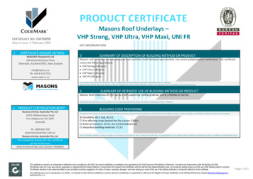
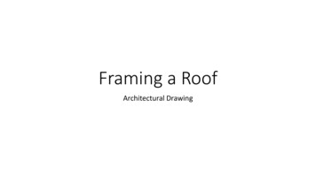
2.0 Warehouse BuildingThis design guide addresses a typical mid-sized warehouse building, with concrete tilt-up walls, tube steelcolumns, open web steel joists & joist girders, and a steel deck roof diaphragm. The principles applied tothe design of the roof deck for this structure have direct parallels with similar buildings constructed with offsite pre-cast wall panels, concrete unit masonry walls, and steel (brace) frame systems. The building can besummarized as follows:Building Use:Warehouse/rack storage and/or manufacturing with optional office space.Roof Structure:Steel Roof Deck supported by open web steel joists and open websteel joist girders bearing on concrete tilt-up panels and tube steelcolumns with a minimum 1/4 inch per foot slope to mitigate pondingconsiderations.Wall Structure:Cast on-site concrete tilt-up wall panels.Seismic Force Resisting System:Intermediate precast shear walls (bearing wall system, Reference A5 inASCE 7 Table 12.2-1) supporting a flexible steel roof deck diaphragm.Fire Protection System:Automatic sprinkler system.Site Conditions:60 foot side-yard clearance on all four sides of building.Figure 2.1 Warehouse BuildingThe warehouse building is based on bay sizes and framing layouts that have been proven to provide aneconomical balance of structural performance while providing efficient joist spacing for the automatic firesprinkler systems. The bay size for this example warehouse is 50 ft x 56 ft. The 50 ft long open web steeljoists are spaced at a uniform 8 feet o.c. across the building, bearing on the 56 ft long open web steel joistgirders. The roof height ranges from 32 ft to 36 ft with a 37 ft parapet height.3
Figure 2.2 Warehouse Building Plan ViewFigure 2.3 Warehouse Building Cross Section2.1 Dead LoadsRoof Structure Dead Load:Roofing System re-roof (3 psf 2 psf)5.0 psfSteel deck3.0 psfSubtotal for Steel Deck and Roofing SystemAutomatic Sprinklers2.0 psfMiscellaneous1.5 psfOpen Web Steel joists2.0 psfSubtotal for Open Web Steel JoistsOpen Web Steel Joist Girders13.5 psf1.5 psfTotal Dead Load48.0 psf15.0 psf
Roof Structure Live LoadUniform Roof Live load20.0 psf (reducible)Concentrated Live Load300 lbs (over a 2.5 ft x 2.5 ft area)Snow LoadDoes not apply at this siteWall Dead LoadNormal Weight Concrete150 pcfWall Thickness9¼ inchWall Weight116 psf2.2 Deflection CriteriaBuilding deflection is primarily a serviceability consideration. Deflections are limited for warehouse typestructures to prevent damage to non-structural elements of the structure.The roof structure deflection is due to vertical gravity and wind loads. IBC Table 1604.3 allows for roofstructures not supporting a ceiling to deflect up to L/180, however it requires a more stringent L/240 for roofmembers supporting non-plaster ceilings. Many warehouse structures end up with a portion of the buildingcontaining office space with a ceiling. For this reason, a L/240 deflection limit will be set for the joists andgirders that may support the future ceiling and the more liberal L/180 for the steel deck that will not support theweight of the future ceiling.MemberJoists & GirdersSteel DeckLive Load Deflection LimitL/240L/180Wind Load Deflection LimitL/240L/180Seismic lateral deflection, building drift, is primarily a structural consideration. When a structure is subject tothe design level earthquake it is acceptable for there to be damage to nonstructural elements of the structure,provided that life safety is not compromised. The primary deflection requirement is to limit the shear deflectionof the diaphragm to prevent a progressive collapse of the primary structure. To prevent collapse, the P-deltastability coefficient will not exceed 0.10 following the requirements of ASCE 7 Section 12.8.7.PΔ limit0.10Lateral wind deflection is service level deflection criteria similar to vertical loads. The IBC does not providea specific requirement. Guidance may be taken from ASCE 7 Appendix Commentary Section CC.2.2 thatrecommends that a vertical deflection limit between L/600 and L/400 is generally an acceptable range for moststructures. For this warehouse structure, the more liberal L/400 deflection limit will be set.Wind Diaphragm Deflection LimitL/4005
2.3 Seismic and Wind ParametersOntario, California is the location selected for this design example. The following seismic and wind parametersare for this location. These parameters are discussed further in Sections 5 and 6.Seismic ParametersSs 1.5g (short period)S1 0.6g (1-second period)Risk Category IISite Class DWind ParametersV 95 mph basic wind speedKd 0.85 Wind directionality factorKzt 1.0 Topographic FactorKe 1.0 Topographic FactorRisk Category IIExposure Category CEnclosure Classification Enclosed6
3.0 Building Size LimitationsBuilding area and height limits have been established for all building types to ensure basic life safety in thedesigns. The requirements are set forth in the provisions of the IBC for general occupancy egress and fireconsiderations. ASCE 7 also includes limitations for life safety in seismic events based on the lateral systemused.3.1 Area and Height Limits for Fire and Life SafetyThe IBC limits the area and height of a building based on a combination of the occupancy type, fire resistancefor the building materials and the fire protection system. The common occupancy types that this examplebuilding would fall under are storage (warehouse) and/or manufacturing. In addition, a portion of the building islikely to have business (office) usage. Mercantile (retail) often use this same building type.The last factor to consider to determine the fire and life safety requirements for the structure is whether or notautomatic fire sprinklers are used for fire suppression in the building. The building that is part of this exampledoes have an automatic fire sprinkler system.The occupancy category is determined in accordance with Chapter 3 of the IBC.The following possible occupancies have been identified for this example:Moderate Hazard Storage Group S-1IBC §311.2Moderate Hazard Factory Group F-1IBC §306.2Business Group BIBC §304.1Mercantile Group MIBC §309.1For this example, all of the primary structural members are non-combustible by nature, including the concretewalls, steel columns, steel joists and steel deck. However, in the installed condition without a fire proofingcoating, the steel does not meet the requirements for a fire rated assembly, therefore it qualifies for a Type II-Brating.Fire Resistance Rating Type II-BIBC §602.2 & Table 601Based on the fire resistance rating Type II-B and occupancy categories B, F-1, M, and S-1, the followingbuilding limitations are established:55 ft maximum height, not sprinkleredIBC Table 504.375 ft maximum height, sprinklered (controls for this example building)The clearances around the building will also impact the allowable building area. For this example building,there is 60 foot side yard clearance on all 4 sides of the building.1-story with automatic sprinklers and 60 foot public ways or yards, Groups B, F, M or S:Unlimited Area (controls for this example building)IBC per §507.42-story with automatic sprinklers and 60 foot public ways or yards, Groups B, F, M or S:Unlimited AreaIBC per §507.57
The warehouse building in this example is checked to determine if it meets the fire and life safety limitations ofthe IBC in Section 504.3. The building height is measured from grade to the average roof height. In this casethe floor level will be assumed to be 4 ft above grade for loading docks around the warehouse perimeter with a34 ft average roof height above the floor level. See Figure 2.3 Building Cross Section depicting the elevationof the roof structure relative to the floor level.Area:504 ft x 300 ft 151,200 sf Unlimited area, therefore acceptableHeight:34 ft 4 ft 38 ft 75 ft, therefore acceptableStories:1 1 or 2 stories for unlimited area, therefore acceptableChapter 5 of the IBC provides the complete requirements for maximum area, height, and number of stories forbuildings that do not meet the requirements for an unlimited area building.3.2 Height Limits for Structural Seismic DesignThe determination of the building height for seismic life safety design is different than that for fire and lifesafety design in the IBC. For seismic design the height is taken from the base of the structure to the top ofthe seismic force resisting system. ASCE 7 defines the base of the structure as “the level at which horizontalseismic ground motions are considered to be imparted on the structure”. The common convention is to tie thewall panels into the concrete floor slab. The floor slab therefore defines the elevation at which the seismic loadis transferred into the building.The Seismic Design Category (SDC) assigned to the building is a primary limiting factor of the maximumbuilding height. This warehouse structure with intermediate precast shear walls, bearing wall system as theseismic force-resisting system, will typically be assigned a SDC of D or higher in high seismic regions. Thedetermination of the SDC is covered in Section 5 of this example. For structures with a SDC of D or higher themaximum building height is limited to 40 feet in ASCE 7 Table 12.2-1. There is an allowance made in Footnotei of the table, increasing the height to 45 feet for single story storage warehouse facilities. The increased 45 ftlimit allowance for warehouse structures is within the height limits for storage buildings with Early SuppressionFast Response (ESFR) sprinkler systems.Height:834 ft 45 ft, therefore acceptableASCE 7 Table 12.2-1(A5)
4.0 Roof Structure Vertical Load DesignSteel roof structures support vertical loads including dead loads including the self-weight of the roof structure,fire sprinkler systems, miscellaneous mechanical/electrical systems, roof live loads, and wind loads. The roofstructure may also support snow loads, depending on building location, although that is not applicable to thisexample building located in Southern California. The load resisted by each member of the roof structure willvary based on the load combination it supports. The steel deck will support its self-weight, the roof assembly,roof live load, and wind load. The open web joist girders support the loads imposed by the steel deck inaddition to their self-weight, mechanical systems, fire sprinkler system, and architectural finishes such asceilings.The load to each member can be determined using load combinations from one of two methods, AllowableStress Design (ASD) or Load and Resistance Factor Design (LRFD). This example uses the ASD loadcombinations in ASCE 7-16 Section 2.4.1 for the vertical design. The governing load combinations are thenused to help determine the appropriate steel deck type and gage and deck fastening system. The loadcombinations will also be used to specify the appropriate open web steel joists and joist girders.4.1 Steel Deck Vertical Load DesignThe design of steel deck to support vertical loads has several parts that include developing the design loads,checking the strength of the steel deck, and checking deflection for serviceability. This involves determiningthe dead load, the appropriate live load, calculating the wind loads, and determining the governing loadcombinations.The steel deck provides vertical support for the weight of the roof system, roof live loads, and wind loads.For this warehouse building example, the steel deck will not be used to support the miscellaneous ceiling,mechanical, electrical, and fire sprinkler system loads. The various miscellaneous loads mentioned abovewill be supported by the open web steel joists, open web steel joist girders, and miscellaneous steel memberswhen needed. The design of the deck to resist in-plane seismic or wind driven diaphragm shear loads isaddressed in Sections 5 and 7 respectively.Figure 4.1 Vertical Uniform LoadingThe steel deck panels support the uniform vertical dead and live load. The panels act as a series of beamsspanning between the open web steel joist framing. The resolution of forces on the steel deck is developedusing engineering mechanics for a slender simple or multi-span beam as shown in Figure 4.2.9
Figure 4.2 Uniform Load Reactions at Supports for 1, 2, and 3 Span Beams4.1.1 Steel Deck Dead and Roof Live LoadsThe steel roof deck dead loads developed in Section 2 are summarized as follows. They are separated forinward wind loading and those to be combined with wind uplift. The dead loads for resisting wind uplift do notconsider the allowance for re-roofing that will not be present until a re-roof is added. The minimum gage steeldeck self-weight is used for the uplift case to account for areas of the roof with the lightest gage steel roofdeck. This reduces the dead load to resist the uplift forces on the steel roof deck. A slightly heavier allowanceis used for the steel deck for inward loading to account for roof areas that may have heavier than the minimumgage steel roof deck.Steel Roof Deck Dead Loads (from Section 2):For Inward LoadingFor uplift loadingRoof System3.0 psf3.0 psfRe-roof2.0 psf0 psfSteel deck3.0 psf2.0 psfDead Load for steel deck8.0 psf5.0 psfSteel Roof Deck Live Loads:Uniform Roof Live load20.0 psfConcentrated Live Load300 lb (over a 2½ ft x 2½ ft area)Table 4.1 Roof Deck Dead Loads4.1.2 Wind LoadsBuildings resist both main wind force resisting system (MWFRS) and the components and cladding (C&C)loads. It is unlikely that wind will govern the design for this example building located in Ontario, California, ina high seismic region with a low design wind speed. Even with the assumption that wind will not govern thedesign of the structure, wind loading will be checked to ensure wind will not govern the design.10
This example warehouse building qualifies as a low rise building as defined in ASCE 7 Section 26.2. Thebuilding is considered low rise because the building mean roof height does not exceed 60 ft and mean roofheight is less than the least horizontal dimension of the building. The mean roof height for wind design for flatroof structures, with θ 5 , is measured from the ground surface adjacent to the building to the eave height.h 38 ft (see Figure 2.3) 60 ftASCE 7 §26.2h 38 ft 300 ft least horizontal dimensionAs a low-rise building, the Components and Cladding loading is in accordance with ASCE 7 Section 30.3, andthe MWFRS loads may be determined using the envelope procedure in ASCE 7 Chapter 28.4.1.2.1 Wind Load ParametersFor low rise buildings, both the main wind force resisting system loads, and the components and claddingloads begin with the basic building wind parameters in ASCE 7 Chapter 26. The steps to determine theseloads are outlined in ASCE 7 Table 28.2-1, for the Main Wind Force Resisting System, and Table 30.3-1 forComponents and Cladding. Both methods are the same for Steps 1 through 5.Step 1: The warehouse is assigned a Risk Category of II for structures in accordance with ASCE 7 Table 1.5-1because the occupancy does not meet the requirements to be a Category I, III, or IV occupancy for low risk,substantial risk for human life, or essential facilities.Risk Category IIASCE 7 Table 1.5-1Step 2: For this example, the building site is in Ontario, California, which is in a low wind speed region. Thebasic wind speed is taken from ASCE 7 Figure 26.5-1B.V 95 mphASCE 7 Figure 26.5-1BStep 3: For this example, the wind parameters related to the site will be assumed as follows:Wind directionality factor, Kd 0.85ASCE 7 Table 26.6-1Exposure Category CASCE 7 §26.7Topographic Factor, Kzt 1.0ASCE 7 §26.8Ground Elevation Factor, Ke 1.0ASCE 7 §26.9Enclosure Classification EnclosedASCE 7 §26.12Internal Pressure Coefficient, GCpi 0.18ASCE 7 Table 26.13-1Step 4: The velocity pressure coefficients for the roof are determined in accordance with ASCE 7 Table26.10.1 based on the mean roof height and exposure category or using the formulas in the footnotes of thetable. To determine the pressure coefficients, the nominal height of the atmospheric boundary layer, zg, andthe 3-sec gust-speed power law exponent, α, are taken from ASCE 7 Table 26.11-1. These factors are thesame for both the MWFRS and C&C loads.zg 900 ftASCE 7 Table 26.11-1α 9.5ASCE 7 Table 26.11-1For 15 ft z zg where, z h 38 ftKh Kz 2.01(z/zg)(2/α) 2.01(38/900)(2/9.5) 1.03ASCE 7 Table 26.10-111
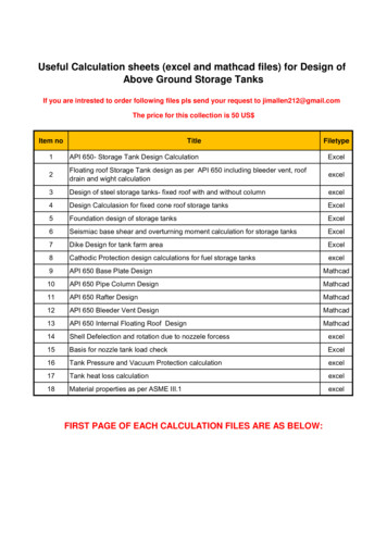
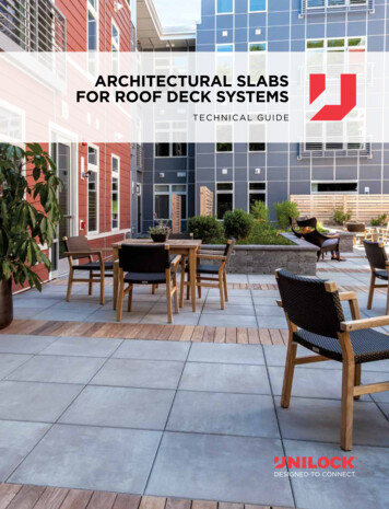
Step 5: The velocity pressure is then determined for z h 38 ft, the mean roof height used for the gable roof.qh 0.00256KzKztKdV2 0.00256(1.03)(1.0)(0.85)(95)2 20.3 psf ASCE 7 eq. 26.10-14.1.2.2 Roof Structure Components and Cladding ZonesThe development of the wind load methods for the MWFRS and C&C diverge at Step 6 of the wind pressuredetermination. The pressure Zones for the external pressure coefficients (GCp and GCpf) are different for C&Ccompared to the MWFRS.Step 6: The external pressure coefficient GCp for the steel roof deck for this example is developed fromSection 30.3 Low-Rise Buildings. This structure is enclosed with a gable end roof therefore the externalpressure coefficients are derived from ASCE 7 Figure 30.3-2A. GCp varies depending on the Zone of the roofwith lower outward pressures in the field and progressively higher pressures at the edges and corners of theroof. GCp also varies with the effective wind area to the component. The width, a, of the edge and cornerzones is based on the height of the building and the least width of the building.Figure 4.3 Components and Cladding ZonesReference ASCE Figure 30.3-2AZone Dimensions:0.6h 22.8 ft, therefore use 23 ft width for Zone 1 & 20.6h 22.8 ft, therefore use 23 ft length for Zone 30.2h 7.6 ft, therefore use 8 ft width for Zone 312ASCE 7 Figure 30.3-2A
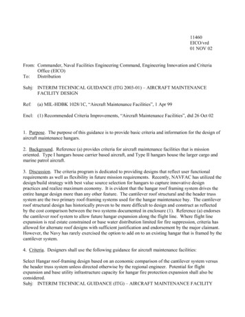
4.1.2.3 Steel Roof Deck Components and Cladding Wind PressureStep 6 (continued): The next part of Step 6 is to determine the effective wind area for the steel deck. This areais required to look up the value of GCp in the diagrams in ASCE 7 Figure 30.3-2A.The Effective Wind Area is defined in ASCE 7 Section 26.2 as follows.EFFECTIVE WIND AREA, A: The area used to determine the external pressure coefficient,(GCp) and (GCrn). For C&C elements, the effective wind area in Figures 30.3-1 through 30.37, 30.4-1, 30.5-1, and 30.7-1 through 30.7-3 is the span length multiplied by an effective widththat need not be less than one-third the span length. For rooftop solar arrays, the effective windarea in Fig. 29.4-7 is equal to the tributary area for the structural element being considered,except that the width of the effective wind area need not be less than one-third its length. Forcladding fasteners, the effective wind area shall not be greater than the area that is tributary toan individual fastener.In this example 1½ in deep PLB-36 steel roof deck with a 36 in coverage width will be supported by open websteel joists at 8 ft on center. The 1½ in deep deck is the most efficient profile for the 8 ft joist spacing and the36 in width develops higher diaphragm shears for a given attachment pattern compared to narrower 3 in deeproof deck.To determine the pressure coefficients for the wind load on the steel deck, the effective wind area for the steelroof deck is determined.L 8 ft, steel deck span between joistsw 3 ft, steel deck sheet widthw L/3 8 ft/3 2.67 ft, therefore use 3 ftEffective Wind Area of steel deck:Ae L(w) 8 ft(3 ft) 24 sfFigure 4.4 Effective Wind Area of DeckThe effective wind area for the steel deck is used to determine the external pressure coefficients (GCp andGCpf) from the chart in ASCE 7 Figure 30.3-2A. These can be read directly from the chart or can be calculatedusing the underlying equations that developed the chart which are presented in the commentary. An importantconsideration for this project is the effect of parapets. For low slope roofs with parapets there is some relief forthe high wind uplift pressures in the corner Zone 3. Note 5 in ASCE 7 Figure 30.3-2A provides the basis forthis reduction in wind pressure due to parapets.13
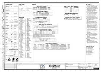
ASCE 7 Figure 30.3-2A Note 5:If a parapet equal to or higher than 3 ft is provided around the perimeter of the roof with θ 7 , thenegative values of (GCp) in Zone 3 shall be equal to those for Zone 2, and positive values of (GCp) inZone 2 and 3 shall be set equal to those for wall Zones 4 and 5 respectively, in Figure 30.3-1The top of wall in this example is 37 ft high around the entire structure. On lines A and G the roof elevationis 32 ft creating a 5 ft high parapet. At Lines 1 and 10 the roof elevation slopes from 36 ft at the ridge to 32 ftat the corner. The parapet at on lines 1 and 10 is 3 ft or greater in height until the roof height exceeds 34 ft.Based on the geometry this transition occurs 75 ft from the corner as shown in Figure 4.5. The corner Zone3 is 23 ft long which falls completely within the length of the parapet exceeding 3 ft high, therefore the relief touse the lower Zone 2 pressure in Zone 3 per Note 5 is appropriate.Figure 4.5: Parapet Heig
benefit from a steel deck and joist roof structure. This steel roof deck and joist design example offers guidance for the design professional based on current best practices in order to provide the best possible safe and economical steel roof deck and open web