Transcription
LUCAthermostatic bar mixer shower86003100Installation andoperating instructionsInstallersplease note these instructions are to be left with the user2180940CApril 2010
Thermostatic bar mixer showerContentsPageMAIN COMPONENTS. 1INTRODUCTION.2 - 3TYPICAL DOMESTIC INSTALLATIONS.4 - 6INSTALLATION.7 - 9Preparing the mixer valve. 7Siting of the shower. 7Supply pipework. 7Variable fittings. 8Making good. 9Fitting the mixer. 9FITTING THE MIXER CONTROLS. 10Leak testing the mixer. 10COMMISSIONING. 11Flow regulation. 11To fit the flow regulator. 11TEMPERATURE ADJUSTMENT RANGE. 12Recommended outlet temperatures - TMV2. 12Adjusting the maximum temperature setting. 12Operating the shower. 13Dimensions. 14Spare parts .15 - 16APPROVALS. 17TMV2 REQUIREMENTS (12 MONTHLY VERIFICATION). 17FLOW CHART. 17MAINTENANCE. 18Fault Finding.19 - 20Guarantee, service policy, etc.rear coverTo check the product suitability for commercial and multiple installations, please contact Triton’sspecification advisory service before installation.Telephone: 0844 980 0730Facsimile: 0844 980 0744E mail: technical@tritonshowers.co.uk
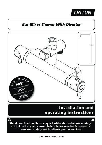
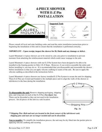
Thermostatic bar mixer showerMain componentsFig.1CCABA. Thermostatic bar mixer valveB. Dogleg connector X2C. Cover trim X2All dimensions listed in this fitting book regarding the product and installation are approximate.*All kits are for illustration purposes only and are not supplied unless otherwise stated.
Thermostatic bar mixer showerINTRODUCTIONWater temperature requirementsThis book contains all the necessary fitting andoperating instructions for your mixer shower.Please read them carefully and read throughthe whole of this book before beginning yourinstallation.Recommended maximum: 65 CMinimum hot water temperature: 55 CMaximum cold water temperature: 25 CNOTE: Valves operating outside these conditionscannot be guaranteed by the Scheme to operateas Type 2 valves.The shower installation must be carried out bya suitably competent person and in sequence ofthis instruction book.A stored water temperature of 60 C isconsidered sufficient to meet all normalrequirements and will minimise the effects ofscale in hard water areas.Care taken during the installation will give a longand trouble free life from your mixer shower.SITE REQUIREMENTSWater temperature adjustment andthermal safetyThe installation must be in accordance withwater supply (water fittings) regulation 1999and/or local Bylaws.The mixed water temperature can be adjustedfrom cold through to a top limit which mustbe preset during installation with full anti-scaldprotection throughout the range (35 C to 40 C)providing the hot water temperature at the inletremains 10 C above the outlet temperature.Water pressure requirementsRunning water pressure:Low presure*- 0.1 bar min.Should there be a loss of flow to either incomingsupply then- water from the shower will stop orbe reduced until both supplies are restored.1.0 bar max.High pressure- 0.5 bar min.5.0 bar max.SAFETY WARNINGSMaximum static water pressure:Low & High pressure- 10 bara. DO NOT choose a position where the showercould become frozen.*This mixer shower is designed for high pressuresystems found in the UK, but can be installedwith low pressure gravity water systems withreduced flow rates.b. DO NOT connect this mixer shower to anyform of tap or fitting not recommended bythe manufacturer.For effective operation of the internal seals, themaximum static pressure must not be exceeded.c.Pressure reducing valveDO NOT allow the inlet pressure or flowrates to operate outside the guidelines laidout in ‘site requirements’.d. DO NOT connect the mixer shower to agravity hot supply and a mains cold supply(or vice versa).On sites where the running pressure is above 5bar, the use of a suitably sized pressure reducingvalve fitted in the cold mains supply pipe workcan provide nominally equal pressures at themixer shower.Water minimum flow rateFor best performance within the specified runningpressure range a minimum flow of 8 litres perminute should be available to both inlets.
Thermostatic bar mixer showerPLUMBING REQUIREMENTSHard water areasDO NOT use jointing compounds on any pipefittings for the installation,a. If it is intended to operate the showerin areas of hard water (above 200-ppmtemporary hardness), a scale inhibitor mayhave to be fitted. For advice on the scaleinhibitor, please contact Customer Service.DO NOT solder fittings near the mixer unitas heat can transfer along the pipework anddamage the mixer valve.b. For best performance the showerhead MUST beregularly cleaned to remove scale and debris.DO NOT subject the unit to a water temperatureabove 80 C during installation, use, maintenanceor disinfection.WATER SYSTEM REQUIREMENTSIMPORTANT: This mixer shower is suitable for:The layout and sizing of pipework MUSTbe such that nominally equal inlet supplypressures are achieved and the effects ofother draw-offs are minimised.The pipe-work should be installed suchthat other taps and appliances beingoperated elsewhere on the premises do notsignificantly affect the flow Gravity water systems Pumped gravity systems. Fully modulating type combination boilers Multi-point hot water heaters. Thermal storage, Unvented systems When connecting pipe-work avoid usingtight 90 elbows; swept or formed bends willgive the best performance.When installing this mixer with a Combination ormulti-point boiler, it may be necessary to installflow regulation. The hot water pipe entry MUST be made tothe left-hand side inlet, marked HOT, ‘H’ orwith a red/orange label. Suitable isolating valves (complying withWater Regulations and Bylaws) MUST befitted on the hot and cold water suppliesto the shower as an independent meansof isolating the water supplies shouldmaintenance or servicing be necessary.Check that the appliance is capable of deliveringhot water at a minimum switch-on flow rateof 3 litres per minute. At flow rates between 3and 8 litres per minute, the appliance MUST becapable of raising the water temperature to 52 C(minimum). Water temperature at the inlet of the mixer valveMUST remain relatively constant when flow rateadjustments are made (refer to the applianceoperating manual to confirm compatibility withthis mixer shower).It is preferable to flush the pipe-work to clearthe system of debris and check for leaksbefore connecting to the mixer.Where thermal store systems and instantaneousgas water heaters are used, if excessive drawoff take place the appliance may not be able tomaintain an adequate output temperature.This could result in the shower temperaturebecoming noticeably cooler.The mixer inlets contain removable filtersthat may become blocked if debris is notflushed through before fitting.(Commercial applications) Flow regulators can be fitted with high-pressurewater systems to reduce flow rate and assisteconomy.It is recommended that for all commercialapplications, easily accessible, in-line filtersare used to aid maintenance.The hot supply temperature MUST remain aminimum of 10 C hotter than the required blendtemperature for optimum performance.
Thermostatic bar mixer showerTYPICAL DOMESTIC INSTALLATIONS*(diagrammatic view – not to scale)*Fig.2Domestic gravity fed systems (fig.2)The shower control MUST be fed from a coldwater cistern and hot water cylinder providingnominally equal pressures. There MUST bea minimum of one metre head of water. Theminimum head distance is measured from thebase of the cold water cistern to top of theshowerhead.Stop valveCold supplyCold watercisternMinimum headIf valves are gravity fed then supply pressureshould be verified to ensure conditions of use areappropriate for the valve.GatevalveHot supplyColdwatermainssupplyServicevalvesHot watercylinderPumped gravity fed systems (fig.3)ServicevalvesThe shower control MUST be fed from a coldwater cistern and hot water cylinder providingnominally equal pressures.MixerDrainvalveOtherdraw-offsDraw-off must point downto avoid airlock issuesThe mixer unit may be used with a gravity fedsystem with a pump to boost pressures as shown;please refer to the pump installation guide toestablish the minimum head requirements forautomatic operation of the pumpAlternative supply(must be belowvent pipe tee)*(diagrammatic view – not to scale)*Fig.3Stop valveCold watercisternCold supplyMinimum headAlternative supply(must be belowvent pipe tee)GatevalveColdwatermainssupplyHotsupplyMixerHot ervicevalvePumpIsolating switch orpull cord switch(both fused at 3A)Ring mainDraw-off must pointdown to avoid airlockissues
Thermostatic bar mixer showerInstantaneous gas-heated systems,e.g. combination boilers (fig.4)*(diagrammatic view – not to scale)*Fig.4The shower control must be installed with amulti-point gas water heater or combinationboiler of a fully modulating design (i.e.to maintain relatively stable hot watertemperatures).MixerA drop tight pressure reducing valve mustbe fitted if the supply pressures exceed 5 barrunning.CombinationboilerServicevalvesAn expansion vessel MAY be fitted, and regularlymaintained, to prevent the shower mixerbeing damaged by excess pressures. This mayalready be installed within the boiler (check withmanufacturer) and is in addition to the normallylarger central heating expansion vessel.Hot waterCH flowExpansionvesselColdmainssupplyUnvented mains pressure systems (fig.5)StoptapThe shower control can be installed with anunvented, stored hot water cylinder.For systems with no cold water take off after theappliance reducing valve, it will be necessary tofit an additional drop tight pressure-reducingvalve when the mains pressure is over 5 bar. Thedrop tight pressure reducing valve MUST beset at the same value as the unvented packagepressure reducing valve.Pressurereducing valve*(diagrammatic view – not to scale)*Fig.5Note: An additional expansion vessel may berequired if a second pressure-reducing valve isinstalled. This does not apply to packages with acold take off after the pressure-reducing valve tothe cylinder.CH returnMixerSafety devicesnot shownServicevalvesUnventedhot waterstorage unitExpansionvesselPressurereducing valvesBalanced cold mains supplyStop tap Cold mains supply
Thermostatic bar mixer showerMains pressurised thermal store systems (fig.6)*(diagrammatic view – not to scale)*Fig.6Packages of this type, fitted with a temperingvalve (blender valve) can be used. A drop tightpressure reducing valve must be fitted if thesupply pressures exceed 5 bar running.An expansion vessel must be fitted, andregularly maintained, to ensure, the unit, isnot damaged by excess pressures. This mayalready be installed externally or internally withinthe thermal store (check with thermal storemanufacturer).MixerServicevalvesHot BlendervalvewaterExpansionvesselPressurereducing valveStop tapReturnFlowBoilerCold mains supply
Thermostatic bar mixer showerINSTALLATION*Fig.7*(diagrammatic view – not to scale)PREPARING THE MIXER VALVECheck the contents to make sure all items arepresent.Before starting, make sure all of the openings onthe valve are carefully covered to stop ingressof any debris, etc. while routing the supplypipework.The shower valve is suitable for exposedinstallation onto: Solid wall Stud partition wall Dry lined wall Laminate cubicle or panel.Showerhead canbe mountedeither side of themixerHeight ofshowerheadto suit user’srequirementsSITING OF THE SHOWER & ACCESSORIESRefer to (fig.7) for correct siting of the shower.The mixer valve should be positioned, asdetailed, with all controls within comfortablereach of the user.The accessories (showerhead, riser rail and/orfixed showerhead) can be positioned above or toeither side of the shower.The valve must be installed in a position thatallows for easy access for future maintenance andcommissioning.*IMPORTANT!BEFORE FIXING the supply pipework withinthe wall, refer to the ‘SUPPLY PIPE WORK’and ‘VARIABLE FITTINGS’ sections.See figures 8, 9 and 10 to ensurethe MINIMUM of 7mm of thread isavailable once the cover trims are fitted.*SUPPLY PIPE WORK Complete the pipework to the shower areahaving decided on the position of the showerand direction of pipe entry (for examplerising, falling or rear entry)The hot and cold water pipes should be securelyattached within the wall or panel to support thevalve and prevent movement after installation.THIS IS REQUIRED TO ALLOW THECORRECT FITTING OF THE MIXER VALVE.Pipe fitting depth should be checked inconjunction with the information given in(fig.8) - a MINIMUM of 7mm of threadMUST be available once the Variable Fitting issecured into the wall end fitting and the covertrim has been fitted. This is to allow the mixer tobe fitted correctly. Inlet pipe centres should beapproximately 150mm apart.
Thermostatic bar mixer shower*VARIABLE FITTINGSFig.8The supply pipes can be routed from the side,rising, rear or falling and must end in suitablefittings (fig.8) to accept the variable connectors.The variable connectors can be used to connectto ½” BSP female elbow fittings in solid wallinstallations. The inlet centres on the variableconnectors have a degree of adjustment to allowfor misalignment of pipe work.Appropriateend fittingThe hot and cold supply pipes MUST beanchored rigidly to support the valve and stopany movement after installation.Once the trimis fitted, thereMUST be aminimum of7mm of threadto allow themixer to befitted correctly.Fig.97mmSeal aroundthe variableconnectors
Thermostatic bar mixer showerMAKING GOODFig.10 Make good the wall and complete the tiling.Note: It is advised to use a suitable sealer aroundthe variable connector where it enters the wall tostop water ingress (fig.9). Screw the supplied cover trims onto thefittings until tight to the wall (fig.10).FITTING THE MIXERIMPORTANT: Make sure that all supply pipeworkhas been flushed through before fitting the mixer. Offer the shower valve up to the fittings. Check that the sealing washers are in place. Screw the unions onto the fittings. Fit the mixer controls (fig.11 & 12) andcarry out the commissioning procedure.
Thermostatic bar mixer showerFig.11MaximumtemperaturestopFitting the mixer controlsThe mixer controls will need to be fitted beforecommissioning can be carried out.Temperature control Fit the maximum temperature stop. Theorientation is shown in (fig.11).Lower verticalflat of the maxtemp stop inthe 6 o’clockposition To fit the temperature control (right handside), position the temperature overridebutton in the 12 o’clock position. Once inplace, fit the retaining screw (fig.11).Flow control - (fig.12) To fit the flow control (left hand side), theflow control cartridge needs to be turned fullyclockwise until it stops.Note: The flow control graphic (styles of this mayvary) should be positioned so that the front edgeof it is at the 12 o’clock position. The remainderof the graphic should run towards you.Temperatureoverride buttonin the 12 o’clockposition If fitted correctly, the graphic and flow controlshould now be sitting in the designed ‘OFF’position. Once in place, fit the retaining screw. Do not fit the end trims until thecommissioning procedure has been carriedout and the temperature range checked.Fig.12LEAK TESTING THE MIXERFront ofgraphic in the12 o’clockpositionIMPORTANT: Flush out the pipework inaccordance with Water Regulations and Bylaws. Fit the hose to the outlet (without theshowerhead fitted) and direct it towards thewaste outlet. Open the water isolating valves to theshower and check for leaks. If any leaks are found, rectify them beforecarrying out the commissioning procedure.Turn the flowcontrol fullyclockwiseFlow control graphic(style may vary)10
Thermostatic bar mixer showerCOMMISSIONINGFig.13 Start the water flow by rotating the flowcontrol (left hand side) anticlockwise.Mixer outlet Make sure that the hot and cold watersupplies are fully open and at (or near to)their design temperature and pressures, andare within the requirements as stated onPage 2 & 14. Make sure the temperature control (righthand side) is at the maximum temperaturesetting WITHOUT operating the maximumtemperature override button.Flow regulatorFlow regulator Allow the shower to run at this maximumtemperature setting until the watertemperature has stabilised.Top Rotate the temperature control until yourdesired ‘maximum temperature stop’showering temperature is reached.Water flowAngled topsectionNote: the flow regulator must be fitted with theangled top facing the outlet flow of water.Note: If your desired temperature is above themaximum temperature stop limit, please see‘ADJUSTING THE MAXIMUM TEMPERATURESTOP SETTING’ on Page 12. A final temperature check SHOULD be madeon-site to guarantee user safety, and that themixer falls within recommended ‘maximummixed water outlet temperatures’ - as statedon Page 12.FLOW REGULATIONA flow regulator is supplied for use with highpressure water systems. It may be fitted withany of the systems listed to reduce flow rate andassist economy.TO FIT THE FLOW REGULATORFit the flow regulator into the outlet fitting asshown in (fig.13).11
Thermostatic bar mixer showerTemperatureoverridebuttonFig.14TEMPERATURE ADJUSTMENT RANGEThe mixer has a temperature stop to preventaccidental rotation to higher temperatures. Thisis adjustable to provide a maximum temperatureof 35 C – 45 C.The mixed water temperature can be adjustedfrom cold through to a top limit (which canbe pre-set during installation – factory setat approximately 38 C) with full anti-scaldprotection throughout the range - SEE PAGE 17.Recommended outlet temperaturesFig.15The BuildCert TMV scheme recommends thefollowing set maximum mixed water outlettemperatures for use in all premises:44 C - for bath fill but see notes below.Temperaturespindle41 C - for showers.41 C - for washbasins.38 C - for bidets.The mixed water temperatures must neverexceed 46 C at terminal fitting.The British Burns Association recommends 37 to37.5 C as a comfortable bathing temperaturefor children. In premises covered by the CareStandards Act 2000, the maximum mixed wateroutlet temperature is 43 C.ADJUSTING THE MAXIMUMTEMPERATURE STOP SETTING Remove the end trim from the temperaturecontrol to allow access to the retainingscrew. Undo the retaining screw and pull thetemperature control off (fig.14). The maximum temperature stop does notneed to be removed. Turn the flow control to full flow. With asteady flow running, adjust the temperaturespindle until the temperature is about 38 C(fig.15). When the showering temperature issatisfactory turn off the shower. Refit thetemperature control, making sure the overridebutton aligns to 12 o'clock. Secure the temperature control in place withthe screw and fit the trim.12
Thermostatic bar mixer showerOperating the showerFig.16 To start the shower, rotate the flow control(left-hand side) anti-clockwise. For maximumflow, rotate the flow control anti-clockwiseuntil it stops.To stop the water flow, rotate the flowcontrol clockwise until the water stopsflowing (fig.16). To adjust the water temperature, rotatethe temperature control (right-hand side),clockwise for a cooler shower, oranti-clockwise for a hotter shower (fig.17). To overcome the maximum temperature stop,depress the temperature override button(fig.17) on the temperature control androtate clockwise past the '38 C' position.Flow controlCAUTION: Exposed metal and chromed surfacesmay become hot during rol13
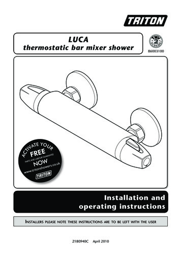
Thermostatic bar mixer showerDimensions50mm40mmAll dimensions listed in this fitting book regarding the product and installation are approximate.14180mm150mm1/2” BSP280mm3/4” BSP
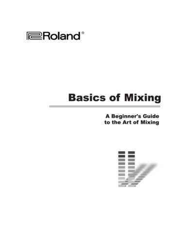
Thermostatic bar mixer showerSpare parts41562136Ref. DescriptionPart No.1. Flow control & temperatureknobs860031602. Flow control cartridge833137303. Thermostatic cartridge833137204. Trim pack860011505. Non return valves (NRV)833084706. Trim pack (knobs)83314110-Flow regulator2201128015
Thermostatic bar mixer shower*Spare parts - bar mixer fittingsABRef. DescriptionPart No.A. Bar bracketUNBMXBKTB. Bar bracket (exposed)UNBMXFIXEXC. Bar bracket (push-fit)UNBMXFIXBTD. Straight connector86001120E. Dogleg connector86001110The bar mixer fittings can be purchased fromCustomer Spares. Please check that they aresuitable for your installation requirementsbefore ordering.CDE* Not supplied unless otherwise statedT0036016
Thermostatic bar mixer showerAPPROVALSThis mixer valve is approved to the requirements of:* BS EN 1111*On pressures above 0.5 bar.* WRASDesignation: HP-S (high pressure shower only)TMV2 REQUIREMENTS (12 MONTHLY VERIFICATION)It is a requirement that all TMV2 approved valves shall be verified against the original settemperature results once a year.On installation and on a yearly basis please perform the following checks:1. Cold water supply isolation testIsolating the cold water supply to the TMV, wait for five seconds if water is still flowing check thatthe temperature is below 46C.If there is no significant change to the set outlet temperature ( 2 C or less change from theoriginal settings) and the fail-safe shut off is functioning, then the valve is working correctly andno further service work is required.If there is a residual flow during the commissioning or the annual check this is acceptableproviding the temperature of the water seeping from the valve is no more than 2C above thedesignated maximum mixed water outlet temperature setting of the valve.Note:Temperature readings should be taken at the normal flow rate after allowing for the system to stabilise.The sensing part of the thermometer probe must be fully submerged in the water that is to be tested.FLOW CHART17
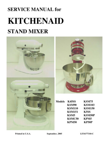
Thermostatic bar mixer showerMAINTENANCECleaningThe following maintenance procedure mustbe carried out for commercial and health carepremises, but is not necessarily required fordomestic installations.It is recommended that all products are cleanedusing warm, soapy water.Maintenance of the unit is required to givecontinued performance after installation and thatit continues to provide scald prevention.Do not use abrasive or aggressive chemicalcleaning products as this may affect the productsurface finish and invalidate your guarantee.Cleaning the filters (fig.A)Note: a thermostatic mixing valve in need ofmaintenance can be undetectable in normal useand only becomes apparent when a disruptionoccurs in the hot or cold watersupply temperatures or pressures.It is advised that this should be carried out by aqualified person.It is a requirement that all TMV2 approvedvalves shall be verified against the original settemperature results once every 12 months. Remove the filter housing and disassemble.a) Initially check the filters for debris once everythree months and clean if necessary. Turn off the water supplies before starting. To gain access to the filters remove the unitfrom the inlet fittings. Wash the filters thoroughly under runningwater, use a suitable brush to remove all debris. Reassemble and fit in reverse order.b) Perform a thermal shut off testevery three months, and check themaximum temperature setting. See the‘Commissioning’ section for the details ofthis test and readjustment of the maximumtemperature setting if required.Note: the filterhousing is Lefthand thread.non-return valve‘O’ ringc) If the maximum water temperature variesby more than 2 C from the commissionedsetting then carry out the following checksFilter Check the isolating valves are fully open. Check the internal surface for scaling.If the body requires descaling then it should beremoved from the pipework to carry this workout (all rubber parts MUST be removed beforedescaling). Check the function of the non-return valves.The non-return valves (NRVs) prevent cross-flowbetween hot and cold supplies under unequalpressure conditions. They are designed for longlife with no maintenance.Filter housingFig.ADisinfectionWhere chlorine is used for the disinfectionof water systems all relevant guidelines andapproved codes of practice must be strictlyfollowed. Failure to comply with the relevantguidelines and approved codes of practice mayinvalidate your guarantee.Note: the (NRV’s) will only operate in one direction- water should be able to flow into the unit from theinlets, but NOT back out through the inlets.WARNING!Do not use ‘powerful’ abrasive orsolvent cleaning fluids when cleaning theshower as they may damage the fittings.If these checks do not highlight the reasonfor the temperature variation, then internalcomponents will require replacement - please seethe spare parts list.18
Thermostatic bar mixer showerFAULT FINDINGThe following can be carried out by a competent personProblem/SymptomCauseAction/Cure1 Water too hot.1.1 Temperaturecontrol incorrectlycommissioned.1.1.1 Refer to commissioning section.1.2 Not enough coldwater flowing throughshower.1.2.1 Reposition temperature control knob1.3 Increase in theambient cold watertemperature.1.3.1 Reposition temperature control knob.1.4 Cold water supplyblocked.1.4.1 Turn off the shower and consult acompetent plumber or contactCustomer Service.1.5 High volume of coldwater drawn offelsewhere.1.5.1 Reduce the simultaneous demand fromthe supply.2.1 Temperature controlincorrectlycommissioned.2.1.1 Refer to 'commissioning' section.2.2 Not enough hot waterflowing throughshower.2.2.1 Reposition temperature control knob2.3 Decrease in theambient cold watertemperature.2.3.1 Reposition temperature control knob2.4 Insufficient hot watersupplies from theheating system.2.4.1 Make sure heating appliance is set tomaximum or has sufficient stored hot water.2.4.2 Make sure heating appliance is igniting bytrying a hot water tap elsewhere.2.5 Hot water supplyblocked or restricted.2.5.1 Turn off shower and consult a competentplumber or contact Customer Service.2.6 Flow regulator notfitted (HP systemsonly).2.6.1 Fit the supplied flow regulator (Page 11).2 Water too cold.3 High water flow 3.1 Flow regulators notand/or poorfitted.performance on amains fed system.3.1.1 Fit flow regulator (Page 11).19
Thermostatic bar mixer showerFAULT FINDINGProblem/SymptomCauseAction/Cure4 Water doesnot flow orshower patterncollapses whenanother outletis turned on.4.1 Water supplies cut off.4.1.1 Check water elsewhere in house and ifnecessary contact local water company.4.2 Shower unit blocked.4.2.1 Inspect the inlet filters. Clean if necessary.4.3 Blockage in pipework.4.3.1 Turn off the shower and consult a suitablycompetent plumber.4.4 Showerhead blocked.4.4.1 Clean showerhead.4.5 System not capableof supplying multipleoutlets at the sametime.4.5.1 Reduce the simultaneous demand.4.5.2 Make sure stop/service valves are fullyopen.4.5.3 Check if sufficient water pressure.The following is recommended for a professional qualified installer only5 Water too cold.5.1 Running pressure inexcess of maximumrecommended.5.1.1 Fit a pressure reducing valve.6 Shower controlsnoisy while inuse.6.1 Running pressure inexcess of maximumrecommended.6.1.1 Fit a pressure reducing valve.7 Shower will notshut off.7.1 Flow control cartridgeworn.7.1.1 Renew flow control cartridge.20
Thermostatic bar mixer shower21
UK SERVICE POLICYTRITOn STandaRd GUaRanTEEIn the event of a product fault or complaint occurring, thefollowing procedure should be followed:1. Telephone Customer Service on 0844 980 0750 having available,your details including post code, the model number and powerrating of the product, together with the date of purchase.2. Based on information given over the telephone, a Triton CustomerService Advisor will attempt to diagnose the fault and confirmwhether a site visit from a qualified service engineer is required.3. All products attended to by a Triton service engineer mustbe installed in full accordance with the Triton installationguide applicable to the product. (Every product pack containsan installation guide, however, they can also be bought via ourCustomer Service Spares Department).4. Our engineer will require local parking and if a permit is requiredthis must be available to the engineer on arrival at the call.5. It is essential that you or an appointed representative (who mustbe over 18 years of age) is
Low presure* - 0.1 bar min. 1.0 bar max. High pressure - 0.5 bar min. 5.0 bar max. Maximum static water pressure: Low & High pressure - a.10 bar *This mixer shower is designed for high pressure systems found in the UK, but can be installed with low pressure gravity water systems with reduced flow rates.