Transcription
Bar Mixer Shower With DiverterInstallation andoperating instructionsThe showerhead and hose supplied with this product are a safetycritical part of your shower. Failure to use genuine Triton partsmay cause injury and invalidate your guarantee.2181414B - March 2018
Bar mixer showerCONTENTSPageMAIN COMPONENTS.1DIMENSIONS.2 - 3INTRODUCTION.4 - 5TYPICAL DOMESTIC INSTALLATIONS.6 - 7SITING OF THE SHOWER.8PREPARING THE MIXER VALVE.8INSTALLING THE BAR MIXER BRACKET.8FITTING THE BAR MIXER.8 - 11OPERATING THE SHOWER.12LEAK TESTING.13COMMISSIONING.13TEMPERATURE ADJUSTMENT.14ADJUSTING THE MAXIMUM TEMPERATURE SETTING.14SPARE PARTS.15 - 16MAINTENANCE.17FAULT FINDING.18 - 19GUARANTEE, SERVICE POLICY, ETC. rear coverInstallersplease note these instructions are to be left with the userTo check the product suitability for commercial and multiple installations, please contact Triton’sspecification advisory service before installation. Please see back of book for contact information.
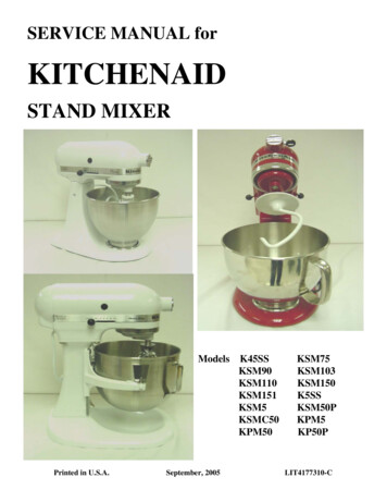
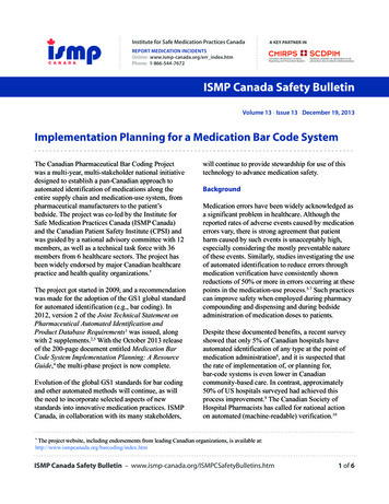
Bar mixer showerMAIN COMPONENTSEFDBACA. Thermostatic mixer valveB. Riser pipeC. Push Fit BracketD. Wall BracketE. Fixed head pipeF.SliderG. Hose (not shown)H. Handset (not shown)I.Fixed showerhead (not shown)1
Bar mixer showerDIMENSIONS15028313111196452
Bar mixer shower112740073055-75mmIMPORTANTAll dimensions listed in this fitting book regarding the productand installation are approximate.Consideration must be given for the adequate ceiling space.3
Bar mixer showerINTRODUCTIONPressure reducing valveThis book contains all the necessary fitting andoperating instructions for your mixer shower.Please read them carefully and read throughthe whole of this book before beginning yourinstallation.On sites where the running pressure is above 5bar, the use of a suitably sized pressure reducingvalve fitted in the cold mains supply pipe workcan provide nominally equal pressures at themixer shower.The shower installation must be carried out bya suitably competent person and in sequence ofthis instruction book.Water minimum flow rateFor best performance within the specified runningpressure range a minimum flow of 8 litres perminute should be available to both inlets.Care taken during the installation will give a longand trouble free life from your mixer shower.SITE REQUIREMENTSWater temperature adjustment andthermal safetyThe installation must be in accordance withwater supply (water fittings) regulation 1999and/or local Bylaws.Maximum staticpressure (Bar)The mixed water temperature can be adjustedfrom cold through to a top limit which mustbe preset during installation with full anti-scaldprotection throughout the range (35 C to 40 C)providing the hot water temperature at the inletremains 10 C above the outlet temperature.10Flow pressure, Hot&Cold (Bar)0.5 to 5Hot supplytemperature ( C)55 to 65Cold supplytemperature ( C)Equal to or less than 25Should there be a loss of flow to either incomingsupply then water from the shower will stop orbe reduced until both supplies are restored.SAFETY WARNINGSDO NOT allow the inlet pressure or flow ratesto operate outside the guidelines laid out in ‘siterequirements’.This mixer shower is designed for high pressuresystems found in the UK, but can be installedwith low pressure gravity water systems withreduced flow rates.DO NOT connect the mixer shower to a gravityhot supply and a mains cold supply or vice versa.For effective operation of the internal seals, themaximum static pressure must not be exceeded.APPROVALSThis mixer valve has the following approvalsA stored water temperature of 60 C isconsidered sufficient to meet all normalrequirements and will minimise the effects ofscale in hard water areas. 4WRAS
Bar mixer showerPLUMBING REQUIREMENTSHard water areasDO NOT choose a position where the mixershower could become frozen.DO NOT connect to any form of tap or fittingnot recommended by the manufacturer.DO NOT use jointing compounds on any pipefittings for the installation,a. If it is intended to operate the showerin areas of hard water (above 200-ppmtemporary hardness), a scale inhibitor mayhave to be fitted. For advice on the scaleinhibitor, please contact Customer Service.b. For best performance the showerhead MUST beregularly cleaned to remove scale and debris.DO NOT solder fittings near the mixer unitas heat can transfer along the pipework anddamage the mixer valve.WATER SYSTEM REQUIREMENTSDO NOT subject the unit to a water temperatureabove 80 C during installation, use, maintenanceor disinfection.This mixer shower is suitable for:IMPORTANT: The layout and sizing of pipework MUSTbe such that nominally equal inlet supplypressures are achieved and the effects ofother draw-offs are minimised. The pipework should be installed suchthat other taps and appliances beingoperated elsewhere on the premises do notsignificantly affect the flow When connecting pipework avoid using tight90 elbows; swept or formed bends will givethe best performance. The hot water pipe entry MUST be made tothe left-hand side inlet, marked HOT, ‘H’ orwith a red/orange label. Suitable isolating valves (complying withWater Regulations and Bylaws) MUST befitted on the hot and cold water suppliesto the shower as an independent meansof isolating the water supplies shouldmaintenance or servicing be necessaryposition as close as is practicable to the watersupply inlets of the mixer shower. Gravity water systems Pumped gravity systems Fully modulating type combination boilers Multi-point hot water heaters Thermal storage Unvented systemsWhen installing this mixer with a combination ormulti-point boiler, it may be necessary to installflow regulation.Check that the appliance is capable of deliveringhot water at a minimum switch-on flow rateof 3 litres per minute. At flow rates between 3and 8 litres per minute, the appliance MUST becapable of raising the water temperature to 52 C(minimum).Water temperature at the inlet of the mixer valveMUST remain relatively constant when flow rateadjustments are made (refer to the applianceoperating manual to confirm compatibility withthis mixer shower).Where thermal store systems and instantaneousgas water heaters are used, if excessive draw-offtakes place, the appliance may not be able tomaintain an adequate output temperature.This could result in the shower temperaturebecoming noticeably cooler.Flush pipework to clear the system of debrisand check for leaks before connecting to themixer.Flow regulators can be fitted with high-pressurewater systems to reduce flow rate and assisteconomy.Commercial applications For commercial applications in-line filters arerecommended.The hot supply temperature MUST remain aminimum of 10 C hotter than the required blendtemperature for optimum performance.5
Bar mixer showerTYPICAL DOMESTIC INSTALLATIONS*(diagrammatic view – not to scale)*Fig.1Pumped gravity fed systems (fig.1)The shower control MUST be fed from a coldwater cistern and hot water cylinder providingnominally equal pressures.Stop valveCold watercisternCold supplyAlternative supply(must be belowvent pipe tee)GatevalveThe mixer unit may be used with a gravity fedsystem with a pump to boost pressures as shown;please refer to the pump installation guide toestablish the minimum head requirements forautomatic operation of the pump.Minimum headHotsupplyColdwatermainssupplyMixerHot eIsolating switchor pull cordswitch (bothfused at 3A)Otherdraw-offsDraw-off must pointdown to avoid airlockissues*Fig.2Ring main*(diagrammatic view – not to scale)Instantaneous gas-heated systems,e.g. combination boilers (fig.2)The shower control MUST be installed with amulti-point gas water heater or combinationboiler of a fully modulating design (i.e.to maintain relatively stable hot watertemperatures).A drop tight pressure reducing valve MUSTbe fitted if the supply pressures exceed 5 barrunning.An expansion vessel MAY be fitted, and regularlymaintained, to prevent the shower mixerbeing damaged by excess pressures. This mayalready be installed within the boiler (check withmanufacturer) and is in addition to the normallylarger central heating expansion vessel.CombinationboilerMixerServicevalvesHot waterColdmainssupplyExpansionvesselCH flowCH returnPressureStoptap reducing valve6
Bar mixer showerUnvented mains pressure systems (fig.3)*(diagrammatic view – not to scale)*Fig.3The shower control can be installed with anunvented, stored hot water cylinder.For systems with no cold water take off after theappliance reducing valve, it will be necessary tofit an additional drop tight pressure-reducingvalve when the mains pressure is over 5 bar. Thedrop tight pressure reducing valve must be set atthe same value as the unvented package pressurereducing valve.MixerSafety devicesnot shownNote: An additional expansion vessel may berequired if a second pressure reducing valve isinstalled. This does not apply to packages with acold take off after the pressure reducing valve tothe cylinder.ServicevalvesUnventedhot waterstorage unitExpansionvesselPressurereducingvalvesMains pressurised thermal store systems (fig.4)Stop tap*Fig.4Packages of this type, fitted with a temperingvalve (blender valve) can be used. A drop tightpressure reducing valve MUST be fitted if thesupply pressures exceed 5 bar running.Balanced cold mains supplyCold mains supply*(diagrammatic view – not to scale)An expansion vessel MUST be fitted and regularlymaintained to ensure the unit is not damaged byexcess pressures. This may already be installedexternally or internally within the thermal store(check with thermal store esExpansionvesselPressurereducing valveStop tapCold mains supply7ReturnFlowBoiler
Bar mixer shower*Fig.5PREPARING THE MIXER VALVE*(diagrammatic view – not to scale)Check the contents to make sure all parts arepresent.Before starting the mixer installation, makesure all the openings on the valve are carefullycovered to stop ingress of any debris etc., whilerouting the supply pipework.Showerhead can bepositionedeither sideof the rail.Considerationmust be givenfor adequateceiling spaceThe shower valve is suitable for exposedinstallation onto solid wall, a stud partition wall,dry lined wall or fixing to a laminate cubicle orpanel.Height of theshowerheadto suit user’srequirement.SITING OF THE SHOWER ANDACCESSORIESRefer to fig.5 for correct siting of the shower.The mixer valve should be positioned as detailed,with all controls within comfortable reach of theuser.The handset can be positioned above or to eitherside of the shower.INSTALL BAR MIXER BRACKETSFig.6Guidance on installing the bar mixer brackets(fig.6) can be found in a separate instructionbook (supplied).Please read the instructions carefully.Read through the whole of this guide beforebeginning installation.The wall brackets installation must be carriedout by a suitably competent person and in thesequence of the instruction book.8
Bar mixer showerINSTALLATIONFig.7FITTING THE DIVERTERBefore the mixer shower can be fitted to the wallbrackets the diverter must be fitted.Carefully push the diverter onto the connector atthe top face of the valve (fig.7).Once the diverter has been fitted and facesforward fully tighten the small retaining grubscrew located at the rear of the diverter assembly(fig.8).Fig.8Fig.9FITTING THE MIXER SHOWEROffer the shower valve to the bar mixer brackets,check that the sealing washers are in place andcarefully tighten the nuts.Care must be taken not to damage the chromeplated surface (fig.9).9
Bar mixer showerFITTING THE RISER/FIXED HEAD RAIL Mark the centre hole for the wall bracket (seefig.10). Drill and plug the wall. The wall plugs aresuitable for most brick walls – use an appropriatemasonry drill, but if the wall is plasterboard or asoft building block, use suitable wall plugs andan appropriate drill bit. Secure the bracket to the wall.Fig.10Note: The elongated hole in the wall bracketallows for a small amount of adjustment.Fig.11RISER KIT ASSEMBLY Seat the upper part of the rail into the railsupport, making sure the bracket engagesthe hexagonal fitting and the ‘O’ ring is inplace (fig.11).Upper rail‘O’ ringRetainingscrewUsing a suitable screwdriver, tighten theretaining screw to secure the rail into thesupport. Screw the bottom part of the rail tothe upper section and tighten.Rail supportNote: The upper and lower riser pipework MUSTnot be cut. The product may not perform withinstated specifications if altered. Alterations mayinvalidate the warranty.bottom railFig.12FITTING THE SHOWERHEAD HOLDERWhile depressing the button on the showerheadholder (fig.12), slide the holder onto the railbelow the bracket.Lower shower armPress and holdbutton to unlockmechanismSlider/holderassembly10
Bar mixer showerRISER KIT INSTALLATIONFig.13 Slide the diverter collar and rubber seal(making sure the tapered part of the seal isat the bottom) over the base of the riserrail assembly and fit into the outlet of thediverter (fig.13). Carefully locate the rail holder into thewall bracket (fig.14). Secure in place bytightening the grub screw in the bracket. Tighten the diverter collar.Fig.14Grub screwFITTING THE HOSE AND HANDSETFig.15 Connect one end of the flexible hose to thebottom outlet connector (fig.15) on thediverter valve, making sure that the sealingwasher is in place. Screw the other end of the hose to thehandset then locate the handset into thehandset holder. Screw the fixed head to the riser/fixed headrail. Make sure the sealing washer is in placeand screw tight to seal the joint.ShowerheadWashersImportant: It is the conical end of the hosewhich grips into the holder. The showerhead willnot fit in the holder without the hose attached.11
Bar mixer showerFig.16OPERATING THE SHOWERFLOW CONTROL Fig.17To start the mixer, rotate the on/off flowcontrol (left-hand side) (fig.16).TEMPERATURE CONTROL To adjust the water temperature, rotatethe temperature control (right-hand side)clockwise for cool or anti-clockwise for hot(fig.17). To overcome the maximum temperaturestop, press the override button and turn.12
Bar mixer showerDIVERTER CONTROLFig.18The diverter fitted to this product has twoposition settings.The first position allows the user to select the‘overhead’ shower head and the second positionselects the ‘hand held’ shower head.The positions are selected by rotating the handleclockwise or anticlockwise (fig.18).LEAK TESTINGFit the hose to the outlet and direct it to waste.Open the isolating valves to the shower andcheck for leaks. Remedy any leaks found.COMMISSIONING Start the water flow by rotating the flowcontrol (left hand side). Make sure that the hot and cold watersupplies are fully open and at (or near to)their design temperature and pressures, andare within the requirements stated in the siterequirements. Make sure the temperature control (right handside) is at the maximum temperature setting. Allow the shower to run at this maximumtemperature setting until the watertemperature has stabilised. Rotate the temperature control until yourdesired showering temperature is reached.IMPORTANTThe temperature adjustment range must bechecked to guarantee user safety. Rotate the temperature control checkingthe minimum and maximum showeringtemperatatures; ADJUST THE MAXIMUMTEMPERATURE STOP SETTING if required. The following is recommended for domesticinstallations but must be carried out forcommercial installations. Perform a thermalshut off test described within the maintenancesection13
Bar mixer showerTEMPERATURE ADJUSTMENTFig.19ImportantThe mixer has a temperature stop to preventaccidental rotation to higher temperatures. Thisis adjustable to provide a maximum temperatureof 35 C – 46 C.The mixed water temperature can be adjustedfrom cold through to a top limit (which canbe pre-set during installation – factory setat approximately 38 C) with full anti-scaldprotection throughout the rangeAdjusting the maximum temperatureoverride setting Remove the temperature control byremoving the end cap and unscrewing theretaining screw (fig.19). Turn the flow control to full flow.With a steady flow running, adjust thetemperature valve spindle until thetemperature is about 38 C. When you are satisfied with the temperatureturn the flow control off. Refit thetemperature control. Secure with the screwand replace the end cap.Recommended outlet temperaturesThe BuildCert TMV scheme recommends amaximum mixed water outlet temperatures of41 C for showers.The mixed water temperatures must neverexceed 46 C.The British Burns Association recommends 37 Cto 37.5 C as a comfortable bathing temperaturefor children.WARNINGSExposed metal surfaces may become hot duringuse.14
Bar mixer showerSPARE PARTS412131Ref. DescriptionPart No.1.Control Knobs. 860052602.Flow Control Cartridge. 833166803.Thermostatic Cartridge. 833161904.Diverter cartridge. 8331669015
Bar mixer shower10911812Ref. DescriptionPart No.8.Lower shower arm. 884000399.Bracket. 2201358810. Upper shower arm. 8840004111. Slider. 2201351012. Hose. 2810030016
Bar mixer showerMAINTENANCECleaningThe following maintenance procedure isrecommended for domestic installations butmust be carried out for commercial installations.The manufacturer recommends that all productsare cleaned using warm, soapy water.Maintenance of the unit is required to givecontinued performance after installation and thatit continues to provide scald prevention.Note: A thermostatic mixing valve in need ofmaintenance can be undetectable in normaluse and only becomes apparent when adisruption occurs in the hot or cold water supplytemperatures or pressures.The frequency of routine maintenance of theinternal of the valve will depend mainly on thewater supply condition. Experience of localconditions will dictate the intervals for inspectionand in-service testing; guidance has beengiven below which can be adjusted for localrequirements.a) Initially check the filters for debris once everythree months and clean if necessary.Do not use abrasive or aggressive chemicalcleaning products as this may affect the productsurface finish and invalidate your guarantee.Cleaning the filters (fig.A)It is advised that this should be carried out by aqualified person.It is advised that a qualified person should carrythis out.Turn off the water supplies before starting.To gain access to the filters remove the unit fromthe inlet fittings.Remove the sealing washers from the inlets.Wash thoroughly under running water to remove alldebris using a suitable brush. Refit the sealing washerand reassemble the shower onto the inlet fittings.b) Perform a thermal shut off testevery three months, and check themaximum temperature setting. See the‘Commissioning’ section for the details ofthis test and readjustment of the maximumtemperature setting if required.c) If the maximum water temperature variesby more than 2 C from the commissionedsetting then carry out the following checksFilter Check the isolating valves are fully open.Fig.A Check the internal surface for scaling.If the body requires descaling then it should beremoved from the pipework to carry this work out(all rubber parts must be removed before descaling). Check the function of the non-return valvesThe non-return valves (NRVs) prevent cross-flowbetween hot and cold supplies under unequalpressure conditions. They are designed for longlife with no maintenance.O ringDisinfectionWhere chlorine is used for the disinfectionof water systems all relevant guidelines andapproved codes of practice must be strictlyfollowed. Failure to comply with the relevantguidelines and approved codes of practice mayinvalidate your guarantee.If these checks do not highlight the reasonfor the temperature variation, then internalcomponents will require replacement; please seethe spare parts list.WARNING!DO NOT use ‘powerful’ abrasive orsolvent cleaning fluids when cleaning theshower as they may damage the fittings.17
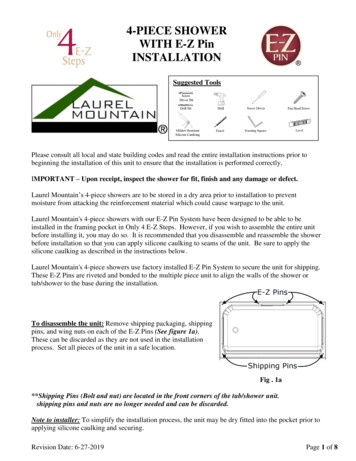
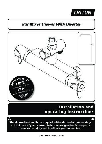
Bar mixer showerPRODUCT FLOW RATESFlow Rate (l/m)1.02.54.05.06.08.013.5 17.0 19.5 22.0Pressure (bar)0.10.20.30.40.51.02.0Conditions for testInlet temperatures comply with EN1111 requirements.Outlet temperature 38C.Flow control fully open.Open outlet - No hose or shower head connected.ImportantProduct flow rates are for guidance only.183.04.05.0
Bar mixer shower19
Bar mixer showerFAULT FINDINGThe following can be carried out by a competent personProblem/SymptomCause1 Water too hot.1.1 Temperature controlincorrectlycommissioned.1.1.1 Refer to commissioning section.1.2 Not enough coldwater flowing throughshower.1.2.1 Reposition temperature control knob1.3 Increase in theambient cold watertemperature.1.3.1 Reposition temperature control knob.1.4 Cold water supplyblocked.1.4.1 Turn off the shower and consult a competent plumber or contact Moretti CustomerService.1.5 High volume of coldwater drawn offelsewhere.1.5.1 Reduce the simultaneous demand from thesupply.2.1 Temperature controlincorrectlycommissioned.2.1.1 Refer to commissioning section.2.2 Not enough hotwater flowing throughshower.2.2.1 Reposition temperature control knob2.3 Decrease in theambient cold watertemperature.2.3.1 Reposition temperature control knob2.4 Insufficient hot watersupplies from theheating system.2.4.1 Make sure heating appliance is set to maximum or has sufficient stored hot water.2.4.2 Make sure heating appliance is igniting bytrying a hot water tap elsewhere.2.5 Hot water supplyblocked or restricted.2.5.1 Turn off shower and consult a competentplumber or contact Moretti CustomerService.2.6 Flow regulator not fitted (HP systems only).2.6.1 Contact customer service.2 Water too cold.3 High water flow 3.1 Flow regulators notfitted.and/or poorperformance on amains fed system.Action/Cure3.1.1 Contact customer service.20
Bar mixer showerFAULT FINDINGProblem/SymptomCauseAction/Cure4 Water does notflow or showerpattern collapseswhen anotheroutlet is turnedon.4.1 Water supplies cut off.4.1.1 Check water elsewhere in house and ifnecessary contact local water company.4.2 Shower unit blocked.4.2.1 Inspect the inlet filters. Clean if necessary.4.3 Blockage in pipework.4.3.1 Turn off the shower and consult a suitablycompetent plumber.4.4 Showerhead blocked.4.4.1 Clean showerhead.4.5 System not capableof supplying multipleoutlets at the sametime.4.5.1 Reduce the simultaneous demand.4.5.2 Make sure stop/service valves are fullyopen.4.5.3 Check if sufficient water pressure.The following is recommended for a professional qualified installer only5 Water too cold.5.1 Running pressure inexcess of maximumrecommended.5.1.1 Fit a pressure reducing valve.6 Shower controlsnoisy while inuse.6.1 Running pressure inexcess of maximumrecommended.6.1.1 Fit a pressure reducing valve.7 Shower will notshut off.7.1 Flow control cartridgeworn.7.1.1 Renew flow control cartridge.21
UK SERVICE POLICYIn the event of a product fault or complaint occurring,the following procedure should be followed:DO NOT REMOVE THE PRODUCT1. Telephone Customer Service on 024 7637 2222 havingavailable your details including post code, the model numberand power rating of the product, together with the date ofpurchase and, where applicable, details of the particular fault.2. If required, the Customer Service Advisor will arrange for aqualified engineer to call.3. All products attended to by a Triton service engineer must beinstalled in full accordance with the Triton installation guideapplicable to the product. (Every product pack contains aninstallation guide, however, they can also be downloaded free atwww.tritonshowers.co.uk).4. Our engineer will require local parking and if a permit isrequired, this must be available to the engineer on arrival at thecall.5. It is essential that you or an appointed representative (who mustbe over 18 years of age) is present for the duration of the serviceengineer’s visit. If the product is in guarantee you must produceproof of purchase.6. Where a call under the terms of guarantee has been bookedand the failure is not product related (i.e. scaling and furring,incorrect water pressure, pressure relief device operation orelectrical/plumbing installation fault) a charge will be made. Acharge will also be issued if nobody is at home when the serviceengineer calls or adequate parking/permit is not available.7. If the product is no longer covered by the guarantee anup-front fixed fee will be charged before the site visit.8. Your receipt must be retained as proof of purchase. Should proofof purchase not be available on an ‘in-guarantee’ call, or shouldthe service engineer find that the product is no longer underguarantee, the engineer will charge the same fixed price and thecustomer will be expected to pay the engineer before he leaves.If payment is not made on the day an administration charge willbe added to the fixed charge.9. If a debt is outstanding from a previous visit, or from any otherTriton purchase, Triton reserves the right to withhold service untilthe debt has been settled.10. Triton takes the health, safety and wellbeing of its employeesvery seriously and expects customers to treat all staff memberswith respect. Should any employee feel threatened or receiveabuse, either verbally or physically, Triton reserves the right towithhold service.Replacement Parts PolicyIn line with AMDEA guidelines, Triton retains functional sparesfor as long as there is a market for them and in most cases, wellbeyond. Due to the vast array of product types, the life cycle ofproducts can vary and therefore so can the length of time partscan be supplied. Spare parts can be ordered via our online spareparts store or by telephoning Triton Customer Service SparesDepartment on 024 7637 2222. Payment should be made bycredit / debit card (excluding American Express or Diners Card).Payment can also be made by pre-payment of a pro-formainvoice, by cheque or postal order.Telephone orders are based on information given duringthe call. Before contacting Triton, please verify yourrequirements using the Information contained in theuser guide. Triton cannot accept liability for incorrect partidentification.Triton ShowersTriton RoadNuneatonWarwickshire, CV11 4NRTriton is a division of Norcros Group (Holdings) LimitedTRITON STANDARD GUARANTEEWith the exception of accessories, Triton guarantee theproduct against all manufacturing defects for a period of5 years (for domestic use only) from the date of purchase,provided that it has been installed by a competent person infull accordance with the fitting instructions.All accessories such as shower heads, hoses and riser railscarry a 1 year parts only guarantee against manufacturingdefects.Any part found to be defective during this guarantee periodwe undertake to repair or replace at our option withoutcharge, so long as it has been properly maintained andoperated in accordance with the operating instructions andhas not been subject to misuse or damage. This product mustnot be taken apart, modified or repaired except by a personauthorised by Triton. This guarantee applies only to productsinstalled within the United Kingdom and does not apply toproducts used commercially. This guarantee does not affectyour statutory rights.What is not covered:1. Breakdown due to:a) use other than domestic use by you or your residentfamily;b) wilful act or neglect;c) any malfunction resulting from the incorrect use orquality of electricity, gas or water or incorrect setting ofcontrols;d) failure to install in accordance with this installationguide.2. Claims for missing parts once the product has beeninstalled.3. Repair costs for damage caused by foreign objects orsubstances.4. Total loss of the product due to non-availability of parts.5. Compensation for loss of use of the product orconsequential loss of any kind.6. Call out charges due to an abortive visit or where no faulthas been found with the appliance.7. The cost of repair or replacement of isolating switches,electrical cable, fuses and/or circuit breakers or any otheraccessories installed at the same time. Replacement of thePressure Relief Device that only activates when the showeroutlet is blocked is also excluded.8. The cost of routine maintenance, adjustments, overhaulmodifications or loss or damage arising therefrom,including the cost of repairing damage, breakdown,malfunction caused by corrosion, furring, frost orexposure to freezing conditions.9. Call out charges where the water supply cannot beisolated, this includes consequential losses arising fromunserviceable supply valves.For the latest Terms & Conditions please see:www.tritonshowers.co.uk/termsCustomer Service: 024 7637 2222Trade Installer
this instruction book. Care taken during the installation will give a long and trouble free life from your mixer shower. SITE REQUIREMENTS The installation must be in accordance with water supply (water fittings) regulation 1999 and/or local Bylaws. Maximum static pressure (Bar) 10 Flow pressure, Hot &Cold (Bar) 0.5 to 5 Hot supply