Transcription
1-550.255H70718A Rev. OSeptember, 2005INSTALLATION AND SERVICE MANUALsteam/hot water unit heaters CModel HSBHorizontal DeliveryTop/BottomInlet/OutletModel HCHorizontal DeliverySideInlet/OutletUSGeneral InformationInstallation and service instructions in this manual are applicableto the three types of steam/hot water unit heaters which shouldbe installed in their proper applications for their most effectivefunction as overhead heating units.The copper condensers are warranted for operation at steamor hot water pressures up to 150 lbs. per sq. in. gauge, andor temperatures up to 375 F, cupronickel tube units arewarranted for operating pressures up to 250 PSI and operatingtemperatures up to 400 F. Canadian Standards Association(CSA) requriements state that explosion-proof units may notbe used with a fluid temperature in excess of 329 F and stillmaintain their explosion-proof rating, for national electric codeignition temperature rating T3B for grain dust.Motors are designed for continuous duty. They can operate in amaximum ambient temperature of 104 F (40 C).Models V/VNVertical DeliveryModel PT/PTN“Power-throw”IMPORTANTThe use of this manual is specifically intendedfor a qualified installation and service agency.A qualified installation and service agency mustperform all installation and service of theseappliances.Inspection On Arrival1. Inspect unit upon arrival. In case of damage, report itimmediately to transportation company and your local factorysales representative.2. Check rating plate on unit to verify that power supply meetsavailable electric power at point of installation.3. Inspect unit received for conformance with description ofproduct ordered (including specifications where applicable).The unit heaters are listed by the Canadian StandardsAssociation as certified and Canadian Registered heatexchangers CRN OH 9234.5.CAUTIONDo not remove outlet fan guard from verticaltype unit heaters.Steam horizontal and vertical delivery unit heaters are availablein both standard and low-outlet temperature models. Low outlettemperature models are recommended primarily for installationon heating systems with steam pressures of 30 to 150 PSI.When used at these steam pressures they provide lower outletair temperatures for longer heat throw and, because of widerfin spacing, they are less susceptible to clogging in dustyatmospheres.The model number of each unit heater indicates its rated Btu/Hr.capacity/1000 at 2 lbs. steam pressure and 60 F entering airtemperature. For example an HSB-63 has an output of 63,000Btu/Hr. at 2 lbs. steam and 60 F entering air.THIS MANUAL IS THE PROPERTY OF THE OWNER.PLEASE BE SURE TO LEAVE IT WITH THE OWNER WHEN YOU LEAVE THE JOB.
SPECIAL PRECAUTIONS / TABLE OF CONTENTS / SI (METRIC) CONVERSIONFACTORSSPECIAL PRECAUTIONSTHE INSTALLATION AND MAINTENANCE INSTRUCTIONSIN THIS MANUAL MUST BE FOLLOWED TO PROVIDE SAFE,EFFICIENT AND TROUBLE-FREE OPERATION. IN ADDITION,PARTICULAR CARE MUST BE EXERCISED REGARDINGTHE SPECIAL PRECAUTIONS LISTED BELOW. FAILURETO PROPERLY ADDRESS THESE CRITICAL AREAS COULDRESULT IN PROPERTY DAMAGE OR LOSS, PERSONALINJURY, OR DEATH. THESE INSTRUCTIONS ARE SUBJECTTO ANY MORE RESTRICTIVE LOCAL OR NATIONAL CODES.HAZARD INTENSITY LEVELS1. DANGER: Indicates an imminently hazardous situationwhich, if not avoided, WILL result in death or serious injury.2. WARNING: Indicates a potentially hazardous situationwhich, if not avoided, COULD result in death or seriousinjury.3. CAUTION: Indicates a potentially hazardous situation which,if not avoided, MAY result in minor or moderate injury.4. IMPORTANT: Indicates a situation which, if not avoided,MAY result in a potential safety concern.DANGERAppliances with power codes 01, 02, 04, 05, and 10 mustnot be installed where they may be exposed to a potentiallyexplosive or flammable atmosphere.WARNING1. Disconnect power supply before making wiring connectionsto prevent electrical shock and equipment damage.2. All appliances must be wired strictly in accordance withwiring diagram furnished with the appliance. Any wiringdifferent from the wiring diagram could result in a hazardto persons and property.3. Any original factory wiring that requires replacement mustbe replaced with wiring material having a temperaturerating of at least 105 C.4. Ensure that the supply voltage to the appliance asindicated on the serial plate, is not 5% greater than therated voltage.5. When servicing or repairing this equipment, use onlyfactory-approved service replacement parts. A completereplacement parts list may be obtained by contactingModine Manufacturing Company. Refer to the rating plateon the appliance for complete appliance model number,serial number, and company address. Any substitution ofparts or controls not approved by the factory will be at theowner’s risk.IMPORTANT1. Start-up and adjustment procedures should be performedby a qualified service agency.2. To check most of the Possible Remedies in thetroubleshooting guide listed in Table 15.1, refer to theapplicable sections of the manual.Table of ContentsGeneral Information . 1Special Precautions . 2SI (Metric) Conversion Factors . 2Unit Location. 3Unit Mounting . 3-4Unit Suspension . 5Installation . 5Piping . 5Electrical Connections . 5Operation . 6Prior to Operation . 6Initial Start-up. 6Automatic Control Operations . 6General . 7Performance Data. 8-11Dimensional Data . 12-13Motor Ampere Ratings. 12-13Maintenance . 14Service . 14Service & Troubleshooting . 15Warranty . Back PageSI (METRIC) CONVERSION FACTORSTable 2.1To Convert Multiply By To Obtain"W.C.0.249kPa F( F-32) x 5/9 m3/minCFH (ft3/hr)m3/sCFH (ft3/hr) 0.000007870.0283m3/minCFM (ft3/min)m3/sCFM (ft3/min) 0.000472CAUTION1. Do not remove outlet fan guard from vertical type unitheaters.2. Do not install units below 8 feet measured from the bottomof the unit to the floor.3. Do not reuse any electrical component which has beenwet. Such component must be replaced.4. Ensure that the supply voltage to the appliance, asindicated on the serial plate is not 5% less than the ratedvoltage.21-550.25To Convert Multiply By To psig6.89kPapsig27.7"W.C.
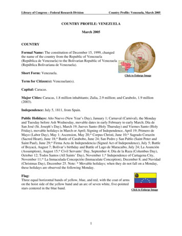
UNIT LOCATION / UNIT MOUNTINGUNIT LOCATIONFigure 3.3Combination Horizontal and Vertical Delivery UnitInstallationDANGERAppliances with power codes 01, 02, 04, 05, and 10 mustnot be installed where they may be exposed to a potentiallyexplosive or flammable atmosphere.1. Units should not be installed in atmospheres wherecorrosive fumes or sprays are present.2. Be sure no obstructions block air intake or air discharge ofunit heater.3. Locate horizontal delivery unit heaters so air streams ofindividual units wipe the exposed walls of the buildingwith either parallel or angular flow without blowing directlyagainst the walls. Heaters should be spaced so the airstream from one supports the air stream from anotherheater. See Figure 3.1.4. Columns, machinery, partitions, and other obstacles shouldnot interfere with air streams from unit heaters.5. Unit heaters installed in a building exposed to a prevailingwind should be located to direct a major volume of heatedair along the windward wall of the building.6. Large expanses of glass, or large doors that are frequentlyopened, should be covered by long-throw unit heaters suchas large horizontal delivery of “Power-Throw” unit heaters.7. Vertical delivery unit heaters should generally be located inthe central area of the space to be heated. Place horizontaldelivery units along the walls of the same building whereheat loss is usually greatest. See Figure 3.3.8. Arrange horizontal delivery units so they do not blowdirectly at occupants. Air streams from this type of unitshould be directed down aisles, into open spaces on thefloor, or along exterior walls.9. When only vertical delivery units are installed, they shouldbe located so exposed walls are blanketed by their airstreams. See Figure 3.2.Figure 3.1 - Horizontal Delivery Unit LocationFigure 3.2Unit Locations of Vertical Units In Narrow BuildingsUNIT MOUNTINGCAUTIONDo not install units below 8 feet measured from the bottom ofthe unit to the floor.Do not install unit above recommended maximum mountingheights. Height at which unit heaters are installed is critical.Maximum mounting heights for all units are listed in Table 4.1and the height dimensions are shown in Figures 4.3 through4.7. Maximum mounting heights for vertical models are givenfor units with or without optional air deflectors. The data inTable 4.1 is based on operating conditions of 2 lbs. steam or220 F entering water with 60 F entering air. When operatingconditions are other than those above, refer to Figure 4.2 formaximum mounting height correction factor. To obtain themaximum mounting at actual operating conditions, multiplythe appropriate factor from Figure 4.2 by the mounting heightin Table 4.1. The maximum mounting height for all units is thatheight above which the unit heater will not deliver heated airto the floor at standard rating conditions.Deflector MountingIf an optional air deflector has been furnished for vertical units,it is always shipped separately and can be attached to the unitbefore suspension. Vertical louvers for horizontal units andhorizontal louvers for “Power-Throw” units can also be addedand positioned before installation. Cone-jet and louver-typedeflectors must be attached with angle brackets and machinescrews to the bottom cover of the unit. Refer to mountinginstructions which are furnished with each deflector.Depending on supply or return piping arrangement, there isa possibility of interference between certain anemostat airdeflectors and piping on some vertical air delivery unit heaters.Check dimensions.1-550.253
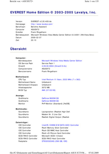
UNIT MOUNTINGTable 4.1 - Maximum Mounting Heights“Power-Throw”Type ➁ModelHeight–Ft.No.Std. L.O.T.Horizontal Type ➀ModelHeight–Ft.No.Std. �————————PT/PTN-279 ➁PT/PTN-333 ➁PT/PTN-385 ➁PT/PTN-500 ➁PT/PTN-610 �————————————22—Vertical Type with Deflectors ➁No �Ft.Height–Ft.No.Std. L.O.T. Std. L.O.T. Std. L.O.T.V/VN-42 ➁V/VN-59 ➁V/VN-78 ➁V/VN-95 ➁V/VN-139 ➁V/VN-161 ➁V/VN-193 ➁V/VN-212 ➁V/VN-247 ➁V/VN-279 ➁V/VN-333 ➁V/VN-385 ➁V/VN-500 ➁V/VN-610 ➁V-952 td. 131374141415150—With horizontal louvers opened 30 from the vertical plane. HSB units have top and bottom piping connections, HC units have side connections. All have copper tubes.V and PT models have copper tubes, VN and PTN models have cupronickel tubes.Mounting heights are maximum for heaters operating at standard conditions (2 lbs. steam or 220 F water with 60 F entering air). Heights listed for Louver or Cone-Jetare with deflectors in fully-opened position. Refer to Figure 4.2 for correction of mounting heights under other operating conditions. Maximum mounting height will bereduced as entering air temperatures exceed 60 F.➀➁Correction Factor "R"Figure 4.2 - Maximum Mounting Heights Correction 0220510230240Steam 40350360370Average Water Temp – FThese correction factors are to be used as multipliers to correct the maximum recommended mounting heights of unit heaters when operated with steam pressures otherthan 2 pounds or with water at other than average temperature of 220 F.Figure 4.3 - Horizontal Unit DeliveryFigure 4.4 - Vertical One-Way & Two-Way LouversHHFigure 4.6 - Vertical TrunconeFigure 4.3 Vertical Cone JetHHH41-550.25H
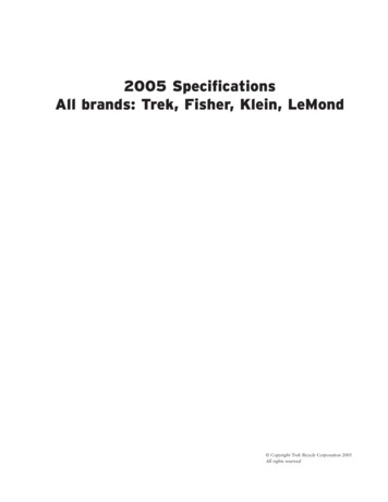
UNIT SUSPENSION / INSTALLATIONUNIT SUSPENSIONHorizontal delivery units, Model HSB/HC Series. All horizontaldelivery units, except Models HSB-18 and HSB-24, have twotapped holes (1/2"-13) in the top for unit suspension. HSB-18and HSB-24 models do not require independent suspension andare installed directly on their supply piping. Models HC have twotapped holes (HC 18-86 3/8"-16, HC 108-340 1/2"-13) in thetop for unit suspension. Piping support hangers or clamps arerecommended and should be placed as close to the unit heater aspossible. For other models, independent suspension can be madewith threaded rods, pipes, or ceiling hanger brackets. See Figure5.1.Vertical delivery units. Vertical delivery Models V/VN-42 throughV/VN-279 have four tapped holes (1/2"-13) in the top cover for unitsuspension. Unit suspension for these models can be made withthreaded rods, pipes or ceiling hanger brackets. Models V/VN333 through V/VN-952 are equipped with an angle-iron mountingbracket that has eight 5/8-inch diameter hanger holes permittinghook-hoisting and suspension with cables, if desired. A 1/2-inch Ubolt, 3-inch center can be inserted in the two holes at each end ofthe bracket to accommodate suspension with four threaded rods,pipes or hanger brackets.Power-Throw horizontal delivery units. “Power-Throw” units aredesigned for horizontal air delivery and are equipped with hangerbrackets for suspension. Three hanger brackets are supplied forModel PT/PTN-279, one on the front, and two on the rear panel forthree-point suspension. Only two hanger brackets are furnishedon the front panel of Models PT/PTN-333 through PT/PTN-952(for required four-point suspension use the two hanger bracketson the front panel and the two holes on the ends of the upperangle supports at the rear of the unit). Each hanger bracket has a5/8-inch diameter mounting hole for hook-hoisting and suspensionwith threaded rods, pipes, or cables.Note: A pipe hanger adapter kit as illustrated in Figure 5.1 isavailable as an accessory from Modine. The kit consists of twodrilled 3/4-inch I.P.S. pipe caps and two capscrews to facilitatethreaded-pipe suspension. One kit will mount a Model HSB 33340 or HC 108-340 horizontal delivery unit. Two kits are requiredto mount a Model V/VN vertical delivery unit.3.4.5.6.7.8.hot water systems, include a balancing valve in return line forwater flow regulation. A drain valve should also be providedbelow each unit heater to allow removal of water from theheating coil if located in an area subject to freezing.In steam or hot water systems, rapid air removal is requiredbecause entrained air is a cause of corrosion. Hot watersystems should be equipped with suitable air vent valves forrapid and complete removal of air at the high points and endsof both supply and return mains. Proper air venting for steamsystems can be achieved by use of a steam trap with aninternal air vent.Traps must be located below the outlet of the unit. Consulttrap manufacturer for specific recommendations. Each steamunit heater should be provided with a trap of sufficient sizeand capacity to pass a minimum of two times the normalcondensate released by the unit at the minimum differentialpressure in the system. Trap capacity is based on thepressure differential between supply and return mains. Steamsystems should be equipped with a float and thermostatictrap or an inverted bucket trap with an air bypass.It is advisable to use a pipe line strainer before each steamtrap draining a unit heater. This protection will reduce themaintenance of the steam trap. When strainers are used theyshould be installed between the unit heater and the trap andbe the same size as the trap tapping. In order to catch dirtand scale, the strainer should have a screen perforation sizesmaller than the trap orifices.On systems where the steam supply to the unit heater ismodulated or controlled by a motorized valve, a vacuumbreaker should be installed between unit outlet and the trap.If a vacuum breaker is used, it should be in conjunction witha float and thermostatic trap.Install a scale pocket at bottom of unit heater to collect dirtand scale as shown in illustrations. Pipe diameter must bethe same size as unit connections and about six inches long.Provide adequate pipe hangers, supports, or anchors tosecure the piping system independently of the unit heater.Electrical ConnectionsWARNINGFigure 5.1Unit Suspension1. Disconnect power supply before making wiring connectionsto prevent electrical shock and equipment damage.2. All appliances must be wired strictly in accordance withwiring diagram furnished with the appliance. Any wiringdifferent from the wiring diagram could result in a hazardto persons and property.3. Any original factory wiring that requires replacement mustbe replaced with wiring material having a temperaturerating of at least 105 C.4. Ensure that the supply voltage to the appliance as indicatedon the serial plate is not 5% greater than the rated voltage.CAUTIONPiping - See Figure 6.11.2.Branch piping to and from unit heater should include swingjoints to allow for expansion and contraction of the pipingwithout placing a strain on the unit heater element. On steamsystems, the branch piping should be taken off and returnedabove the centerline of the supply and return lines.Install pipe unions and shut-off valves in lines to and fromeach unit heater to allow maintenance or replacement ofunit without shutting down and draining entire system. For1. Do not install units below 8 feet measured from the bottomof the unit to the floor.2. Do not reuse any electrical component which has beenwet. Such component must be replaced.3. Ensure that the supply voltage to the appliance, as indicatedon the serial plate is not 5% less than the rated voltage.1.Installation of wiring must conform with local buildingcodes, or in the absence of local codes, with the NationalElectric Code ANSI/NFPA 70 - Latest Edition. Unit must beelectrically grounded in conformance to this code. In Canada,wiring must comply with CSA C22.1, Electrical Code.51-550.25
INSTALLATION / OPERATIONFigure 6.1 - Suggested Piping ArrangementsHot Water SystemsHorizontal Unit Heater Connected toOverhead Hot Water MainsVertical Unit Heater Connected toLower Hot Water MainsSteam SystemsUnit Heater Connection for Low-PressureSteam — Open Gravity or Vacuum Return SystemUnit Heater Connection for High Pressure SteamElectrical Connections (Cont.)OPERATION2.Electric wiring must be sized to carry the full load amp drawof the motor, starter, and any controls that are used withthe unit heater. All units with power codes 04, 05, 09,
Modine Manufacturing Company. Refer to the rating plate . troubleshooting guide listed in Table 15.1, refer to the applicable sections of the manual. . unit heater. 3. Locate horizontal delivery unit heaters so air streams o