Transcription
MSD Power Grid System ControllerPN 7730/77303ONLINE PRODUCT REGISTRATION: Register your MSD product online. Registering your productwill help if there is ever a warranty issue with your product and helps the MSD R&D team createnew products that you ask for! Go to www.msdperformance.com/registration.Parts Included:1 - System Controller, PN 7730 / PN 773031 - 4Gb SD Card1 - Micro-USB Cable1 - MSD View CD-Rom1 - Fiber Optic Plug1 - CAN Terminator Cap1 - Power Cable-Loose1 - Mag Cable1 - 2-pin Legacy Cable1 - Main Cable Loose1 - Parts BagAccessories (Purchased Separately):Inductive Cam Sync Kit, PN 7555Hub Connector, PN 7740 / PN 77403Slew Rate and Time Based Rev Limiter, PN 7761Boost Retard Module, PN 7762Manual Launch Controller, PN 7751Racepak V-Net Tee9” - 280-CA-VM-T00918” - 280-CA-VM-T01836” - 280-CA-VM-T036WARNING: During installation, disconnect the battery cables. When disconnecting, always removethe Negative cable first and install it last.Note: Solid core spark plug wires cannot be used with an MSD Ignition Control.Note: A crank trigger is recommended to supply the input signal to the Power Grid Ignition System toensure the most precise timing and rpm control.OPERATIONDIGITAL OPERATIONThe MSD Power Grid System Controller uses a high speed RISC microcontroller to control the ignition’soutput while constantly analyzing the various inputs such as launch, burnout, and step wires; trigger signals,rpm, and CAN-Bus data. The high speed controller can make extremely quick updates to the ignition output,timing, and rpm limits while maintaining /- 0.1 timing and /- 1 rpm resolution. The circuits and controller ofthis system have been designed for superior protection against Electro Magnetic Interference (EMI).The Power Grid System Controller, PN 7730 / PN 77303, is designed to be used with the Power Grid-7Ignition Control, PN 7720. This is a high output CD ignition control. The Ignition System allows for the SystemController to be mounted on top of the Power Grid-7 to save space and provide a neat, compact installation.The System Controller can also be used with other MSD Ignitions such as the 7AL-2, MSD 8-Plus, and thePro-Mag series. In order to use the rev limiting features of the System Controller the paired ignition musthave a built-in Soft Touch Rev Control that uses plug-in RPM modules. Pages 10-12 show wiring diagramsfor a variety of different ignition options.MSD WWW.MSDPERFORMANCE.COM (915)855-7123 FAX(915)857-3344
2INSTALLATION INSTRUCTIONSWIRING n4-PinConnector(to PN 7720or PowerCable if notused withPN 7720)BLACK16GROUNDIgnition supply Ground wire. Connect to battery negative (-) terminalor engine block.ORANGE17BATT POWER Battery supply wire. Connects to battery positive ( ) terminal or batteryjunction. Note: Do not connect to the alternator.YEL/WHT33TRIGGER OUT Trigger output for electronic ignition amplifiers.RED34POWER OUTOn/Off switch wiring. This wire supplies switched 12V power to the7720.RED15IGN12V switched (Ignition)GRAY18TACHTach output. This wire will provide a 12 volt square wave tach signal.WHITE32POINTS INTrigger input from electronic ignition amplifiers, an ECU’s trigger orpoints.YELLOW1SHIFT LIGHTShift Light output wire. It can handle up to 3 amps continuous to groundwhen enabled.LT BLUE4BURN OUTBurnout Rev Limit. When 12 volts are applied the Burnout Rev Limit isactive. This disables the Slew Rate rev limits and overrides other rev limits.It is recommended to have this wire switched from an outside source, suchas the crew chief before the burnout and while staging the car.DK BLUE21LAUNCHThis wire activates the Launch Rev Limit and is the main reset wire forseveral features of the Ignition. When 12 volts are applied to this wire itwill activate the Launch Rev Limit. It also resets the shift light, the gearindicator to first gear, the Launch Retard curve and select Gear 1 curve.When 12 volts is removed, the Launch Time begins as does the Gear 1curve. When 12 volts are applied the Slew Rate Rev limit will be disabledas well as the Time-Based Rev Limit curve.PINK22STEP 1Step 1 retard enabled with 12 volt input AND above Step 1 Rpm valueOR Gear 2 Select.VIOLET5STEP 2Step 2 retard enabled with 12 volt input AND above Step 2 Rpm valueOR Gear 3 Select.TAN23STEP3Step 3 retard enabled with 12 volt input AND above Step 3 Rpm valueOR Gear 4 Select.LT GREEN 6STEP4Step 4 retard enabled with 12 volt input AND above Step 4 Rpm valueOR Gear 5 Select.GREENSTEP5Step 5 retard enabled with 12 volt input AND above Step 5 Rpm valueOR spool rev limiter.BRN/WHT 19RPM SWRPM/Time switch output wire. It can switch up to 3 amps continuousto ground when enabled.YELLOW7RELAY LOYELLOW24RELAY HINetwork Ignition Mode: Cam sync output to Racepak systems forindividual cylinder timing.or3-PinConnectorGREENVIOLETBROWN8925MAGMAG SHIELDThis is a magnetic pickup, 2-pin connector. Plugs into an MSDDistributor or Crank Trigger pickup. Violet is positive, Green isnegative. Note: When this connector is used, the white POINTS INwire is not connected. Brown connects to ground.RacepakAssemblyWHITEBLACK11VNET HIVNET LOCommunicates data acquisition information with RacePak system.Only used to plug into VNet.6-PinConnector(to Hub/Modules)REDBROWNREDBLACKBLACK1327293031MSD CAN HISHIELDPOWER OUTMSD CAN LOMSD CAN GNDSupplies 12V switched power to add on module units.Alsocommunicates between modules and Power Grid System Controller.This connector plugs into CAN-Bus hub, PN 7740/77403 to addadditional modules. If not used plug in a Termination Cap, PN 7741.LOOSEWIRES2-PinConnector(Legacy)MSD 10Legacy Ignition Mode: Rev limiter output to legacy ignition.WWW.MSDPERFORMANCE.COM (915)855-7123 FAX(915)857-3344
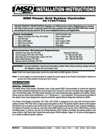
INSTALLATION INSTRUCTIONS3YELLOW - SHIFT LIGHTGRAY - TACHBRN/WHITE - RPM/TIME SWITCHV-NETCABLELT. BLUE - BURN OUTBLUE - LAUNCHPINK - STEP 1VIOLET - STEP 2TAN - STEP 3LT. GREEN - STEP 4GREEN - STEP 5SWITCHED IGNITION 12VRED - 12V SW OUTBLACK - BATTERY (-)ORANGE - BATTERY 12VWHITE - POINTS OUTWHITE - POINTS INLEGACY IGNITIONMSDCANMAG PICKUPCONNECTORFigure 1 Wires of the Power Grid System Controller.RED - 12V SW OUTBLACK - BATTERY (-)ORANGE - BATTERY 12VWHITE - POINTS OUTYELLOW - SHIFT LIGHTGRAY - TACHV-NETCABLEBRN/WHITE - RPM/TIME SWITCHLT. BLUE - BURN OUTBLUE - LAUNCHWHITE - POINTS INPINK - STEP 1VIOLET - STEP 2TAN - STEP 3LT. GREEN - STEP 4GREEN - STEP 5SWITCHED IGNITION 12VmaleHEAVYRED TO BATTERY POSITIVEHEAVY BLACKTO BATTERY NEGATIVE -LEGACY IGNITIONMSDCANMAG PICKUPCONNECTORNOTE: SEE PAGES 10-12 FOR SCHEMATICSSHOWING INSTALLATION TO OTHERMSD IGNITION CONTROLS.- BLACK ORANGEFigure 2 Wiring the Power Grid.MSD WWW.MSDPERFORMANCE.COM (915)855-7123 FAX(915)857-3344
4INSTALLATION INSTRUCTIONSMOUNTINGThe Power Grid System Controller should be mounted in asturdy, dry location that does not expose the unit to extremeheat. It is designed to be mounted on top of the PN 7720Power Grid Ignition. Be sure to mount the Power Grid SystemController so the USB connector and Micro-SD card areaccessible. The unit comes with thread-turning (aka. Selftapping) screws that will cut into the walls of the pre-drilledholes on the top corners of the Power Grid-7. If the Power GridSystem Controller, PN 7730 / PN 77303, is not being mountedon top of the Power Grid-7 the unit should be secured withthe supplied hardware.Figure 3 MountingNote: Insecure or otherwise improper mounting of the unitcould result in damage or failure. Always make surethe unit is dry, avoids unnecessary excess vibration,and is not exposed to extreme heat.MSD VIEWThe MSD View software controls all of the functionality of the Power Grid System Controller. The followinginformation gives a brief explanation of each function or feature in the system as well as the settings thatcontrol it. While using the program, hover the mouse over a Function to display a brief explanation.When the system controller is connected to a PC via USB MSD View will automatically recognize it and loadthe settings stored in it.Note: Ensure that MSD View is installed on the PC prior to connecting the Power Grid Ignition Controller.INSTALLATION OF THE VIEW SOFTWARE1. Insert the installation CD Rom into the CD drive, wait up to 30 seconds, the CD will auto run, IF THISDOES NOT OCCUR:Locate and open the CD Drive.Double click on the Setup file.2. Select “Click here to Install Version X.XX”.3. Once loaded, your monitor will have an MSD View X.XX logo. Accept the agreement. Drive the installationto your program files folder, press the enter key. The installation will complete, select OK.4. A window will be opened with two aliases, double-click on the MSD View alias to launch the software.5. Connect the system controller via USB. If the software does not recognize the controller and auto-connect,manually select the Power Grid in the popup window and click Connect.Note: The View Software can be downloaded from www.msdignition.com.SAVES AND TRANSFERSUsing the Power Grid System Controller changes are in real time if the computer is linked to the ignition.You can create and save numerous files on your PC and transfer them for testing purposes or to use forvarious locations and conditions.The following instructions will go through a general description of the use of the Power Grid System Controlfollowing the tab system that you will see in the software.MSD WWW.MSDPERFORMANCE.COM (915)855-7123 FAX(915)857-3344
INSTALLATION INSTRUCTIONS5PROGRAMMABLE FEATURES AND SETTINGS:GENERALThese are the most basic settings of the system. They will need to be set the first time the system is installedin a vehicle.Number of Cylinders: This tells the system the number of cylinders. Must be selected correctly for propertiming and rev limiting.Maximum Timing Reference: This is the advance that is set with a locked distributor or crank trigger. Thesystem controller will use this as its base for all timing marks and can never advance past the pre-setpoint. It is critical that this advance is set properly.Note: When using EFI the max timing reference and the main timing must be the same number.Number of Gears: This tells the system the number of gears used in the transmission. This information canbe used a variety of ways depending on the functions and modules used in the system.Ignition Type: Found under General Settings, this option allows a user to select between using the PowerGrid Ignition, PN 7720, or one of the MSD legacy ignitions.DIAGNOSTIC LED INDICATORThe LED is located on the far right side of the Power Grid Controller, next to the USB/SD Card cover. ThisLED allows the user to quickly determine if; all systems are normal, data is being recorded or if there areany active Alerts.OFFORANGE for 1 SecondORANGE for 10 SecondsORANGE - blinkingGREEN - blinkingRED - blinkingGREEN - solidRED - solid– Unit is turned off– Power ON LED test– ARC Module (PN 7761) has been connected (*see notes below)– Data recording in process– Input (crank pickup or Points wire) triggered; below 500 rpm, no active Alerts– Input (crank pickup or Points wire) triggered; below 500 rpm, 1 or more activeAlerts– Running; above 500 rpm, no active Alerts– Running; above 500 rpm, 1 or more active Alertys*NOTE: Many racing organizations (NHRA, IHRA, etc.) use an MSD Power Grid test tool that can check forthe following settings:1. ARC Module - indicates if an ARC module (PN 7761) has been connected (Holds connection indicatorfor the next 60 minutes of engine run time after the ARC codule has been disconnected)2. Safety Limiter - the RPM that the engine will be limited to if it exceeds the Safety Run Time limit.3. Safety Run Time - the run time, in seconds, after the Launch input (Blue wire) has been released. Activatesthe Safety Limiter when timer reaches 0 seconds.4. Part Numbers - lists the part numbers of any MSD compatible module connected to the Power Grid system.5. Over Boost - Boost pressure ignition cut off value of the MSD Boost Controller (PN 7763). If connected.CAMSHAFT SYNCHRONIZATIONThis is used only in applications where the individual cylinder timing is going to be used. The fiber opticconnector communicates when the #1 cylinder fires. With this information, the controller knows which cylinder is being fired allowing for the individual cylinder timing capabilities. Only the MSD Fiber Optic Inductive Pickup Kit, PN 7555 will work for this system. Cam-sync’s cylinder #1 identification is also used in thedata acquisition recordings.MSD WWW.MSDPERFORMANCE.COM (915)855-7123 FAX(915)857-3344
6INSTALLATION INSTRUCTIONSGEAR SHIFTIn the Gear Shift selection the user can set items such as launch and shift delay so that the system will nothave a false shift detected immediately after launch or a shift should there be an rpm drop for any other reason.Launch Delay: The amount of time in seconds after the launch that the system will ignore an rpm drop toprevent false shift detection. This can be set from 0.00 to 10.00 in .01 second increments.Shift Delay: The amount of time in seconds after sensing a shift that the system will ignore an rpm drop toprevent false shift detection. This can be set from 0.00 to 10.00 in .01 second increments.1- 2 Shift: By setting the rpm drop the user tells the system how to sense when the car is being shiftedduring a run. The setting is controlled by a drop down list with rpm from 200 – 1,500 or can be setto be activated by a Step Retard wire instead. The number of shifts that is shown is controlled by thenumber of gears the system is set to in the Settings – General tab.SHIFT LIGHTUsing the Shift Light controls opens a variety of options designed to help make sure the light is exactly asdesired. The shift light setting can be set by single rpm increments. In this control tab, each value can beentered to the exact rpm desired and the light’s intensity can be adjusted so that it is visible without blinding.The number of gears that appear on this tab will be auto-populated by the program after the number of gearsis set in the general settings. This can also be used with a relay as a transmission shifter. The maximumcurrent for this circuit is 3 amps.Light Intensity: This percentage setting controls brightness of the shift light for easy use in both day andnight racing. If being used for anything other than shift light control, the intensity must be 100%.Power-On Test: Normally set to on but can be turned off if desired. The power-on test turns the shift light onas soon as the controller receives power to show that the circuit is complete and working.Launch Light: The Shift Light will turn on if the engine rpm is between the launch low limit and the launchhigh limit. The light will blink if rpm is above the launch high limit.Gear 1-5: A setting can be adjusted for each individual shift. To do this enter the engine RPM that shouldturn the Shift Light ON for each gear.OUTPUT SWITCHWhen the switch is activated it will supply ground to a circuit in order to turn an item on by time and/or rpm.The circuit can maintain up to 2 continuous amps. If more than 2 amps is needed a relay is recommended,PN 8961.To activate or deactivate this circuit the system must see a programmed time and/or rpm setting which isprogrammed in the Settings – Output. Using both On and Off values will set a window to control the switch.The output will only be activated while within the set window and will be deactivated as soon as one or bothsides of the windows are not met. All parameters must be met for the output switch to be activated. Forexample, if values are entered for both RPM On and Activation Point (timed on) then both of those valuesmust be reached before the switch is activated. The rpm function becomes active and the time function beginscounting after the Dark Blue launch wire is released.Note: If using the time activation function a duration MUST be set above 0.00 or the switch will not beactivated by time.IGNITION TIMINGThe user can set the timing from 0 - 60 BTDC. However, actual timing will never advance past the maximumtiming reference nor will the timing retard more than 30 from the max timing reference. MAX and MIN timinglines will be displayed for convenient reference in the main engine timing tab. (Those lines can be turned offby unchecking them in the upper left column.)Note: When using EFI the max timing reference and the main timing must be the same number.MSD WWW.MSDPERFORMANCE.COM (915)855-7123 FAX(915)857-3344
INSTALLATION INSTRUCTIONS7Engine timing cannot exceed the maximum timing reference. In order to advance timing, the main timingmap must be set below the maximum timing reference. I.E. If the crank trigger is at 40 and the main timingmap is set to 35 there will be up to 5 of advance available.ENGINE TIMINGUsing MSD View software, an entire timing curve can be mapped. The map specifies the actual enginetiming. The Power Grid will retard the input trigger to obtain the correct engine timing. The maximum timingreference must be set properly for correct engine timing. These maps include changes in 50 rpm incrementsand timing changes down to 0.1 degrees. A maximum of 30 points can be set per map.This map will show all engine timing maps that are drawn based on rpm values such as timing curves pergear. The information for all of these maps is accumulative in the software. In order to edit a particular timingcurve the user must go into the proper tab per function.Start Retard: As part of the general engine timing curve, users can specify a start retard. While each engineresponds differently, the typical recommendation for a start retard is to to pull out 10 from 0 - 600rpm. A variety of other ideas can be applied to a start retard, including ramping timing in as enginerpm climbs. Use of such techniques is at the discretion of the user.GEAR CURVESThis program provides the ability to modify the timing curve for each gear. One curve can be created for eachgear, up to six, from 0 – 15,000 rpm in 0.1 increments for every 50 rpm. You can program up to 30 differentpoints on each Gear Curve. The number of gears shown and how a shift is detected are dependent on theselected values in the Settings tab.In the Ignition Timing – Gear Curves tab, an individual curve is plotted for each gear. Each change made for thegear curves references off of the Main Timing curve are set in the Engine RPM tab, not off of the max timingreference. Gear curves are NOT cumulative; i.e. Retarding 1 in 2nd gear does not affect 3rd gear settings.Note: The gear curves are independent of each other. In order to make progressive changes, one gear’sstarting point must match the final timing of the previous gear’s curve. Leaving a gear curve uneditedwill result in normal timing for that gear regardless of other gear curves ahead of or behind it.INDIVIDUAL CYLINDER TIMINGNote: To control ICT an inductive pickup, PN 7555, is required.To accomplish timing changes per cylinder the engine’s firing order must be entered first. Firing order isprogrammed in the tab Ignition Timing – Individual Cylinder – Firing Order by numbering the order into theValue column. Many common firing orders can also be imported from a database within the software; to doso simply go to File Import and open the “firing order” folder where an engine description can be selected.Similarly, if an engine uses a firing order not included in these options the settings can be exported to besaved in the same file.After the correct firing order is entered individual cylinder timing can be created by editing rules. Up to 10rules can be entered to control various aspects of timing for a single cylinder at a time. Each rule has six(6) values that can be controlled; Cylinder, Retard/Advance, Timing, From Gear, Delay, and Ramp Time. Tomake a rule the first four control values must be entered, Delay and Ramp Time may be left at the default of0 if desired. When timing is changed on an individual cylinder, in order to bring the cylinder back to originaltiming an equivalent amount of timing must be used to offset (DO NOT use 0 ). I.E. If cylinder two is retardedby 3 in RULE 1, in order to put the timing back in the cylinder must be advanced in a later rule by 3 .Cylinder: Double click this value to select the cylinder for which timing is to be altered.Retard / Advance: Enter whether timing will be Retarded or Advanced. After using this option timing changeswill always be entered as a positive number.Note: Engine timing cannot exceed the maximum timing reference. In order to advance timing, the maintiming map must be set below the maximum timing reference. I.E. If the crank trigger is at 40 the maintiming map is set to 35 there will be up to 5 of advance available.MSD WWW.MSDPERFORMANCE.COM (915)855-7123 FAX(915)857-3344
8INSTALLATION INSTRUCTIONSTiming Change: Enter the amount of timing that is to be retarded or advanced. This value will always be apositive number, regardless of whether advance or retard is desired.From Gear: This setting determines from which gear the timing change will become active. If gear one isselected the timing change will be active at all times unless a delay is used.Delay: This is the time, in seconds, that will pass prior to initiating the timing change after the proper gearchange. This setting defaults to 0.0 but can be taken up to 5.0 seconds. If a timing change is desiredduring an entire run, but not other times the engine is running, this setting should be entered as 0.1 sec.Ramp Time: The amount of time it takes for the Individual Cylinder Timing to be fully engaged. During thistime the controller will ramp the timing change from the starting point to full timing.Note: Changes made in Individual Cylinder Timing are cumulative. If a cylinder’s timing is to be altered for aduration of time two rules must be made, one to initiate the change and another to reverse the changeat the appropriate time.LAUNCH RETARD (TIMING BY TIME)This function allows a user to set an engine timing curve based on the run time from launch (release of thedark blue wire). It can be programmed from 0 to 20 in 0.1 increments. Up to 30 trace points can be set per0.01 sec. across the available 10 seconds. When the Launch wire is active, the retard value is the placementof the first dot. When 12 volts are removed from the Dark Blue wire the engine timing will follow the prescribedcurve added to the base timing set at the engine RPM map.STEP RETARDSThere are five step wires that control each of the corresponding step retards. These retards can be set sothat they are not active until a specified rpm is reached even if the wire receives voltage. Using this systema step can activate as soon as the trigger wire receives 12 volts or after the engine reaches a specific rpmwith 12 volts at the trigger wire. Once the retard is activated, timing can be changed in a single step or beramped in over a period of time. The retard can also be turned off in a single step or ramp after a prescribedtime after power is removed.Step 1PinkStep Retard Activation WiresStep 2Step 3Step 4VioletTanLight GreenStep 5GreenNote: These wires can also be used as Gear Select Indicators. See page 5.Note: The Step-5 wire may be used as a Spool Rev Limiter. When using this wire for a retard and not a SpoolRev Limiter, the rev limit setting must be set above the max rev setting.Activation through Wiring: Each step is activated by applying 12 volts to the corresponding wire. Whenmultiple step retards are enabled at the same time the retard amounts are added together. Themaximum retard allowed by the system is a total of 30 (including other retard amounts from a launch,boost, gear retard, etc).Activation through RPM: Each step retard can also be activated through rpm. In order to achieve this,12 volts must still be applied to the corresponding step retard, and an rpm must be entered in therespective step retard control. When 12 volts is applied, the retard will not activate until the rpm valueis reached. Note that the retard will remain active until the rpm drops back below the set value. Thestep retard is added to all other retards in the system, including other active steps until it is deactivated.Each of the five step retards has its own tab under the Ignition Timing – Step Retard tab. Within the individualtabs there are controls for the step retard.Timing Retard: This is the amount of timing that will be retarded while this step is active. The timing canbe adjusted in 0.01 increments.Engine RPM: When this setting is used the engine must be above the prescribed RPM before the stepretard will be activated.On Ramp: The amount of time it takes for the step retard to retard the full amount. During this time thecontroller will ramp the timing retard from the starting point to full step retard.MSD WWW.MSDPERFORMANCE.COM (915)855-7123 FAX(915)857-3344
INSTALLATION INSTRUCTIONS9Off Delay: This feature will set a time based delay to deactivate the step retards. The Off Delay is designedto keep the timing retarded after the wire is deactivated. This setting defaults to 0.0 sec but can betaken up to 5.0 sec by the user.Off Ramp: The amount of time the system takes to turn the step retard off once power is removed from thestep wire and any delay is complete. During this time the controller will ramp the step retard out.Note: If you prefer to activate the step retards through the activation wires alone without considering rpm thesetting for rpm should be left at the default of 0.SHIFT RETARDUsing MSD View, a retard can be implemented momentarily to help maintain traction immediately after ashift. To do this, simply enter the amount of timing retard desired and the length of time the retard should beactive for each shift. Whether using an rpm drop or a step retard activation wire for a trigger, as soon as thesystem detects a shift it will retard the timing for the prescribed amount of time.REV LIMITERA variety of different rev limits can be programmed per individual vehicle needs. The actual rev limiter willnever exceed the maximum rev limiter.Burnout Rev Limiter: This limit is activated when 12 volts are applied to the Light Blue wire. It is adjustablefrom 1,000 to 15,000 rpm. Note that the Slew Rev Limiter is disabled by the Burnout Limit.Launch Rev Limit: This limit is activated when 12 volts are applied to the Dark Blue wire. It is adjustablefrom 1,000 to 15,000 rpm.Latching: When this setting is enabled engine rpm must be below 7/8 of the launch limit setting while 12volts is applied to the Dark Blue wire to engage the Launch Limiter. This allows clutch cars to wirethe Dark Blue wire directly to the clutch switch without the need to use a relay. If Latching is disabled,the Launch Rev Limiter will be engaged anytime the Dark Blue wire receives 12 volts (such as duringeach shift) regardless of engine rpm.Maximum Rev Limiter: This is the overrev limit to help protect the engine from damage.Spool/Step 5 Rev Limiter: This program gives turbo cars a fourth rev limit to help the engine spool theturbo prior to the launch. It is active when 12 volts is applied to both the Light and Dark Blue wiresat the same time or when using the Step 5 retard wire. (The Step 5 wire can allow for activating theSpool rev Limiter without activating the line-lock.) It is adjustable in 50 rpm increments from 1,000to 15,000. Default is 12,000 rpm.Safety Run Time Rev Limiter: Using two settings a safety limiter can be activated in case of incident. If forany reason the engine is still revving after the set amount of time since the launch limiter is released,this feature will lower the rev limit to a user specified rpm over 2 seconds. This will help anytime thethrottle is open much longer than it should be, such as a stuck throttle linkage or an accident.Users have two options to activate the Safety Run Time countdown; the Launch limiter, or the SafetyRPM Start. In either case the Dark Blue wire must be activated so that time down can start uponits release. Many users will activate the Safety countdown by bringing the engine up on the limiter.Users who do not wish to use the launch rev limiter can activate the safety run time countdown bytaking the engine rpm equal or higher than the Safety RPM Start setting. This setting act only as acountdown activator and has no rev limiting ability.DATA ACQUISITIONThe data recorder on the Power Grid System Controller comes with a 2GB micro SD card which will easilyhold more than an entire event’s worth of data. Within the settings for data acquisition on the system controllerthere are four tabs that provide options for when and what data is recorded. If a new micro-SD card is neededor wanted for any reason it is important to get a Class 6 or higher at the minimum, NOT all micro-SD cardswill work. If there is question as to whether an SD card will work test recording should be done prior to a run.The Power Grid System Controller will also easily send the data it records to compatible Racepak dataacquisition systems. To connect the two systems simply plug the included VNet connector into an availablespace on the on the Racepak system. To be compatible the user must have a Racepak Data VNet Loggerusing DatLink Software v3.7.4 or higher. Default settings will send 13 channels of data to the RacePak system.MSD WWW.MSDPERFORMANCE.COM (915)855-7123 FAX(915)857-3344
10INSTALLATION INSTRUCTIONSSettings:This tab has two possible adjustments. The first setting allows a user to turn the data recording off, ifdesired. The second control tells the system what to do if the SD card is full. This setting allows thesystem to either stop recording or begin to write over data with the lowest recording name. By defaultthe system is on and will overwrite once the memory is full.Channels:Each available data trace within the PN 7730 / PN 77303 is listed in this tab. Each trace can bedisabled individually in order to remove unneeded traces and generate smaller files. The Ignition Inchannel and the Igniti
YELLOW 1 SHIFT LIGHT Shift Light output wire. It can handle up to 3 amps continuous to ground when enabled. LT BLUE 4 BURN OUT Burnout Rev Limit. When 12 volts are applied the Burnout Rev Limit is active. This disables