Transcription
GRID-CONNECTEDPV SYSTEMSSYSTEM DESIGN GUIDELINES
AcknowledgementThe development of this guideline was funded through the Sustainable Energy Industry Development Project(SEIDP). The World Bank through Scaling Up Renewable Energy for Low-Income Countries (SREP) and the SmallIsland Developing States (SIDSDOCK) provided funding to the PPA as the Project Implementation Agency for theSEIDP. The guidelines have been developed by Global Sustainable Energy Solutions with the support of Dr HerbertWade and reviewed by PPA and SEIAPI Technical Committees.These guidelines have been developed for The Pacific Power Association(PPA) and theSustainable Energy Industry Association of the Pacific Islands (SEIAPI).They represent latest industry BEST PRACTICE for the design of Grid Connected PV Systems Copyright 2019While all care has been taken to ensure this guideline is free from omission and error, no responsibility can be taken for the use ofthis information in the design of any grid connected PV System.
Table of Contents1. Introduction. 12. Standards Relevant to Design of Grid Connected PV Systems. 53. Steps when Designing a Grid Connected PV System. 64. Site Visit. 75. Selecting a Solar Module. 86. Choosing an Array Structure. 87. Energy Output of a Solar Array. 97.1 Solar Irradiation. 97.2 Effect of Orientation and Tilt. 107.3 Shading of Array. 117.4 Factors Affecting the Solar Module’s Power Output. 117.5 Derating Solar Modules Power Output. 168. Inverter Selection. 178.1 How Many Inverters?. 178.2 Selecting the Size of Inverter. 188.3 Matching Array Power to the Inverter. 198.4 Matching Array Voltage to the Inverter. 208.4.1 Minimum Number of modules in the string. 218.4.2 Maximum number of modules in the string. 258.5 Matching Array Current to the Inverter. 289. Electrical Losses in the Grid connected PV System. 2910. Energy Yield. 3010.1 Effect of Shading. 3111. Specific Yield. 3112. Performance Ratio. 3213. Providing a Quotation. 33Appendix 1: Temperature Conversion Tables.34Appendix 2: Solar Irradiation Data. 35Appendix 3: Effect on Irradiation Due to Orientation and Tilt Angle. 40
List of FiguresFigure 1: Components of a Grid-Connected PV System-String Inverter. 1Figure 2: Components of a Grid-Connected PV System-Module Inverter. 2Figure 3: Ground Mounted Solar Array. 2Figure 4: Showing Inverter and Frame. 3Figure 5: Isolators and Surge Protection Devices. 3Figure 6: Array on House Roof. 4Figure 7: Household Installation. 4
List of AbbreviationsA summary of the main acronyms and terms used in this document is listed below:ACAlternating CurrentASAustralian StandardsDCDirect CurrentENEuropean Standards (European Norms)IECInternational Electrotechnical Commission.KWpKilowatt PeakKWhKilowatt HourLED Light-emitting DiodeMP Maximum PowerMPPMaximum Power PointMPPTMaximum Power Point TrackerNECNational Electrical CodeNZSNew Zealand StandardsPNGPapua New GuineaPSHPeak Sun HoursPV PhotovoltaicSTCStandard Test ConditionsULUnderwriters Laboratories
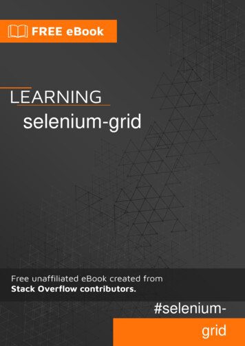
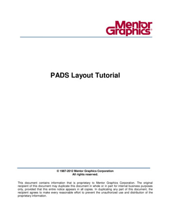
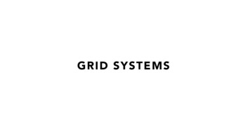
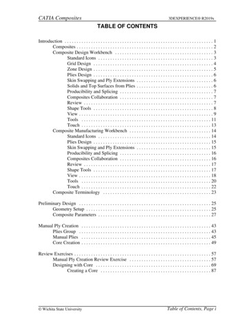
1. IntroductionThis document provides an overview of the formulas and processes undertaken when designing (or sizing) a gridconnected PV system.This document provides the minimum knowledge required when designing a grid connected PV system. Designcriteria may include:- Specifying a specific size (in kWp) for an array;- Available budget;- Available module mounting space;- An annual kWh delivery goal such as wanting to zero the owner’s annual electricalusage from the grid;- Wanting to reduce the use of fossil fuel in the country or meet other specific customerrelated criteria.Whatever the final design criteria, a designer shall be capable of:- Determining the energy yield, specific yield and performance ratio of the grid connected PV system.- Determining the inverter size and quantity based on the size andnumber of the panels in the array.- Matching the array/panel configuration to the selected inverters: Maximum voltage and voltage operating window; Maximum allowable d. input power rating; and Maximum dc input current rating.A system designer will also determine the required cable sizes, isolation (switching) and protection requirements. Thisinformation is included in the companion guide titles: Installation of grid connected PV systems.Figures 1 & 2 show 2 types of typical interconnection of a grid connected PV system.Examples of the individual components are shown in Figures 3 to 7.GridArrayInvertersMetersFigure 1: Components of a Grid Connected PV System-String Inverter1 Design Guideline for Grid Connected PV Systems
MicroInvertersGridArrayMetersFigure 2 : Components of a Grid Connected PV System- Module InverterFigure 3: Ground Mounted Solar arrayDesign Guideline for Grid Connected PV Systems 2
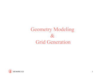
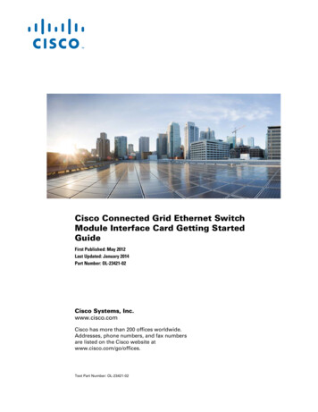
Figure 4: Showing Inverter and FrameFigure 5: Isolators and Surge Protection Devices3 Design Guideline for Grid Connected PV Systems
Figure 6: Array on House RoofFigure 7: Household InstallationNotes:1. IEC standards use a.c. and d.c. for alternating and direct current respectively while the NEC uses ac and dc. Thisguideline uses ac and dc.2. In this document there are calculations based on temperatures in degrees centigrade ( C). The formulas usedare based on figures provided from solar module manufactures where the temperature coefficients are generallyexpressed in C in degrees while there are some from the USA that have used degrees kelvin (K). A one-degreechange in C is equal to a one-degree change in K. So if the module manufacturer provides the temperature coefficientin K, just change the K to a C.If your local temperatures are given in Fahrenheit degrees, to use the formulas shown in this guideline, you mustconvert F to C. For your convenience in making that conversion, Appendix 1 is a table to convert from F to Cfrom 32 F to 127 F (0 C to 53 C). Use the appropriate Fahrenheit number in a F column and use the number in theadjacent C column in the formulas given in this guideline.Design Guideline for Grid Connected PV Systems 4
2. Standards Relevant to Design of Grid Connected PV SystemsSystem designs should follow any standards that are typically applied in the country or region where the solarinstallation will occur as well as any additional standards specific to the island country where the installation islocated. The following are the relevant standards in Australia, New Zealand and USA. They are listed because somePacific island countries and territories do follow those standards. These standards are often updated and amended sothe latest version should always be applied.In Australia and New Zealand, the relevant standards include:- AS/NZ 3000Wiring Rules.- AS/NZS 3008Electrical Installations-Selection of Cables.- AS /NZS 4777Grid Connection of energy systems by Inverters.- AS/NZS 5033Installation and Safety Requirements of PV Arrays.- AS/NZS 4509Stand-alone power systems (note: some aspects of these standardsare relevant to grid connect systems).- AS 3595Energy management programs.- AS 1768Lightning Protection.- IEC 61215Terrestrial photovoltaic (PV) modules -Design qualification and type approval IEC 61215-1Part 1: Test requirements IEC 61215-1-1Part 1-1: Special requirements for testing of crystalline siliconphotovoltaic (PV) modules IEC 61215-1-2 IEC 61215-1-3 IEC 61215-1-4Part 1-2: Special requirements for testing of thin-film CadmiumTelluride (CdTe) based photovoltaic (PV) modulesPart 1-3: Special requirements for testing of thin-film amorphoussilicon based photovoltaic (PV) modulesPart 1-4: Special requirements for testing of thin-film Cu(In,GA)(S,Se)2 based photovoltaic (PV) modules IEC 61215-2- IEC 61730Part 2: Test ProceduresPhotovoltaic (PV) module safety qualification. IEC 61730-1Part 1: Requirements for construction. IEC 61730-2Part 2: Requirements for testing.- IEC 62109Safety of power converter for use in photovoltaic power systems. IEC 62109-1Part 1: General requirements. IEC 62109-2Part 2: Particular requirements for inverters.5 Design Guideline for Grid Connected PV Systems
In USA the relevant codes and standards include:- Electrical Codes-National Electrical Code and NFPA 70: Article 690:Solar Photovoltaic Systems. Article 705:Interconnected Electric Power Production.- Building CodesICC, ASCE 7.- UL 1703Flat Plate Photovoltaic Modules and Panels.- IEEE 1547Standards for Interconnecting Distributed Resources withElectric Power Systems.- UL Standard 1741Standard for Inverter, converters, Controllers and InterconnectionSystem Equipment for use with Distributed Energy Resources.- UL 62109:Standard for Safety of Power Converters for Use inPhotovoltaic Power Systems.- UL 2703Standard for Mounting Systems, Mounting Devices, Clamping/Retention Devices, and Ground Lugs for Use with Flat-PlatePhotovoltaic Modules and Panels.- UL(IEC) 61215Crystalline silicon terrestrial photovoltaic (PV) modules—Design qualification and type approval.- UL(IEC)61646Thin-film terrestrial photovoltaic (PV) modules—Design qualification and type approval3. Steps when Designing a Grid Connected PV SystemThe steps in undertaking a system design include:1. Determining why the potential client/owner wants a grid connected PV system.2. Undertaking a site visit and determining the limitations for installing a system andwhere all the equipment will be installed (Section 4)3. Determining the size of the array (Section 5,6 and 7)4. Selecting an inverter(s) and matching the inverter(s) to the array. (Section 8)5. Estimating the annual solar input at the site (Section 7)6. Estimating the system yield. (Section 10)7. Providing a quotation to the client/customer. (Section 13)Design Guideline for Grid Connected PV Systems 6
4. Site VisitPrior to designing any Grid Connected PV system a designer shall visit the site and undertake/determine/obtain thefollowing:1.The reason why the client wants a grid connected PV system.2.Discuss energy efficiency initiatives that could be implemented by the site owner.These could include:i. Replacing inefficient electrical appliances with new energy efficientelectrical appliancesii. Possibly replacing tank type electric hot water heaters with a solar waterheater either gas or electric boosted. (If applicable)Note:Price of PV modules has reduced so much that for some locations,using PV modules on an electric hot water unit may be cheaper theninstalling a separate solar hot water unit.iii. Replacing incandescent light bulbs with efficient LED lights.3.Assess the occupational safety and health risks when workingon that particular site.4.Determine the solar access for the site.5.Determine whether any shading will occur and estimate its effect on the system.6.Determine the orientation and tilt angle of the roof if the solararray is to be roof mounted.7.Determine the area available for mounting the solar array.8.Determine whether the roof is suitable as-is for mounting the array or if roofrenovation could make it suitable.9.Determine how the modules will be mounted on the roof.10.Determine where the inverter(s) will be located.11.Determine the cabling route and estimate the lengths of the cable runs.12.Determine whether monitoring panels or screens are required and determine asuitable location for them with the ownerFollowing the site visit the designer shall estimate the available solar irradiation at the array based on the availablesolar irradiation for the site as affected by the tilt, orientation and effect of any shadows. (See section 7.1 and 7.2)7 Design Guideline for Grid Connected PV Systems
5. Selecting a Solar ModuleWhen selecting a solar module to be used in a grid connected PV system the solar modules shall meet the followingIEC standards:- IEC 61215Terrestrial photovoltaic (PV) modules -Design qualification and type approval IEC 61215-1Part 1: Test Requirements IEC 61215-2Part 2: Test Procedures IEC 61215Part 1.1, Part 1.2 Part 1.3, part 1.4 which all relate to specific typesof modules e.g. crystalline, thin film amorphous etc (See Section 2)- IEC 61730Photovoltaic (PV) module safety qualification IEC 61730-1Part 1: Requirements for construction IEC 61730-2Part 2: Requirements for testingOr the UL standard- UL 1703Flat Plate Photovoltaic Modules and PanelsFor modules with IEC certification they must be certified as Application Class A per IEC 61730.Note: IEC61215 are also available as European Standards (EN) and Underwriters Limited Standards (UL)6. Choosing an Array StructureThe array structure and module attachment system selected for the PV modules shall be designed to resist theultimate wind actions for the site where the array will be located and be constructed of material suitable for thelocation. For those countries which have experienced Category 3 to 5 cyclones/typhoons then the frames shall bedesigned to meet the wind speeds expected in a Category 5 cyclone/typhoon.Array frames that are designed for winds experienced in Category 5 cyclones typically have mid-clamps longer than50 mm (2 inches) in length and there can be as many as 3 railings per module. In a large system, consideration shallbe given to using an end clamp for every fourth module so if one does become loose then only a few other moduleswould be affected, not necessarily the whole array.Design Guideline for Grid Connected PV Systems 8
7. Energy Output of a Solar Array7.1 Solar IrradiationSolar data obtained from ground mounted instruments should be the first choice for estimating the solar energy inputat the site. Such data may be available from various local sources, typically the national meteorological or agriculturaldepartments. In the case of some islands, (e.g. Nauru and Papua New Guinea) international agencies have collectedhigh quality multi-year, ground level solar data that can be obtained from the home office of the agency collectingthe data.In 2017 the World Bank launched a new tool, for the Pacific Islands as part of their solar atlas. Data can bedownloaded from Global Solar Atlas - http://globalsolaratlas.info/.One other source for solar irradiation data is the NASA website: SCREEN: 5), a program available from Canada thatincorporates the NASA data, is easier to use. Please note that the NASA data has, in some instances, had higherirradiation figures than that recorded by ground collection data in some countries. But if there is no other dataavailable it is data that can be used. One advantage of this data is that it is shown as monthly averages and the timingof high and low solar inputs can be easily seen.Solar irradiation is typically provided as kWh/m2, however, it can also be stated as daily Peak Sun Hours (PSH).This is the equivalent number of hours with a solar irradiance of 1kW/m2.Appendix 2 provides PSH data on the following sites: Alofi, Niue (Latitude 19 04'S, Longitude 169 55'W) Apia, Samoa (Latitude 13 50'S, Longitude 171 46'W) Hagåtña, Guam (Latitude 13 28'N, Longitude 144 45'E) Honiara, Solomon Islands (Latitude 09 27'S, Longitude 159 57'E) Koror, Palau (Latitude 7 20'N, Longitude 134 28'E) Lae, Papua New Guinea (Latitude 6 44'S, Longitude 147 00'E) Majuro, Marshall Islands (Latitude 7 12'N, Longitude 171 06'E) Nauru (Latitude 0 32'S, Longitude 166 56'E) Nouméa, New Caledonia (Latitude 22 16'S, Longitude 166 27'E) Nuku’alofa, Tonga (Latitude 21 08'S, Longitude 175 12'W) Pago Pago, American Samoa (Latitude 14 16'S, Longitude: 170 42'W) Palikir, Pohnpei FSM (Latitude 6 54'N, Longitude 158 13'E) Port Moresby, Papua New Guinea (Latitude 9 29'S, Longitude 147 9'E) Port Vila, Vanuatu (Latitude 17 44'S, Longitude 168 19'E) Rarotonga, Cook Islands (Latitude 21 12'S, Longitude 159 47'W) Suva, Fiji (Latitude 18 08'S, Longitude 178 25'E) Tarawa, Kiribati (Latitude 1 28'N, Longitude 173 2'E) Vaiaku, Tuvalu (Latitude 8 31'S, Longitude 179 13'E)Note: PV arrays in grid-connected systems are often mounted on the roof of a building. The roof might not be facingtrue north (Southern Hemisphere) or south (Northern Hemisphere) or at the optimum tilt angle for the site. Theirradiation data as corrected for the roof orientation (azimuth)and pitch (tilt angle) shall be used when undertaking thedesign. Please see the following discussion on tilt and orientation for determining peak sun hours for sites not facing thedeal direction.9 Design Guideline for Grid Connected PV Systems
Worked Example 1For our worked example we will use the irradiation for Suva at Tilt angle equal to the latitude whichis 18 S - that is daily average 5.38kWh/m2. (Refer Appendix 2)Often grid connected system yields are expressed as yearly figures and therefore require a yearlyirradiation figure.This would be 365 x 5.38kWh/m2 1963.7kWh/m27.2 Effect of Orientation and TiltWhen the roof is not oriented true north (southern hemisphere) or true south (northern hemisphere) and/or not atthe optimum inclination, the output from the array will be less than the maximum possible.Appendix 3 provides tables that reflect the variation in irradiation due to different tilts and azimuths from thosemeasured and recorded from the optimums as shown for the locations shown in Table 1. The tables show theaverage daily total irradiation represented as a percentage of the maximum value i.e. PV orientation is true North(azimuth 0 ) in the Southern Hemisphere or true South in the Northern Hemisphere (azimuth 180 ) with anarray tilt angle equal to the latitude angle or 10 whichever is greater¹. If the location for the system you aredesigning is not shown it is recommended that you use the site with the nearest latitude.Table 1: Sites for Orientation and Tilt Tables in Appendix 3NºSiteLatitudeLongitude1Nauru0 32′ South166 56′ East2Vaiaku, Tuvalu8 31′ South179 13′ East3Apia, Samoa13 50′ South171 46′ West4Suva, Fiji18 08′ South178 25′ East5Tongatapu, Tonga21 08′ South175 12′ West6Palikir, Pohnpei FSM6 54′ North158 13′ East7Hagåtña, Guam13 28′ North144 45′ East1 It is not advisable to mount panels at a tilt angle less than 10 since panels need to be self-cleaned by therapid run-off of rain.Design Guideline for Grid Connected PV Systems 10
Using these tables will provide the system designer/installer with information on the expected output of a system(with respect to the maximum possible output) when it is located on a surface that is not facing true north (or south)or at an inclination equal to the latitude angle. The designer can then use the peak sun hour data for the site todetermine the expected peak sun hours of sun falling on the array at the orientation and tilt angle for the system to beinstalled. Note that in the case of arrays that are mounted on several roofs at different orientations and tilts, each roofmust have the solar input calculated separately as kWh per individual roof then all the kWh that result can be addedtogether to get the total from all the modules in the installation.Worked Example 2The array is tilted at 20 degrees and its orientation is east, that is azimuth of 90 degrees. There is noshading.From the Suva table in Appendix 2 the irradiation derating factor will be 93% or 0.93.Therefore the available irradiation for the site is 0.93 x 5.38kWh/m2 5.0kWh/m27.3 Shading of ArrayIn towns and cities where grid connect systems will be most likely, the roof of the house or building will not always befree of shadows during parts of the day and the array will have some shading. This will affect the output of the array.If it effects the whole array, then it can be considered as a reduction in irradiation.However, if it is only shading part of the array the exact effect is hard to predict because it is not necessarily theequivalent of a decrease in available irradiation because it is only affecting the output power of those few modules not thewhole string. This is discussed again under system yield.7.4 Factors Affecting the Solar Module’s Power OutputThe output of the solar module is affected by temperature, dirt, panel age and possibly manufacturers tolerances and/or module mismatch. This means that the power output of the solar module should be adjusted for those factors whendetermining the energy output of the solar array.Adjustment Due to TemperatureA solar module’s output power typically decreases with cell temperatures above 25 C (77 F) and increases withtemperatures below 25 C (77 F). During the day, the average cell temperature will be higher than the ambienttemperature because of the glass shielding the solar cells in the module and the fact that the module absorbs someheat from the sun. The output power and/or current of the module must be based on the temperature of the cell, notthat of the ambient air. This is estimated by the following formula:11 Design Guideline for Grid Connected PV Systems
Tcell-eff Ta.day TrWhereTcell-eff the average daytime effective cell temperature in degrees Celsius ( C)Ta.day the daytime average ambient temperature for the month that the sizing is beingundertaken.Tr rise in temperature of the array when exposed to the sun.The value of Tr to be used for calculations when actual measurements of cell temperaturesare not available is selected from Table 2.Table 2: Values of TrInstallation of Array FrameTrGround Mounted Array25 CArray on roof where the array tilt angle is at least20 degrees greater than the actual roof25 CArray structure parallel to roof with air gapgreater than 150 mm30 CArray structure parallel to roof with air gapless than 150 mm35 CThe three different types of solar modules available on the market each have different temperature coefficients.These are:A)Monocrystalline ModulesMonocrystalline Modules typically have a temperature coefficient between 0.4%/ C and 0.45%/ C .Assuming it is 0.45%/ C, that means that for every degree above 25 C theoutput power is decreased by 0.45%.B)Polycrystalline ModulesPolycrystalline Modules typically have a temperature coefficient of 0.4%/ C and 0.5%/ CC)Thin Film ModulesThin film Modules have a different temperature characteristic resulting in a lowerco-efficient typically around 0%/ C to 0.3%/ C.Design Guideline for Grid Connected PV Systems 12
Always check with the product manufacturer for the exact value for the module being used in the system design.The data is available on the product brochure and must be available if the product has been tested and approved inaccordance with the IEC and UL standards.The symbol used for temperature co-efficient is γ and it is expressed on data sheets as a negative number.The derating of the array due to temperature will be dependent on the type of module installed and the averagemaximum ambient temperature for the location.The typical ambient daytime temperature in many parts of the Pacific is between 30 C (86 F) and 35 C (95 F) duringsome times of the year. So it would not be uncommon to have module cell temperatures of 55 C (131 F) and higher.The percentage power loss due to effective cell temperature is the Cell Temperature Coefficient multiplied by thedifference between the cell’s effective temperature when exposed to full sunlight and the Standard Test Condition(STC) temperature (TSTC) of 25 C.Written as a formula it is:Percentage power loss due to effective cell temperature γ x (Tcell-eff- TSTC)Note: Since the temperature coefficient, γ, is expressed as negative, using the above formula will provide a negativeanswer. This is why it is then defined as a loss.This loss is generally expressed as a temperature derating factor (ƒtemp) which is calculated as follows:ƒtemp 1- the percentage of power lost due to heating of the cells above the STCThe result, ƒtemp, is the percentage of power left after correction for cell temperature, called the temperature deratingfactor.13 Design Guideline for Grid Connected PV Systems
Worked Example 3A solar array is mounted on a roof. It is parallel to the roof and the air gap is less than 150mm.The solar module has a temperature coefficient of -0.43%/ C.The average day-time ambient temperature is 30 C (86 F).What is the percentage (%) power loss due to temperature for this solar?What is the temperature derating factor?From table 1 the rise in temperature (Tr) is 35 C.The effective cell temperature is therefore:Tcell-eff Ta.day Tr 30 C 35 C 65 CThe percentage power change due to effective cell temperature γ x (Tcell-eff - TSTC) -0.43%/ C x (65 C- 25 C) -0.43% x 40 -17.2%As a fraction -17.2% converts to 17.2/100 -0.172 with the minus sign showing it as a losstemperature derating factor (ƒtemp) is calculated as follows:ƒtemp 1- loss due to temperature 1- 0.172 0.828Design Guideline for Grid Connected PV Systems 14
Derating Due to DirtThe output of a PV module can be reduced as a result of a build-up of dirt on the surface of the module. The actualvalue of this loss will be dependent on the actual location but in some city locations this could be high due to theamount of pollution in the air and in coastal regions during long periods of no rain, salt may build up on the modulesurface. These reduce the transparency of the glass cover and therefore reduce the solar energy getting through to thecells.In dusty or salty environments this loss could be as high as 20%.If in doubt, an acceptable value for this loss would be 5% and can be used when there is no specific evidence ofsignificant dirt or salt accumulation.This loss is generally expressed as a dirt derating factor (ƒdirt).ƒdirt 1- the energy lossWorked Example 4If the loss due to dirt is 10% what is the dirt derating factor?As a fraction 10% converts to 10/100 0.1ƒdirt 1- the energy loss 1-0.1 0.9Manufa
1 Design Guideline for Grid Connected PV Systems This document provides an overview of the formulas and processes undertaken when designing (or sizing) a grid connected PV system. This document provides the minimum knowledge required when designing a grid connected PV system. Design cr