Transcription
USING FARO ARM FORCOORDINATE MEASUREMENTS INOPTICAL APPLICATIONSMike Borden - University of ArizonaChristian Drouet d'Aubigny - University of ArizonaRichard Nelson –New River KinematicsYou created this PDF from an application that is not licensed to print to novaPDF printer (http://www.novapdf.com)
SORAL, Steward Observatory, and theUniversity of Arizona (U of A) U of A is located in Tucson, AZ World class astronomy and optical science universitySteward ObservatoryOffers an astronomy program for graduate andundergraduate students Develops hardware and instrumentation, including some ofthe worlds largest telescope mirrors SORAL – Steward Observatory Radio AstronomyLaboratory Builds receivers for observing in sub-millimeterwavelengthsYou created this PDF from an application that is not licensed to print to novaPDF printer (http://www.novapdf.com)
Mike Borden Mike Borden is an Optical Science graduate studentworking with SORAL Supporting radio telescope receiver SuperCam andAntarctic balloon telescope Stratospheric TerahertzObservatory (STO)Following research was part of an Masters Thesis inOptical ScienceYou created this PDF from an application that is not licensed to print to novaPDF printer (http://www.novapdf.com)
Accurate measuring is important Optical performance can suffer if alignment of componentsis poor. Incorrect surface figure also degrades optical performance Accurate measuring can verify surface figureIn sub-millimeter astronomy, accurate coordinate measuringwith a Portable CMM is adequate for alignment andsurface figure measurements. Not the case with shorter wavelengths, require too high of atoleranceYou created this PDF from an application that is not licensed to print to novaPDF printer (http://www.novapdf.com)
Research Overview Using a portable CMM to determine surface figureaccuracy of machined optical surfaces Effect on optical system performanceMirror alignment using portable CMM Aligning 7 mirror array for radio telescope relay opticsYou created this PDF from an application that is not licensed to print to novaPDF printer (http://www.novapdf.com)
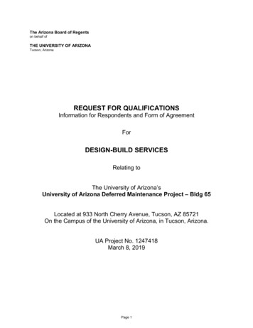
SuperCam SuperCam is a 64 pixel heterodyne receiver usedfor radio astronomyObserves at 350 GHz 857um wavelength 64 pixel array at this frequency is largest ever built This fall will be installed on the Submillimeter Telescope(SMT) on Mount Graham near Safford, AZ You created this PDF from an application that is not licensed to print to novaPDF printer (http://www.novapdf.com)
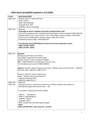
SuperCam Relay Mirror Array 7 mirror optical arraywas designed torelay sky beam fromSMT to SuperCam All 7 mirrors werefabricated at low cost 5 flat mirror and 2with curvatureYou created this PDF from an application that is not licensed to print to novaPDF printer (http://www.novapdf.com)
SuperCam Relay Mirror Array Questions arose about surfacefigure of mirrorsYou created this PDF from an application that is not licensed to print to novaPDF printer (http://www.novapdf.com)
Hardware and Software Hardware Utilized 8’ Quantum FARO Arm Software UtilizedSpatial Analyzer MATLAB SolidWorks ZEMAX You created this PDF from an application that is not licensed to print to novaPDF printer (http://www.novapdf.com)
VERIFYING SURFACE FIGUREOF OPTICS WITH FARO ARMYou created this PDF from an application that is not licensed to print to novaPDF printer (http://www.novapdf.com)
Surface Figure Accuracy:The Challenge The fabrication of optical componentsMachine shops can be challenged by complex opticalsurfaces Polishing surfaces can have an undesirable effect onsurface figure Verifying surface figure of optical componentsHow accurately was optical surface made? How does this surface affect optical performance ofsystem? You created this PDF from an application that is not licensed to print to novaPDF printer (http://www.novapdf.com)
Surface Figure Accuracy:The Solution FARO Arm and Spatial Analyzer were used to verifythe surface figure on an optical surface Measured surface was then entered into ZEMAX(optical design software) to determine resultingoptical performanceYou created this PDF from an application that is not licensed to print to novaPDF printer (http://www.novapdf.com)
Measuring an Optical Surface Mount mirror in stable position Measure surface of mirror withthe arm. Export datasetYou created this PDF from an application that is not licensed to print to novaPDF printer (http://www.novapdf.com)
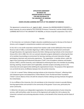
Generating a Theoretical Surface Theoretical CAD surface created in SolidWorks Conic equation ofoptical surfaceused to modelsurface:c – radius of curvaturek – conic constantr – radial coordinateYou created this PDF from an application that is not licensed to print to novaPDF printer (http://www.novapdf.com)
Generating a Theoretical Surface Theoretical surface isthen rotated so center ofmirror is at the originand its surface normal isvertical Mirror is then cut tocorrect sizeYou created this PDF from an application that is not licensed to print to novaPDF printer (http://www.novapdf.com)
Preparing Measured Dataset Measured data translated to mimic theoretical CADsurface Center of mirror at origin (0,0,0)Using MATLAB, dataset interpolated and proberadius offset is accounted forYou created this PDF from an application that is not licensed to print to novaPDF printer (http://www.novapdf.com)
Preparing Measured Dataset New dataset iscreated andoutput fromMATLABYou created this PDF from an application that is not licensed to print to novaPDF printer (http://www.novapdf.com)MATLAB’s surfacenormal function isused
Optimizing Surface Figure to CAD CAD model and MATLAB’s probe offset data isimported into Spatial AnalyzerBest-Fit Transformation used to optimize point groupto CAD surfaceYou created this PDF from an application that is not licensed to print to novaPDF printer (http://www.novapdf.com)
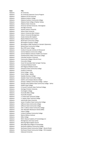
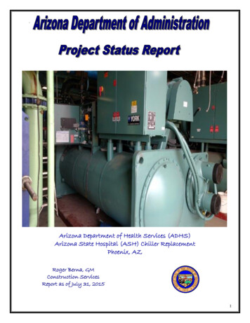
Resulting Surface Figure Error Plots of error between measured and theoretical surfacegeneratedYou created this PDF from an application that is not licensed to print to novaPDF printer (http://www.novapdf.com)
Resulting Surface Figure Error Average error from best-ft transformation:M4 - 21.1um / point M7 – 26.5um / point (shown in previous slide) These errors represent fabrication error in mirrors Conclusion: Neither mirror was fabricated perfectly Need to import measured surfaces into ZEMAX to determineoptical performanceYou created this PDF from an application that is not licensed to print to novaPDF printer (http://www.novapdf.com)
Zernike Polynomials Zernike polynomials are set of equations used torepresent a curved surfaceCan be used to enter a surface into ZEMAXYou created this PDF from an application that is not licensed to print to novaPDF printer (http://www.novapdf.com)
Generating and Using ZernikePolynomials Coefficients of Zernike polynomials generated usingopen source MATLAB scriptYou created this PDF from an application that is not licensed to print to novaPDF printer (http://www.novapdf.com)
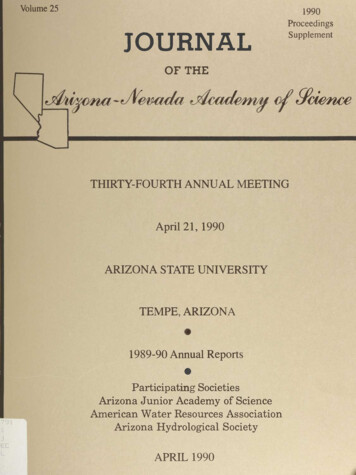
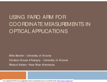
Resulting Optical System Performance Zernike coefficientsentered on top ofoptical surfaces inZEMAX Neither curved surface(M4, M7) were found tobe ideal Resulting wavefronterror was λ/20 Optical performanceslightly degraded butoverall performanceacceptableRay trace of systemYou created this PDF from an application that is not licensed to print to novaPDF printer (http://www.novapdf.com)
ALIGNING MIRRORS WITHFARO ARM AND SAYou created this PDF from an application that is not licensed to print to novaPDF printer (http://www.novapdf.com)
Mirror Array Alignment:The Challenge Using CMM to align mirror array Optical surface difficult to use as mechanicalalignment referenceTough to constrain location of probe Erroneous surface makes poor reference surface You created this PDF from an application that is not licensed to print to novaPDF printer (http://www.novapdf.com)
Mirror Array Alignment:The Solution FARO Arm was used to align SuperCam mirrorarray Range of motion is ideal for 3D coordinate measuringproblemMechanical fiducials used to couple optical surfaceto mechanical reference Cone shape constrains probeYou created this PDF from an application that is not licensed to print to novaPDF printer (http://www.novapdf.com)
Creating Mechanical References Conical reference fiducials machined into mirrorsFARO Arm measures coordinates of referencefiducials and optical surfaceYou created this PDF from an application that is not licensed to print to novaPDF printer (http://www.novapdf.com)
Optimizing Surface Figure to CAD Identical best-fit transformation as done in “Verifyingoptical surface” procedure Measured fiducial references are transformed along withoptimized surface dataResult is measured reference coordinates coupled totheoretical surfaceYou created this PDF from an application that is not licensed to print to novaPDF printer (http://www.novapdf.com)
Modeling Reference Fiducials into CAD Cones are created from reference fiducial points Bottom of cone represents the center of the FARO probe CAD mirror nowmatches realityYou created this PDF from an application that is not licensed to print to novaPDF printer (http://www.novapdf.com)
Updating CAD Assembly and Importinginto SA Modeled mirrors are mated into CAD assembly ofmirror arrayMirror array exported from SolidWorks andimported into SASolidWorksSpatial AnalyzerYou created this PDF from an application that is not licensed to print to novaPDF printer (http://www.novapdf.com)
Mirror Alignment using SA Reference fiducials ofM7 are measured andmated tocorresponding fiducialsin CAD modelYou created this PDF from an application that is not licensed to print to novaPDF printer (http://www.novapdf.com)
Mirror Alignment using SA FARO Arm is correctly located in relation to M7You created this PDF from an application that is not licensed to print to novaPDF printer (http://www.novapdf.com)
rcn15Mirror Alignment using SA Fiducials on each remaining mirror are measuredCoordinates are compared to theory / CAD in SA Mirrors are adjusted based on error between theory / CADand measured point Results to dateEarly stages of alignment have been tested and appearpromising SuperCam mirrors not ready for alignment as of 7/15/11 You created this PDF from an application that is not licensed to print to novaPDF printer (http://www.novapdf.com)
Slide 33rcn15Richard Nelson, 7/20/2011You created this PDF from an application that is not licensed to print to novaPDF printer (http://www.novapdf.com)
Verifying Alignment of Array FARO Laser tracker willbe used to verifyalignment Hot / cold loads will beused to determinewhere pixels inSuperCam instrumentare alignedYou created this PDF from an application that is not licensed to print to novaPDF printer (http://www.novapdf.com)
Conclusions Verifying surface figure of optics: Aligning mirror array: FARO Arm can be used to adequately measure and qualify thesurface figure of sub-millimeter optical components.FARO Arm will likely be an adequate alignment tool for submillimeter optics.Both procedures*: Shorter wavelength optics require too high of a precision forFARO Arm’s accuracy and these procedures.You created this PDF from an application that is not licensed to print to novaPDF printer (http://www.novapdf.com)
QUESTIONSYou created this PDF from an application that is not licensed to print to novaPDF printer (http://www.novapdf.com)
SORAL, Steward Observatory, and the University of Arizona (U of A) U of A is located in Tucson, AZ World class astronomy and optical science university Steward Observatory Offers an astronomy program for graduate and undergraduate students Develops hardware and instrumentation, including some of the worlds largest telescope mirrors SORAL - Steward Observatory Radio Astronomy