Transcription
Geometry Modeling&Grid GenerationME469B/2/GI1
Geometry Modeling & Grid Generation Geometry definition (simple shapes, CAD import) Grid generation algorithms GAMBIT Grid quality and improvement AutomationAcknowledgements:Fluent Inc. Gambit User ManualS. Owen: Introduction to unstructured mesh generationME469B/2/GI2
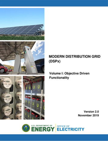
Simulation Process231. Build CAD Model2. Mesh4. Computational AnalysisME469B/2/GI3. Apply BoundaryConditions5. Visualization3
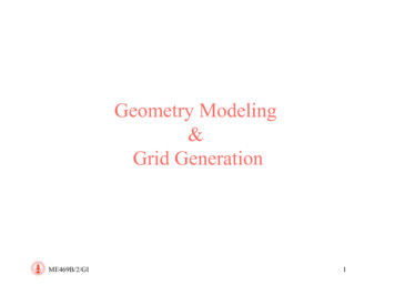
Adaptive Simulation ProcessUsersupplies meshingparameters231. Build CAD M odel2. M esh3. Apply Boundary ConditionsAdaptivity LoopError?Error εAnalysis Codesupplies meshingparameters6. Remesh/Refine/Improve4. Computational Analysis5. Error EstimationError εME469B/2/GI7. Visualization4
GeometryMesh GenerationGeometry EngineME469B/2/GI5
Grid generation package: GAMBITFile FormatSpecialGeometry Grid BC ToolsGeometryToolsVolumeToolsVisualizationTools6
GAMBITgambit -id namefile Interactive execution with GUIgambit -inp journalfile Batch execution without GUIBatch and GUI execution are EXACTLY equivalent!Geometry & Grid are saved in a database file (*.dbs)The mesh is saved into a solver-dependent file (*.msh)At the end of each session Gambit automatically saves a journal file (*.jou)ME469B/2/GI7
Geometryvertices:x,y,z locationME469B/2/GI8
Geometryvertices:x,y,z locationME469B/2/GIcurves: boundedby two vertices9
Geometryvertices:x,y,z locationME469B/2/GIcurves: boundedby two verticessurfaces: closedset of curves10
Geometryvertices:x,y,z locationME469B/2/GIcurves: boundedby two verticesvolumes: closedset of surfacessurfaces: closedset of curves11
Geometryvertices:x,y,z locationME469B/2/GIcurves: boundedby two verticesvolumes: closedset of surfacessurfaces: closedset of curvesgroup: collectionof volumes12
GeometrySurface 11Volume 1Manifold Geometry:Each volume maintainsits own set of uniquesurfacesVolume 2Volume 2Surface 7Surface 8Surface 9Surface 10Surface 11Surface 6Surface 7Volume 1Surface 1ME469B/2/GISurface 2Surface 3Surface 4Surface 513
GeometryVolume 1Non-ManifoldGeometry: Volumesshare matching surfacesVolume 2Volume 2Surface 7Surface 8Surface 9Surface 10Volume 1Surface 1ME469B/2/GISurface 2Surface 3Surface 4Surface 5Surface 6Surface 714
Geometry & TopologyGeometry types in Gambit Real Geometry: entities characterized by a direct definition of their geometryexample: a vertex defined by its coordinates (0,0,0) Virtual Geometry: entities characterized ONLY by an indirect definition, i.e. areference to another entity.example: a vertex is defined as the mid-point of an edge Faceted Geometry : entities characterized ONLY by an indirect definition withrespect to an underlying gridexample: a vertex is defined as the corner of a mesh elementME469B/2/GI15
Geometrical types - Topology Vertex Edge (2 or more vertices) Face (3 or more edges) Volume (4 or more faces)Bottom-up approach: generate low dimensional entities andbuild on top of them higher dimensional entitiesTop-bottom approach: generate upper dimensional entities and useboolean operation to define the other entitiesME469B/2/GI16
Vertex: Input Coordinates Edge: Line segment (connect 2 vertices) Circular arc Quadratic functions NURBS: Non-Uniform Rational B-Splines (connect N vertices)Topologically any edge is ALWAYS a connection between 2 vertices(additional vertices used to build the geometry are NOT part of the edge)ME469B/2/GI17
Edge by NURBSNon-Uniform Rational B-SplinesGeneralization of Bezier interpolants: each point is computed as the weightedsum of all the knot pointsNURBS can use various blending/control functions (for the weights)Can achieve high degree of URBS.htmME469B/2/GI18
Face: Rectangular Circular Sweep (translation or rotation of an edge) Wireframe (connecting 3 or more edges)ME469B/2/GI19
Volume: Cuboid Sphere Cone Pyramids Sweep (translation or rotation of a face) Wireframe (connecting 3 or more faces)ME469B/2/GI20
Manipulate Geometry - Boolean Operations:Volume 1 Unite Substract IntersectVolume 2it generates theintersection edgeME469B/2/GI21
Manipulate Geometry - Blendsmooth sharp edgesME469B/2/GI22
Create Entities - FacesME469B/2/GI23
Create Entities - FacesSome entities generated using “primitives” have fewer lower topological entitiesExample:Cube volume: 6 faces, 12 edges, 8 verticesCylinder volume: 3 faces, 2 edges, 2 verticesME469B/2/GI24
Manipulate Geometry – Create EntitiesCreate a vertex on a faceParametric representationof the faceME469B/2/GI25
Manipulate Geometry – Create EntitiesCreate two edges by splitting an edgeParametric representationof the edgeME469B/2/GI26
Manipulate Geometry – ScalingGeometrical scaling of a volume (isotropic)Scaling is based on a Reference PointDefault (0,0,0) - origin of the original Cartesian coordinate systemIt is possible to introduce additional coordinate systemsME469B/2/GI27
Manipulate Geometry – AlignModify the geometry of an entity with referenceto another oneME469B/2/GI28
Connect GeometryBuilding upper topological entities from the lower onesrequires that they are properly onsME469B/2/GI29
Import Geometries Realistic geometries are TOO complicated to be generatedfrom “simple” shapes Engineering design is based on CAD systemsTranslation between CAD and CFD system is a major bottleneck Gambit is based on ACIS geometrical libraries ACIS (Andy, Charles & Ian’s System) is the most widely used 3Dmodeling software technology (http://www.spatial.com) It can also import: STEP (STandard for Exchange of Product model data; ISO standard) IGES (Initial Graphics Exchange Specification; ANSI standard) STL (STereo Lithography; Rapid Prototyping Standard) .ME469B/2/GI30
Import GeometriesME469B/2/GI31
Clean-Up a CAD Model Eliminate components not exposed to the flow Eliminate duplicated entities Eliminate small details Water-proofing the surfaces Rebuild geometrical connectivity between partsME469B/2/GI32
Example: Helicopter RotorThe rotor-shaft connectionis VERY complicatedME469B/2/GI33
Geometrical entitiesThe geometry consists of 10 components3 blades, 1 shaft support, 6 connectorsME469B/2/GI34
Example: Import IGES ModelIGES export is available from everyCAD systemIGES models are a collection of“untrimmed” edges and facesImported geometry consists of:0 volumes 250 faces 1100 edges 1000 verticesME469B/2/GI35
Example: Import STEP ModelSTEP export is available from manyCAD systemSTEP models are a collection of partsor componentsImported geometry consists of:10 volumes 190 faces 450 edges 300 verticesME469B/2/GI36
Components r aerodynamic analysis the details of the rotor-shaftconnection are not important. The geometry of theblades MUST be preservedME469B/2/GI37
Geometry simplificationConnectors eliminatedSupport generated as a“simple” cylinder withblended sideME469B/2/GI38
Geometry simplificationBlade edge cleaned andsealedBlade-support connectoris a “simple” cuboidME469B/2/GI39
Clean GeometryThis example is available on the class Web siteME469B/2/GI40
Virtual GeometryGAMBIT operates on two different type of entitiesREAL: with corresponding geometrical and topological characteristicsVIRTUAL: defined only with reference to REAL or other VIRTUAL entitiesREAL entities are what we used and described so far;VIRTUAL are used to SIMPLIFY, CLEAN UP, DECOMPOSE real entitiesNote that some geometry tools cannot be applied to virtual entities(boolean operation, volume blending, creation of volumes by sweeping faces, etc.)ME469B/2/GI41
Virtual GeometrySuperset: Entity that references two or more real entitiesInterpolant: Entity represents an average/interpolant ot various real entitiesParasite: Entity defined completely from a real entityThe virtual geometry is typically constructed using a host entityReal entities can be transformed in virtual but NOT ALWAYS viceversaME469B/2/GI42
Virtual Geometry Clean-UpExample of edge connecting operation: virtual interpolantREALME469B/2/GIVIRTUAL43
Clean-Up CracksA "crack" is defined as a geometry consisting of an edge pairthat meets the following criteria.・Each edge in the pair serves as a boundary edge for a separate face.・The edges share common endpoint vertices at one or both ends.・The edges are separated along their lengths by a small gap.ME469B/2/GI44
Clean-Up Hard EdgesHard edges (dangling edges) are those that are included in the list ofedges that define a face but which do not constitute necessary parts ofthe closed edge loop that circumscribes the face.Such edges often result from face-split operations in which the splittool face only partially intersects the target face.ME469B/2/GI45
Grid Generation Geometry definition (simple shapes, CAD import) Grid generation algorithms GAMBIT Grid quality and improvement AutomationME469B/2/GI46
Grid generation techniques Structured grids Ordered set of (locally orthogonal) lines Several Techniques can be used to Map a computational domain intoa physical domain: Transfinite Interpolation, Morphing, PDE Based, etc. The grid lines are curved to fit the shape of the boundaries Unstructured grids Unorganized collection of polygons (polyhedron) Three main techniques are available to generate automatically triangles(tetrahedra): Delaunay triangulation, Advancing front, OCTREE Paving for automatic generation of quads in 2DME469B/2/GI47
Grid generation techniquesFrom S. Owen, 2005ME469B/2/GI48
Grid generation techniquesGambit is a “commercial” grid generator and includes only few (relativelystandard) algorithms. New methods are slow to gain robustness andgenerality and therefore are not directly availableCubit is a “research” grid generator and the latest approaches are typicallyincluded (several of them have been actually invented by the Cubit team)http://cubit.sandia.gov/ME469B/2/GI49
Grid generation techniquesFrom S. Owen, 2005ME469B/2/GI50
Structured Grids: MappingTransfinite InterpolationSide BSide A1Physical DomainME469B/2/GISide Bkjj NJ 1k NKSide CSide A1 Side A2Side DeCSide A2S idj 1 NJk 1Side DComputational Domain51
Structured Grids: Sub-mappingRegions are automatically subdivided in “mappable areas”Number of grid elementshave to be chosen consistentlyThe grid type is controlledby a vertex attributeME469B/2/GI52
Vertex-face typeUser can specify the behavior of the grid at a certain nodeME469B/2/GI53
Unstructured Grids: Triangulations Delaunay Empty circle principle: any node must not be contained within thecircumcircle (circle passing through the vertices of a triangle) on anytriangle within the mesh Automatic triangulation of random set of nodes Nodes are inserted locally in a triangulation and triangles are redefinedlocally to satisfy the Delaunay criterion (available mathematical tools) Inherent grid quality Elegant mathematical basis- Boundary integrityME469B/2/GI54
DelaunaycircumcircleME469B/2/GIEmpty Circle (Sphere) Property:No other vertex is contained within the circumcircle(circumsphere) of any triangle (tetrahedron)55
DelaunayME469B/2/GIDelaunay Triangulation:Obeys empty-circle (sphere) property56
DelaunayNon-Delaunay TriangulationME469B/2/GI57
DelaunayGiven a DelaunayTriangulation of n nodes,How do I insert node n 1 ?XLawson Algorithm Locate triangle containing X Subdivide triangle Recursively check adjoiningtriangles to ensure emptycircle property. Swapdiagonal if needed (Lawson,77)ME469B/2/GI58
DelaunayXLawson Algorithm Locate triangle containing X Subdivide triangle Recursively check adjoiningtriangles to ensure emptycircle property. Swapdiagonal if needed (Lawson,77)ME469B/2/GI59
DelaunayrXdcBowyer-Watson Algorithm Locate triangle that containsthe point Search for all triangleswhose circumcircle containthe point (d r) Delete the triangles (creatinga void in the mesh) Form new triangles from thenew point and the voidboundary (Watson,81)Given a DelaunayTriangulation of n nodes,How do I insert node n 1 ?ME469B/2/GI60
DelaunayXBowyer-Watson Algorithm Locate triangle that containsthe point Search for all triangleswhose circumcircle containthe point (d r) Delete the triangles (creatinga void in the mesh) Form new triangles from thenew point and the voidboundary (Watson,81)Given a DelaunayTriangulation of n nodes,How do I insert node n 1 ?ME469B/2/GI61
Unstructured Grids: Triangulations Advancing front Triangles are built inward from the boundary surfaces The last layer of elements constitutes the active front An optimal location for a new nodes is generated for each segment onthe front; the new node is generated by checking all existing nodes andthis new optimal location Intersection checks are required to avoid front overlap Surface grid preserved Specialized layers near surfaces- Computationally complex- Low qualityME469B/2/GI62
Advancing FrontCAB Begin with boundary mesh - define as initial front For each edge (face) on front, locate ideal node C based on front ABME469B/2/GI63
Advancing FrontrCADB Determine if any other nodes on current front are within searchradius r of ideal location C (Choose D instead of C)ME469B/2/GI64
Advancing FrontD Book-Keeping: New front edges added and deleted from front astriangles are formed Continue until no front edges remain on frontME469B/2/GI65
Advancing Front Book-Keeping: New front edges added and deleted from front astriangles are formed Continue until no front edges remain on frontME469B/2/GI66
Advancing Front Book-Keeping: New front edges added and deleted from front astriangles are formed Continue until no front edges remain on frontME469B/2/GI67
Advancing Front Book-Keeping: Ne
ME469B/2/GI 2 Geometry Modeling & Grid Generation Geometry definition (simple shapes, CAD import) Grid generation algorithms GAMBIT Grid quality and improvement