Transcription
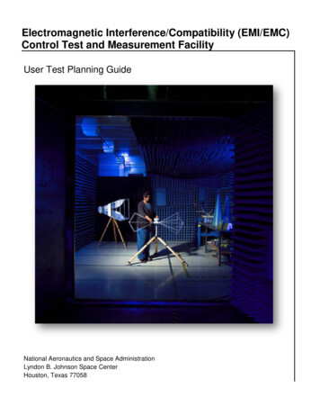
Electromagnetic Interference/Compatibility (EMI/EMC)Control Test and Measurement FacilityUser Test Planning GuideNational Aeronautics and Space AdministrationLyndon B. Johnson Space CenterHouston, Texas 77058
Table of Contents1.0Electromagnetic Interference/Compatibility Test Facility .32.0Facility Layout .43.0Safety and Health .64.0Test Process Flow .64.1.Proprietary Information .74.2Test Initiation Phase .84.2.1Test Request . 84.2.2Schedule and Cost Estimate . 94.3Test Preparation Phase .94.3.1Test Requirements . 104.3.2Test Article Documentation . 104.3.3Test Plan . 114.3.4Test Schedule . 114.3.5Test Article Delivery . 114.3.6Test Readiness Review . 114.4Test Execution Phase .124.4.1Test Authority . 124.4.2Test Deviations . 124.5Test Closeout Phase .134.5.1Customer Feedback . 135.0Facility Access .146.0Roles and Responsibilities .15Acronyms .17Appendices .18Appendix AFacility Interfaces.19Appendix BTest Request Worksheet .23Appendix CFacility Specifications .28Appendix DFacility Equipment .29Appendix ESample Test Configurations .322
1.0 Electromagnetic Interference/Compatibility Test FacilityThe Electromagnetic Interference/Electromagnetic Compatibility (EMI/EMC) Control Test andMeasurement Facility supports engineering development and EMI/EMC measurements andprovides EMI/EMC evaluation and certification testing of crew, flight, and ground supportequipment including, but not limited to, Communication, Instrumentation, Biomedical, Guidanceand Navigation, Computation, and Robotics.Services Provided Testing - developmental, engineeringsupport, performance and precertificationevaluation, and certification testingConducted and radiated emissions andsusceptibility testing (e.g., MIL-STD-461,all revisions; RTCA/DO-160, sections 16through 21)Lightning indirect effects and ElectrostaticDischarge (ESD) assessment(e.g., RTCA/DO-160, sections 22 and 25)Cable transfer impedance and equipmentshielding effectiveness assessmentEMC design consultationDetailed test planning support and testdata collection/reportingCapabilitiesShielded room enclosuresMeet military standard MIL-STD-285Synthesized signal generatorsCapable of covering a frequency range of 10 Hz to 26 GHzRadio frequency (RF) power amplifiersProvide up to 500 W of output power in the frequency range of 10 kHz to18 GHzLightning transient generator andsupport probesProvide test waveforms 1, 3A, 3B, 4, and 5A for lightning indirect effectstesting up to Level 3ESD test equipmentProvides standard ESD test waveforms up to a 30 kV peak pulse voltageComplete line of general purposeancillary test equipmentPower supplies, oscilloscopes, power meters, and voltmetersHigh-fidelity EMC modeling softwareGeneral purpose three-dimensional electromagnetic modelingPoint of ContactLab Manager, Richard DeppischJohnson Space Center2101 NASA Parkway, Houston, TX 77058(281) 483-0475richard.m.deppisch@nasa.gov3
2.0 Facility LayoutThe facility has two shielded enclosures, or chambers, as shown in the accompanying figures.The primary chamber is designed to accommodate larger pieces of equipment. The wall,ceiling, and floor are constructed of panels of 24-gauge galvanized steel sheets laminated toboth sides of a ¾-inch structural core. The floors are covered with tile and are designed tohandle a loading capacity of 1,000 lb. per square foot. Each chamber is equipped with a 9′ W x3′ D ground plane bench, covered with a copper sheet that is electrically bonded to the adjacentwall. The test benches stand 30 inches above the floor.KEY1000A3’x5’tableTest Rm.18’X23’X10’Absorber 0BPC&PrinterControl Rm.10’X12’X10’23’10RMAIP BIP A1000BASupport Rm.10’X11’X10’CIP C57’2’6”x5’tableTest benchIP DDoorsA - Sgl., 3’6” w X 7’6” h, 4.5” lipB – Dbl., 8’ w X 10’ h, 3.5” lipC – Sgl., 3’6” w X 7’6” h, 4.5” lipHB – 13’ w X 20’ hIP A, IP B & IP C – 2” IDIP D – 4” ID2’6”x5’table3’6” 3’4”To 102028’OH DoorLadder upto 2P2100010RW9’4”35’ 8”NOTE: The walls and ceiling of the test room are treated with ferrite tiles and absorber material out to the dotted line and acrossthe back wall. Test Bench can be removed or another may be added as needed to accommodate hardware.Physical Layout of EMI/EMC Primary Facility in B14A/R1000 High Bay4
Large Equipment Under Test (EUT) can be accommodated in the primary chamber via the13′-wide rollup High Bay door in Johnson Space Center (JSC) Building 14A, Room 1000.Heavy EUT can be handled with a forklift or crane, operated by local riggers. EUT too large tofit on the ground plane table may be accommodated by removal of the ground plane bench.Ramps are available so that EUT can be easily moved inside over the 3.5″ chamber doorwaythreshold. Handling of fixtures, test item placement, and service connections should beresolved during pretest coordination and planning.8’4” L X 6’ W20º downward rampDKEYDoorsA - 3’6” w X 7’ h, 3” lipB – Dbl., 6 w X 7’6” h , 3” lipC – 3’6” w X 7’ h , 3” lipD – Dbl., 6 w X 7’ hIP E & IP G – 2” IDIP F – 4” IDR133D4’4”8’ W �4’6”IP GA10’Test Rm.16’X10’X8’6”Control Rm.8’X10’X8’6”PC& PrinterEMI Rcvr.3’10”CBWork BenchIP E4’ X 8’Test BenchStairway2’ X 2’EUTTableEUT GSESupport Rm.11’6”X10’X8’6”IP F3’ X 3’Table35’6”Physical Layout of EMI/EMC Secondary Chamber in B14/R133D* See Appendix A for facility interface information and Appendix E for sample test configurations.5
3.0 Safety and HealthSafety is an integral part of the culture at the National Aeronautics and Space Administration(NASA). Management, leadership, and employee involvement from all organizations are criticalto the success of NASA’s safety program. In order to ensure personal safety and a safe testenvironment throughout the process, the requester shall furnish the facility with the informationnecessary to perform a hazard assessment of the test article. Additionally, while visiting JSC,the requester shall follow all facility-specific safety and health requirements. A facility safetybriefing shall be provided to all personnel prior to the start of the test. The safety briefing willinclude a review of the laboratory safety rules, potential hazards, and emergency procedures.4.0 Test Process FlowThe flowchart presented below outlines the basic roadmap and significant milestones betweenthe initial test request and delivery of test data. The flow is separated between Test Requesteractions and Facility actions, highlighting interactions and inputs between the Test Requesterand the facility Test Director.6
The test schedule is highly dependent on the complexity of the test, facility availability, andsequence of runs. For time-critical testing, it may be possible to accelerate the schedule, givenconstraints associated with previous customer commitments. A detailed schedule shall bedeveloped as part of the test planning process following a review of the test objectives andrequirements. Typical major milestones are presented below:Note: The schedule is subject to the complexity of test requirements.4.1. Proprietary InformationThe EMI/EMC Test Facility provides for protection of proprietary information and hardwarethroughout the test process. The Test Requester shall clearly mark all export controlled orproprietary hardware items and data provided with a notice of restriction on disclosure or usage.The Test Director shall safeguard export controlled or proprietary items from unauthorized useand disclosure and ensure that test articles remain secure within the facility and are properlysequestered. Hardware items shall be returned to the Test Requester or disposed of inaccordance with the Test Requester’s instructions at the completion of the test activity.7
4.2Test Initiation PhaseThe test initiation phase establishes the relationship between the Test Requester and the TestDirector. The Test Requester shall provide a test request to the Test Director. The test requestwill be used to determine test feasibility and to develop an estimated cost and a preliminary testschedule. An initial requirements review meeting may be necessary in order to discuss thecharacteristics of the test article, the test approach, or any special considerations for the test.An onsite tour of the facility is highly recommended for familiarization and to provide anopportunity for an exchange of technical information.Inputs:Test Requester provides test request, identifies Test Article ExpertActivities:Facility Test Director reviews test request to determine test feasibilityOutputs:Facility delivers preliminary test plan, estimated cost and schedule to TestRequester4.2.1 Test RequestThe test request outlines the EUT requirements, test objectives, test article description, andpreferred schedule. A Test Request Worksheet is provided in Appendix B. This worksheetaddresses the basic requirements for testing in the EMI/EMC Test Facility. It is suggested thatthe Test Requester complete this worksheet to facilitate the development of a preliminary testplan. At a minimum, the test request should include the following information:Test Requirements and ObjectivesA brief description of the test requirements including, but not limited to, the following: Applicable EMI/EMC requirements/limits/specification (e.g., customer specification,MIL-STD-461, DO-160) Desired test environment and modes of operation Proposed test approach Test data requirements8
Test Article DescriptionA brief description of the test article including, but not limited to, the following: Size/dimensions (provide drawings, sketches, photos) Weight Test article interface (electrical, mechanical, fluids, gases, pressure, temperature,other) Special considerations [hazards, cleanliness, compatibility, Material Safety DataSheets (MSDS)] Handling, storage, and security requirementsScheduleIdentify the desired start date and the required date for delivery of the data/test report.4.2.2 Schedule and Cost EstimateA preliminary cost and schedule estimate, including major milestones, will be delivered followingreview of the Test Request Worksheet. Additional details and refinement of the cost andschedule estimate will be worked out with the Test Requester as test planning proceeds, with afinal version to be agreed upon prior to the Test Readiness Review (TRR).4.3Test Preparation PhaseThe detailed test plan and test schedule are finalized during the test preparation phase. TheTest Requester shall provide detailed test requirements and test article documentation to theTest Director. A TRR will be held following approval of the test plan.Inputs:Test Requester provides test requirements and objectives, and test articledocumentationActivities:Facility and Test Requester develop test planFacility begins assembly of facility-unique interface/support structure(s) (if needed)Test Requester ships/transports test article and associated support/peripheralequipment to JSCOutputs:Test Requester approves test plan, schedule, and final cost estimateFacility hosts TRR9
4.3.1 Test RequirementsA complete understanding of test requirements and facility capabi
(e.g., RTCA/DO-160, sections 22 and 25) Cable transfer impedance and equipment shielding effectiveness assessment EMC design consultation Detailed test planning support and test data collection/reporting. Capabilities . Shielded room enclosures . Meet military standard MIL-STD-285 . Synthesized signal generators ; Capable of covering a frequency range of 10 Hz to 26 GHz . Radio .