Transcription
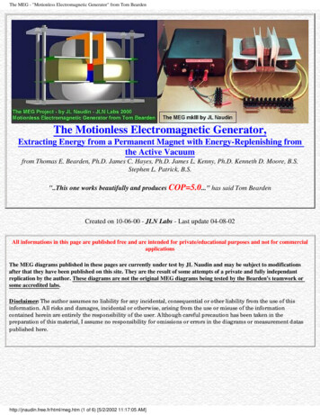
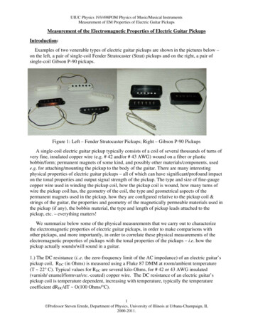
UIUC Physics 193/498POM Physics of Music/Musical InstrumentsMeasurement of EM Properties of Electric Guitar PickupsMeasurement of the Electromagnetic Properties of Electric Guitar PickupsIntroduction:Examples of two venerable types of electric guitar pickups are shown in the pictures below –on the left, a pair of single-coil Fender Stratocaster (Strat) pickups and on the right, a pair ofsingle-coil Gibson P-90 pickups.Figure 1: Left – Fender Stratocaster Pickups; Right – Gibson P-90 PickupsA single-coil electric guitar pickup typically consists of a coil of several thousands of turns ofvery fine, insulated copper wire (e.g. # 42 and/or # 43 AWG) wound on a fiber or plasticbobbin/form; permanent magnets of some kind, and possibly other materials/components, usede.g. for attaching/mounting the pickup to the body of the guitar. There are many interestingphysical properties of electric guitar pickups – all of which can have significant/profound impacton the tonal properties and output signal strength of the pickup. The type and size of fine-gaugecopper wire used in winding the pickup coil, how the pickup coil is wound, how many turns ofwire the pickup coil has, the geometry of the coil, the type and geometrical aspects of thepermanent magnets used in the pickup, how they are configured relative to the pickup coil &strings of the guitar, the properties and geometry of the magnetically permeable materials used inthe pickup (if any), the bobbin material, the type and length of pickup leads attached to thepickup, etc. – everything matters!We summarize below some of the physical measurements that we carry out to characterizethe electromagnetic properties of electric guitar pickups, in order to make comparisons withother pickups, and more importantly, in order to correlate these physical measurements of theelectromagnetic properties of pickups with the tonal properties of the pickups – i.e. how thepickup actually sounds/will sound in a guitar.1.) The DC resistance (i.e. the zero-frequency limit of the AC impedance) of an electric guitar’spickup coil, RDC (in Ohms) is measured using a Fluke 87 DMM at room/ambient temperature(T 22 C). Typical values for RDC are several kilo-Ohms, for # 42 or 43 AWG insulated(varnish/ enamel/formvar/etc.-coated) copper wire. The DC resistance of an electric guitar’spickup coil is temperature dependent, increasing with temperature, typically the temperaturecoefficient dRDC/dT O(100 Ohms/ C).1 Professor Steven Errede, Department of Physics, University of Illinois at Urbana-Champaign, IL2000-2011.
UIUC Physics 193/498POM Physics of Music/Musical InstrumentsMeasurement of EM Properties of Electric Guitar Pickups2.) The magnetic polarity (North or South) of pickup poles is measured/defined using a simplemagnetic compass, at the top of the pickup – e.g. if the red (white) compass needle points/isattracted to the pickup pole at the top of the pickup, then this pole has south (north) polarity,respectively. {n.b. Recall that the Earth’s north geo-magnetic pole is actually a south magneticpole!}. The magnetic polarity of the pickup poles can also be determined using the Gauss meterfrom sign (polarity) information of the readout of the Gauss meter – see below 3.) The magnetic polarity and magnetic field strength of an electric guitar pickup’s poles, Bpole(in Gauss) is measured using a Walker Scientific MG-50 Gauss meter in conjunction with atransverse Hall probe placed in direct contact with each pole of the pickup, at the top of thepickup. If the reading of the Gauss meter is positive (negative), then the pole has north (south)magnetic polarity, respectively {n.b agrees/checks with the above compass needle test}.The *maximum* magnetic field reading per pole is recorded, rounded off to the nearest 5 Gauss(the intrinsic reproducibility/accuracy of these measurements). Typical values for Bpole rangefrom 300-400 G for 50% charged AlNiCo-III (i.e 600-800 G for fully-charged AlNiCoIII), 800-900 G for fully-charged AlNiCo-II, 900-1100 G for fully-charged AlNiCo-V, and 800-1100 G for ceramic magnets, depending on their composition. The B-field from an electricguitar pickup poles decreases rapidly as one moves away from them, the exact dependence israther complicated due to the finite size of the poles (diameter & height) as well as the presenceof magnetically permeable and other permanent magnets in proximity to the magnet poleundergoing measurement, however very crudely, the B-field decreases approximately as 1/r3(i.e. that of a pure, point magnetic dipole).4.) The winding direction of the coil(s) of an electric guitar pickup is defined from visualinspection, using the convention of CW/CCW winding, from start to finish of the coil wind,viewed from the top of pickup.5.) The “pull-off” polarity ( output voltage sense) of the pickup is measured using e.g. a smallscrewdriver, with the pickup under test connected either to a DMM on 300 mVdc scale or to anoscilloscope, with the “hot” (ground) lead of the pickup connected to the ( ) terminal of theDMM/oscilloscope respectively. The blade of the screwdriver is slowly (and gently!) broughtinto direct contact with a pickup pole of the pickup at the top of the pickup, and then abruptlypulled vertically upward, away from the pickup, while simultaneously observing the polarity ofthe time-dependent voltage deflection V(t) either on the DMM or oscilloscope. For a is positive(negative) voltage deflection V(t) as the screwdriver blade is pulled of the pickup pole, the“pull-off” polarity of the pickup is positive (negative), respectively.6.) The (lumped) inductance, L(f) and its associated dissipation, DL(f) of an electric guitar pickupare measured using a Hewlett-Packard 4262A LCR meter at three different frequencies: f 120Hz, 1 KHz and 10 KHz. The HP LCR meter analyzes inductance L(f) and dissipation DL(f) as a“2-component black-box” – i.e. either as a simple lumped series L-R network or simple lumpedparallel L-R network. The former (latter) is appropriate/physically meaningful for low (high)frequencies for electric guitar pickups when the reactance of the pickup χ(f), at the frequency,f 120 Hz, 1KHz or 10KHz, is χ(f) RDC (χ(f) RDC) for series L-R (parallel L-R),respectively. Note that the dissipation, DL(f) is related to the quality factor, QL(f) by QL(f) 1/DL(f) or DL(f) 1/QL(f). Physically, for ideal inductors (or capacitors), their impedances Z arepurely imaginary – i.e. purely reactive. However for real inductors (or capacitors), any real2 Professor Steven Errede, Department of Physics, University of Illinois at Urbana-Champaign, IL2000-2011.
UIUC Physics 193/498POM Physics of Music/Musical InstrumentsMeasurement of EM Properties of Electric Guitar Pickups(i.e. in-phase) component of impedance can only be due to dissipation of some kind – e.g. aresistance. The mathematical formula for dissipation, DL(f) is defined as the ratio of the real(in-phase) component of the complex impedance to the reactive (90o out-of-phase) component ofthe complex impedance, i.e. DL(f) Re(Z(f))/Im(Z(f)) of the pickup at each frequency, soanalyzed by this device. Thus, dissipation is a dimensionless quantity. We call the real part of thecomplex impedance for an inductor (or capacitor), the AC resistance RD(f).For a series L-R network: RDs(f) χLs(f) DLs(f) 2πf Ls(f) DLs(f).For a parallel L-R network: RDp(f) χLp(f)/DLp(f) 2πf Lp(f)/DLp(f).If the electric guitar’s pickup resonant frequency is 1 KHz fres 10 KHz, where the pickupimpedance, Z(f fres) is a maximum in this frequency range, then no measurement of theinductance, L(f) at f 10 KHz is possible with the HP 4262A, due to the measurement techniqueused by the HP 4262A (one form of AC bridge). However, one can instead measure thecapacitance, C(f) of the pickup at f 10 KHz with the HP 4262A, analyzing the electric guitarpickup as a lumped, parallel C-R circuit, because the reactance, χ(f) on the high side of theresonance of the pickup, i.e. f fres has negative slope (i.e. dχ(f)/df 0), due to the dominance ofthe pickup’s capacitance, C over the pickup’s inductance, L in this frequency region, i.e. χC(f) χL(f) when f fres (conversely, χC(f) χL(f) when f fres). Again, we can also simultaneouslyobtain a measurement of the dissipation, DC(f), which is again related to the quality factor, QC(f) 1/DC(f), or DC(f) 1/QC(f). The mathematical formula for the dissipation, DC(f) can again beused to calculate the resistive/dissipative (real/in-phase) component, RD(f) of the compleximpedance of the pickup, Z(f) at the frequency, f, so analyzed by this device.For a series C-R network: RDs(f) χCs(f) DCs(f) [1/(2πf Cs(f))] DLs(f).For a parallel C-R network: RDp(f) χCp(f)/DCp(f) [1/(2πf Cp(f))]/DLp(f).In reality, an electric guitar pickup is considerably more complicated than the simple, verycrude model of a pickup consisting of a lumped series L-R in parallel with a lumped C, becausethe actual L, R and C are distributed over the many thousands of turns of the pickup coil.Furthermore, the pickup inductance, L is not a constant, independent of frequency due tofrequency-dependence of the magnetization, M (magnetic dipole moment per unit volume) of thepermanent magnet(s) used in the pickup, how fully the magnets are charged (i.e. where thepermanent magnets reside on the B-H hysteresis curve) as well as the frequency-dependentproperties of the magnetically permeable material(s) used in the construction of the electricguitar pickup – soft iron pole pieces, booster plates, even frequency-dependent eddy currenteffects in nonmagnetic metal components associated with the pickup – booster plates, mountingbrackets, screws, etc. Thus, L L(f). In addition to these effects, even the pickup resistance atfinite frequency, R(f) differs significantly from that at zero frequency, i.e. R(f) RDC R(f 0)due to frequency-dependence of turns of wire in the coil coupling to each other and also themagnetic dissipation processes extant in the electric guitar pickup associated with the permanentmagnets and the magnetically permeable materials of the pickup, the effects of eddy currentsinduced in conducting materials used in the construction of the pickup (and/or in proximity to thepickup) and also frequency-dependent resistivity effects associated with the fine-gauge pickupwire (immersed in the magnetic field of the pickup) of the pickup coil. Nevertheless, themeasured pickup capacitance C(f 10 KHz), and corresponding DC(f 10 KHz) info obtained isuseful. We also compute RC(f) from this data.3 Professor Steven Errede, Department of Physics, University of Illinois at Urbana-Champaign, IL2000-2011.
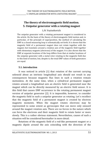
UIUC Physics 193/498POM Physics of Music/Musical InstrumentsMeasurement of EM Properties of Electric Guitar Pickups7.) The complex impedance of the pickup Z(f) and output voltage V(f) as a function of frequencyf are measured using a PC-based DAQ system that we have specifically designed to carry outthese measurements. As shown schematically in Figure 3 below, the PC controls the internalsine-wave of one of two lock-in amplifiers via GPIB. We set the sine-wave amplitude to 1.0 voltand step through the frequency from 5 Hz to 20.005 KHz in 2000 frequency steps of 10 Hz. The50 Ohm, low-impedance output of the sine wave oscillator (an constant voltage source) isconverted to a high-impedance, constant current source (in order to emulate the constantcurrent excitation of the pickup via a vibrating electric guitar string, when plucked) using a 1.5meg-ohm metal-film (low Johnson noise) resistor in series with the sine wave oscillator’s output.The "hot" lead of the electric guitar pickup is connected to the output side of the 1.5 Megohmresistor. The other lead of the pickup is connected to a 100 Ohm shunt resistor, and the other leadof this resistor is connected to the signal ground of the sine wave oscillator. We measure thecomplex voltage (real/in-phase and imaginary/90-degrees out-of-phase voltage components)across the pickup and using a Stanford Research model SRS 830 DSP-based lock-in amplifier.We do not connect pickup directly to the input of the lock-in amplifier, but first unity-gain bufferthe voltage signal from the pickup using an Analog Devices AD624AD low-noise JFETinstrumentation op-amp, which has very low output impedance and thus can very easily drive theinput of the lock-in amplifier over the entire audio frequency range (n.b. the dynamic inputimpedance of the lock-in amplifier varies significantly with frequency and filteringoptions/settling time, etc and loads down the high-impedance of the pickup, if connecteddirectly, giving very significantly biased results over the entire audio spectrum). We alsoexplicitly measure the complex current (real/in-phase and imaginary/90-degrees out-of-phasecurrent components) flowing through the pickup via the voltage developed across the 100 Ohmshunt resistor, and again use a unity-gain AD624AD low-noise JFET instrumentation op-amp tobuffer the current signal before inputting it to a second SRS-830 lock-in amplifier. The twoAD624's are housed in a shielded/grounded metal box to suppress RFI/60Hz/etc. noise pickup.Short alligator leads are used to connect the leads of the pickup to this front-end electronics. Thesine-wave signal from internal oscillator of one of the lock-in amplifiers is used as a referencesignal for the complex voltage and current measuring lock-in amplifiers.The quasi-static voltages present on the X (in-phase) and Y (90o out-of-phase) outputs of thetwo lock-in amplifiers used for measuring the complex voltages & currents in the pickup at eachfrequency are measured using four ADC’s (Analog-to-Digital-Converters).We use a National Instruments LabPC DAQ card, which has eight 12-bit gain-programmableADC's and two 12-bit DAC's (both with 5 V max. dynamic range), and 24 TTL I/O lines, todigitize the analog outputs of the SRS-830 lock-in amps at each f
“pull-off” polarity of the pickup is positive (negative), respectively. 6.) The (lumped) inductance, L(f) and its associated dissipation, D . pickup) and also frequency-dependent resistivity effects associated with the fine-gauge pickup wire (immersed in the magnetic field of the pickup) of the pickup coil. Nevertheless, the measured pickup capacitance C(f 10 KHz), and corresponding DC .