Transcription
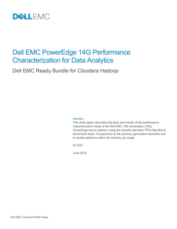
Tool CleanlinessCharacterization for ImprovingProductivity and YieldsVictor K.F. Chia, Ph.D.victor.chia@balazs.com
Agenda Introduction Tool componentsa Starting material selection and bulk characterizationa Surface cleanliness Chemical characterization Physical characterization Completed toolsa Tool cleanliness specification Particles Metals Organics Tool escalation case study ConclusionReducing ContaminationNew and used componentsPECVD chamber
Introduction Tool parts cleanliness is an invisible parameter that must be controlled toenable clean processingThe target contaminants affecting process yields are particles, metals andorganicsIn the sub-100 nm technology node even irreducible differences in thecomponents of identical tool chambers can influence yield and mean timebetween failure (MTBF)The first line of defense for a fab is to have clean tools for processing, fromacceptance trials of the new tool to after each PM. Only with clean tools cana fab maximize its yield by increasing overall equipment productivity andwafer throughput for increased profit marginThis may be accomplished with strict quality control of the supplier chain forstarting materials, machine shops, cleaning vendors and contractmanufacturing. In addition, cleanliness specifications must be in place forthe BOM.This presentation reviews cleanliness specifications for components andcompleted tools and characterization methods for verifying their cleanlinessReducing Contamination
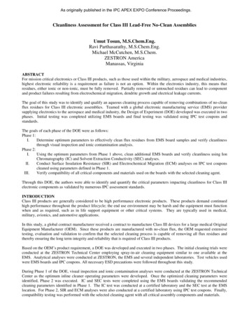
Starting MaterialsRequirements The materials used in the BOM, includinglubricants and grease, must be compatible to itsfunction and cleanliness requirements Multi-alloy parts must be cleanable Bulk material characterization is important as theroot source of wafer contamination may be fromthe bulk of the material; no amount of cleaningwill remove this contamination sourceComplex Wafer Arm AssemblyCommon materials used in build of materials ing ContaminationAlNiNi Plating Au PlatingSSTMoTiTaCu / Cu onCalrezPEEKPTFEPolyimide inumWeldedSteelAlloysBrazedBondedFlex Circuit
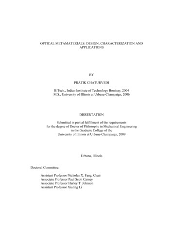
Starting Materials CharacterizationLaser ablation ICP-MSQuartz80E80E80E80ELayer 1Layer 2Layer 3Layer 4SubstrateMass tDefectMetals on waferusing VPD irty”Fewafer10000“clean”FeIron (Fe)1000Zinc(Zn)Zn200m/z (amu)CopperCu(Cu)100-1012Sampling Depth in µmReducing Contamination70m/z (amu)500000CX20000Mass Spectrum400000Defect Inclusionthat is only visibleunder UV light60000ICP-MS Signal Intensity (c/s) O-rings with inorganic fillers like SiO 2, BaSO4, ZnO,C or TiO 2 lasts about 6,000 wafer counts beforeparticulation issues occursO-rings using organic filled material can reachupwards of 20,000 wafer counts with reducednumber of metallic particles escalationsSignal Intensity (c/s) Signal Intensity (c/s)SiSi8000034Metal or metalalloy whosemeltingtemperature isconsiderably lowerthan the sinteringtemperature of theceramic body areused to fill voids inthe ceramic toachieve aparticular physicalproperty –conduction,brazing, etc.
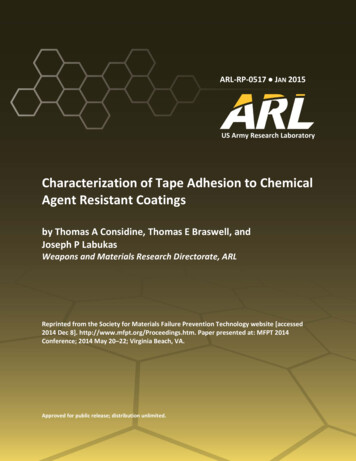
Metal EscalationEscalation: Metal contaminationContamination identification:VPD ICP-MSPartitioning test: metal wipe testHypothesis: micro-arcingVerify root cause: fix short andreplace ceramic rodsEscalation resolved ElementAlCaCrCuFeMgNiKNaZn300mm Wafer2DL E10 3400.3770.113 PartitioningTestsBULK CONCENTRATION(atoms/cm 3)ElementBaBCaCoCuFeLiMgMnNiKNaSrSnTiWZnZrSARIS (10 µm) of ceramic insulator rodsVPD ICP-MS ResultsElementDLng/cm 2Ceramic A Ceramic B Ceramic E157.7E156.0E164.0E131130Area 12590358000452605420Area 2659071500812500Area 3915000Area 60002004002501200Metal wipe test resultsReducing Contamination2006200
Starting Materials CharacterizationOrganic outgassing sourcesPart DescriptionMaterial/CompositionCable CoaxialConductor Material: Silver Plated Copper Covered Steel (SPCCS); Insulation Material: Tetrafluoroethylene(TFE); Outer Shield Material: Silver Plated Copper; Outer Jacket Material: Fluorinated EthylenePropoyleneConnector for Coaxial PlugShell: Brass; Plug Body: Brass; Cable Clamp, Inner Sleeve, Washer or Nuts: Brass; Male Crimp Contacts:Bronze; Female Crimp Contacts: BronzeConnector for Coaxial Plug - 50 OhmOuter Shell: Brass, Stainless Steel, Aluminum Alloy, PEEK; Sealing Resin: Epoxy; Grounding Crown:Bronze, Beryllium Copper, Stainless Steel; Latch Sleeve: Special Brass, Stainless Steel; LockingWasher: Bronze; Hexagonal or Round Nut: Brass, Stainless Steel, Aluminium alloy; Other MetallicComponents: Brass, Stainless Steel; O-Ring and Gaskets: SiliconeCable CoaxialConductor Material: Silver Plated Copper Covered Steel; Insulation Material: Tetrafluoroethylene (TFE);Outer Shield Material: Silver Plated Copper Covered Steel; Outer Jacket Material: Fluorinated EthylenePropyleneConnector Socket, Open EndContact Material: Copper Alloy; Contact Underplating: Nickel; Insulation Material: Glass Filled Polyester(PBT)Sensor, Light/DarkMaterials: Polybutylene Phthalate (PBT); Cover: Polycarbonate; Emitter: PolycarbonateWire, 28 AWG, Black *Conductor Material: Silver Plated Copper; Insulation Material: Tetrafluoroethylene (TFE)Connector, Socket 26 Position, Open EndContact Material: Copper Alloy; Contact Underplating: Nickel; Insulation Material: Glass Filled Polyester(PBT)Shrink Tubing, 3/32 ID, Kyanr, ClearPolyvinylidene FluorideWire, 28 AWG, Black *Conductor Material - Silver Plated Copper, Insulation Material: Fluorinated Ethylene Propylene (FEP)Cable, High Voltage, 22 AWG, StrandedSilver Plated Conductor, Overlapping tapes of GoreTM Corona Resistant (PTFE)Terminal Ring, 12-10 AWGElectrolytically Refined CopperRED: material that may outgasReducing Contamination
Bulk Organic CharacterizationThermal Desorption Gas Chromatography Mass Spectrometry (TD-GCMS)Primary (Tube) DesorptionDesorb FlowCarrier GasInletTo MassDetectorCold TrapHot Sample Tube(400OC) CarrierGas InletIn-instrument outgassinga Tenax tubea For medium to high outgassing material Off-line outgassinga Quartz tubea Larger sample to increase detection limita For low outgassing materialReducing ContaminationGCAnalyticalColumn
Surface Cleanliness of Tool ComponentsTarget contaminants depend on the history of the part Starting materiala Gross contaminationa Not a concern as the material will be machined and later cleaneda Bulk contamination is more critical Machined parta Major contamination is from machine oil, metal cross-contamination,water and solvent residue, oven, etc.a Machine shops are not semiconductor clean environmentsa Contaminants of concern: Organic Particle Metal Anion After Precision cleaninga Minor contaminationa Typically from handling, environment, packaging, etc.a Contaminants of concern: Metal Particle Organic Aniona)b)Precision cleaning is defined as “The removal of undesirable contaminantsto a pre-determined measurable standard without introducing newcontaminants or changing the surface integrity”Precision cleaning dictates the tool BOM must have a cleanlinessspecificationReducing ContaminationTrend is formachine shopsto pre-cleanin-house,outsourcePrecisionCleaning andsend partsdirectly to thecustomer
Surface Contamination Characterization Applicationa Machined parts – coupons and first articlea New and used parts after Precision Cleaning Specificationaaaa Effective in removing surface contamination for analysisMust be damage-free with minimal material lossPerformed on small and large parts (300mm and 450mm)Part may be returned to the field after testingCurrent test methods involving wet chemistrya Imparts minimal damage to the surfacea No restriction on part sizea Effective in removing metals, anions and organic residues since they have ahigh solubility in liquid chemistriesa High efficiency in particle removal Adjusting the surface zeta potential (e.g. pH) to reduce the adhesion force Reducing megasonic energy to improve the particle removal performance and toreduce damageReducing Contamination
Chemical Surface CharacterizationSEMICONDUCTORPROCESS OPTIMAWafer ProductionThermal Oxidation/FilmPhotolithographyEtchDoping/Ion ImplantDielectric DepositionCMPMetalOrganicIonicParticleAcid extraction & ICP-MS1UPW extraction & ICP-MS2Drop scan etch & ICP-MS3Solvent extraction & GC-MS4Solvent extraction & NVR/FTIR5UPW extraction & Ion Chromatography6UPW extraction & LPC (SEM-EDS)7Test methods are often referredto as Leach or ExtractableNonDestructivetestproceduresKEY1. Metal: whole surface extraction2. Metal: UPW extraction efficiency less than using acidü No surface damage3. Metal: localized surface extraction using acidü Can be performed directly on tool component surface4. Organic: solvents to extract organic residue and UPW/TOC5. Organic: weight of NVR and organic identification6. Ionic: whole surface extraction7. Particle: whole surface particle counting and identificationCeramic showerhead8”SEM with large samplechamberReducing Contamination
Surface Extraction of Components Provides surface cleanliness verification and quantification of contaminantsa Compare vendorsa Qualify components to a cleanliness specificationa Ensure components and coatings are compatible to a process – temp, exposure time,acid/alkali, HV, etc.a Lot to lot quality control General rulea A less aggressive leach results in lower detectable contaminant levela A more aggressive leach results in higher detectable contaminant level Static leach conditionsa Component is soaked in UPW or chemical solutiona Standard test condition Ambient temperature, UPW and short extractiontime of 1h to 1 daya Semi-Aggressive Elevated temperature 50C, UPW and shortextraction time of 1 -2ha Aggressive High temperature, extended extraction time and/or use of chemicals Chemical for 7 days at ambient temperature UPW at 85C for 7 days (SEMI F-57)Reducing ContaminationCeramic rings
12Surface Conc. (x10 mol/cm 2)Surface Extraction of Packaging FilmsNatural PE50Antistatic PEAntistatic Nylon40302010-FCl--NO3-SO4 NaIonic SpeciesNH4 KMg2 Ca2 Lin S and Graves S, Micro, October, 1998Rule of thumb, the cleanliness level of packaging films should be at least3-5x lower than the cleanliness specifications of the parts to be packaged Natural and antistatic PE generally exhibit acceptable levels of ionic cleanliness;generally shown to also be oil and amine-free Most available films, including natural PE, are not adequate for packaging tool partsrequiring very low levels of hydrocarbon contaminants. FEP is acceptable but costs 15xmore than PE. Bagging requirements: a Double bagging for all parts except tool parts (robotic blades, handling systems, chucks) thatare exposed to the wafer must be triple baggeda Bagging material must cover all outer tool surfacesReducing Contamination
Physical Surface CharacterizationSEMICONDUCTORPROCESS OPTIMAWafer ProductionThermal Oxidation/FilmPhotolithographyEtchDoping/Ion ImplantDielectric DepositionCMPMetal1AES2TXRF *3VPD ICP-MS *4SurfaceSIMS5TOF-SIMSOrganic Full Wafer Outgassing TD-GCMS * 6TOF-SIMS7XPS8Ionic XPS9Particle FE-AES10KEY1. AES: 30-50Å, at% DL, elemental survey, conducting surface2. TXRF: 30-50Å, 109-1015 at/cm2, elemental survey, flat surface3. VPD ICP-MS: SiO 2, 107-1015 at/cm2, elemental survey4. SurfaceSIMS: any depth, 108-1015 at/cm2, elemental specific5. TOF-SIMS: ML, 10 7-1015 at/cm2, elemental survey, any surface6. Full Wafer Outgassing: ng/cm 2, organic survey7. TOF-SIMS: monolayer, ng/cm 2, organic survey, any surface8. XPS: 30-50Å, at% DL, elemental/chemical state survey,non-conducting surface10. FE-AES: 10nm spatial resolution for elemental characterizationMostly used for coupons,wafers and R&DDestructivetechniques* non-destructivewafer testSectioning ceramic showerheadX-section of openingOther UV (black) light: visual inspection for residue polymer on the surface Profilometry: surface roughness and surface layer thickness (Fisherscope)Reducing Contamination
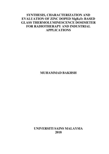
Tool Particle SpecificationParticle SpecificationTechnology NodeAnalytical TestWafer Front Sidea 90 nm90 nmFull pipeline test, 6 wafers,150 cycles, KLA SP265 nm0.2 @ 90 nm(0.0002/cm2 pwp)Wafer Back SideaFull Contact 1500 @ 90 nm(2.8/cm2 pwp)Tool SurfacebNon-Critical Surface 10/in2 @ 0.3 µmCritical Surface 1/in2 @ 0.3 µmLow Contact 500 @ 90 nmEdge Contact 20 @ 90 nm45 nma) Tool with closable holes for insertion of sample heads forairborne qualification purposes and FAb) Particles on tool component surfaces and skin shall bemeasured using a surface particle detector23LocationOff LLBridgeFront LL1Mainframe Surfaces54 9(particles/in² @ 0.3 µm)Painted 10-80Granite 10-95Anodized 10-60Aluminum 15-90Plexiglass 10-90TiSiAlReducing Contamination The Al/Ti particle originating from aninteraction of an etch by-product ofthe TiN adhesion layer and theprocess chamber hardware81110 12161315Nest/low surfaceNest/high surfaceTransfer arm/frontTransfer arm/backArea 0.3 um 0.5 um 1 um 5 um10.2100026.923.541.6 0.0832.381.830.96 uck/backChuck/frontStage/rearStage/frontArea 0.3 um 0.5 um100.0801100120.210.13130.080LocationChamber lidChamber lidArea15160.0800.040.5800001 um 5 um000000000.3 um 0.5 um 1 um 5 um0.040000.0400010 um00.040.33000010 um000010 um00
Tool Metal SpecificationAnalytical TestaTechnology NodeMetal SpecificationbFull Pipeline test, 6wafers by 100 cycles 90 nmVPD-ICP-MS 5E11 at/cm2 per metal90 nmVPD-ICP-MS 1E10 at/cm2 per metal65 nmVPD-ICP-MS 1E10 at/cm2 per metal45 nmVPD-ICP-MS 5E9 at/cm2 per metalHigh DetectionGross Contaminationa) VPD ICP-MS detects Ca, K,Na, Al, Fe, Cr, Ni, Zn, Li,Be, Mg, V, Mn, Co, Ga, Sr,Zr, Mo, Cd, Sn, Sb, Ba, Ti,Y, Rb, In, Ce, Th, U, Cu.b) Target metals include Gp 1metals (Fe, Ni, Cu, Cr, Co,Hf, and Pt; can dissolve inSi and form silicides) and/orGp 2 metals (Ca, Ba, Feand Sr; GOI killers)Low DetectionProcessToolMetalWaferSARISSTANDARD TXRFSIMS PROFILESurfaceSIMSTOF Reducing ContaminationUncleanedCleaned
Tool Organic SpecificationAnalytical TestaTechnology NodeOrganic Specificationb, c, dOrganic component Sum C7tested in Dynamic ModeReducing Contamination212Cyclo(Me 2SiO)12POSSIBLECYCLO(Me SiO)1010112CYCLO(MeSOi11)Cyclo(Me 2SiO)92CYCLOM(eSOi)28Cyclo(Me 2SiO)820.00CYCLOM( eSiO)CYCLOM( e2SiO)7625215.00Cyclo(Me 2SiO)733.00 (33.00 to 700.00): 70052605.DCyclo(Me 2SiO)5FluoroalkylEtherCYCLCyclo(MeOM(eSOi)2 SiO)6CYCLOM( eSiO)3210.00 Ethyl HexanolIon5e 074.8e 074.6e 074.4e 074.2e 074e 073.8e 073.6e 073.4e 073.2e 073e 072.8e 072.6e 072.4e 072.2e 072e 071.8e 071.6e 071.4e 071.2e 071e 0780000006000000400000020000000Time-- 5.002AbundanceCyclo(Me 2SiO)9Full Wafer TD-GCMSCYCLO(MeSOi)Sample ID: CHUCK- Al 2O3, 1/22/07 (19:00 HOURS AT 1.2 x 10- 7 TORR)Cyclo(Me 2SiO)Figure 1FLUOROALKYLETHER(m/z:691,191,692,853,35)SEMI MF1982-1103Full wafer outgassing TD GC-MSCyclo(Me 2SiO)4 Cyclo(Me 2SiO)FluroalkyletherCyclo(Me 2SiO)3 2 ng/cm 2 0.1 MLML 5ÅML 1015 at/cm2Fluroalkylether2 RGACyclo(Me 2SiO)4a) ASTM F1982-99 "Standard Test Method forAnalyzing Organic Contaminants on SiliconWafer Surfaces by TD-GC.“ This method isdesigned to sample semivolatile organic airbornemolecular contamination adsorbed onto thepolished face of the Si waferb) Wafer side specificc) 10 ng/cm2 affectsadhesion 10 ng/cm2CYCLO(MeSOi)45 nm 15 ng/cm2CYCLO(MeSOi) ETHYLHEXANOL65 nm 20 ng/cm2d8-TOLUENE(INTERNALSTANDARD)90 nm 20 ng/cm21) Load Lock Partition test: 1x2 wafers, 200cycles (100 cycles each), 30 minsexposure/wafer.2) Organic Pipeline test: 2x2 wafers, 120cycles (30 cycles each), 20 minsexposure/wafer.3) Full wafer outgassing by TD-GC-MSaC8-HYDROCARBONS 90 nm25.0030.0035.00
Tool Escalation Case StudyTOOL ESCALATIONHigh1 SMC carbon levelexceeding tool acceptanceMetal spec is 5E10level of 2 at%by XPS2at/cm by TXRFTOOLOBSERVATIONSROOT CAUSEFull Wafer TD-GCMS tospecies.27 carbon at% on witness identify AMC-MC65FTIR and TOF-SIMS toExcess lubricant in toolResidualHCl from insufficient Flame retardant Padwafercompresses andidentify lubricantrinsing?outgasses at edgecompound.High Cl TXRF level exceeding5E13 Cl at/cm2 on5E10 at/cm2 spec forwitness waferacceptanceClFAILURE ANALYSISDetermine inorganic Clusing IC or organic Cl usingGCMS. O-Cl confirmedfollowed by speciesFoam isolation padsidentification using FullWafer TD-GCMS indynamic testing mode.REMEDY7Remove excesslubricantBlue pad outgassBlk pad not outgasTD-GCMS verificationof alternativematerialsVPD ICP-MS monitoringwas critical as Pb is notHigh Pb level by VPD ICP-MSCity water sourceFirstused“look”HottoolSARIS/SEM-EDX5E11 Pb at/cm2 ondetected by TXRF usingWDIW flush ofexceeding 5E10 at/cm2 toolduring manufacturing ofwitness wafersource. IsolationtubingSPCPVDF tubingexperiments identified root3Static wafer show no Cl by TXRFsource. 4INORGANICORGANICDynamic wafer testing show ClSEM-EDX identifiesorganoHigh replacement rate ofTD-GCMS verificationSi as contaminant onOutgassing of Gelpakbeam aperture on ionReduced beam currentLOW CONC.LOW CONC.of alternativeaperture.TD-GCMSaperture packagingimplanterpackagingidentifiesorganic species.VPD ICP -MSTOF-SIMSTXRF, VPD TXRFFW TD -GCMSUPW – ICTD GC-MSUPW-ICP-MS8 This is a difficult problem to solve because no one did anything wrong. In fact, everyone involved did whatdAcid-ICP-MSTOF-SIMSthey thought was the right thing to expeditethe PM and keep on schedule.Quad-SIMSReducing Contamination
Organic Tool Optima Escalation Verify Root Cause Repeat static or dynamicwafer exposurePerform FW TD-GCMS PerformanceContaminationa 2 at% carbon (XPS)a 5E10 Cl atoms/cm2 (TXRF)Resolve Escalation Partitioning Test Select materials, inside andoutside of the tool, to test fororganic outgassinga Identify and quantifyorganic speciesWipe test for local testing of toolcomponentsReducing ContaminationRepeat performance orcontamination testContamination Identification SMC-SMOrg - FW TD-GCMSa Static: 2 to 24 h exposurea Dynamic: 20 to 100 cyclesa Identifies and quantifies organicspeciesa Ranks organic concentrations intogroups – low (C7-C10), medium( C10 – C20) and high boilers( C20)
Conclusion Tool contamination is a major cause of many fab escalationsHigh yield processing requires clean tools and clean manufacturingprocedures. This dictates there must be cleanliness specification for in-tools,precision cleaning, packaging and on the process floor (Ex: housekeepingcleanliness specifications)Unfortunately, cleanliness specifications are often lacking and this impoundsthe difficulty to resolve contamination escalations, both in the tool and on theprocess floorBulk and surface contamination of starting material and tool components areequally importantTarget contaminants differ for a part and depends on its life cycle – from rawmaterial, coupon, first article, new part, used part, etc.Non-destructive chemical characterization is possible on production tool partsDestructive physical characterization on production tool parts is an option if youare willing to sacrifice the partCleanliness verification of tool BOM is instrumental to optimizing processyields. Advanced technology node processes require stringent cleanlinessspecifications, lower analytical detection limits and clean handling techniqueRe
VPD ICP-MS 3 SurfaceSIMS 4 TOF-SIMS 5 Organic Full Wafer Outgassing TD-GCMS 6 TOF-SIMS 7 XPS 8 Ionic XPS 9 Particle FE-AES 10 SEMICONDUCTOR PROCESS OPTIMA Wafer Production Thermal Oxidation/Film Photolithography Etch Doping/Ion Implant Dielectric Deposition CMP Physical Surface Characte