Transcription
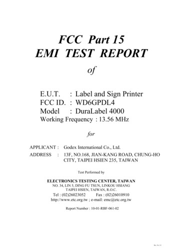
FCC Part 15EMI TEST REPORTofE.U.T. : Label and Sign PrinterFCC ID. : WD6GPDL4Model : DuraLabel 4000Working Frequency : 13.56 MHzforAPPLICANT :Godex International Co., Ltd.ADDRESS13F, NO.168, JIAN-KANG ROAD, CHUNG-HOCITY, TAIPEI HSIEN 235, TAIWAN:Test Performed byELECTRONICS TESTING CENTER, TAIWANNO. 34, LIN 5, DING FU TSUN, LINKOU HSIANGTAIPEI HSIEN, TAIWAN, R.O.C.Tel : (02)26023052Fax : (02)26010910http://www.etc.org.tw ; e-mail: emc@etc.org.twReport Number : 10-01-RBF-061-02Rev. No 1.0
ETC Report No.:10-01-RBF-061-02FCC ID.: WD6GPDL4TEST REPORT CERTIFICATIONApplicant: Godex International Co., Ltd.13F, NO.168, JIAN-KANG ROAD, CHUNG-HO CITY,TAIPEI HSIEN 235, TAIWANManufacture: Godex International Co., Ltd.13F, NO.168, JIAN-KANG ROAD, CHUNG-HO CITY,TAIPEI HSIEN 235, TAIWANDescription of EUT:a) Type of EUTb) Trade Namec) Model No.d) FCC IDe) Working Frequencyf) Power SupplyRegulation Applied: Label and Sign Printer: Graphic Products: DuraLabel 4000Motor Model:1. PM42L-048-XTB3(PM42L-048-XTB3A)2. M42SP-5N3. T4216R07: WD6GPDL4: 13.5608 MHz: Adapter: WDS060240I/P: 100-240V 1.6A 50-60HzO/P: 24V 2.5A: FCC Rules and Regulations Part 15 Subpart C (2008)I HEREBY CERTIFY THAT; The data shown in this report were made in accordance with theprocedures given in ANSI C63.4 and the energy emitted by the device was founded to be withinthe limits applicable. I assume full responsibility for accuracy and completeness of these data.Rev. No 1.0
ETC Report No.:10-01-RBF-061-02FCC ID.: WD6GPDL4Note : 1. The results of the testing report relate only to the items tested.2. The testing report shall not be reproduced except in full, without the writtenapproval of ETC.Date Test Item Received: Jan. 13, 2010Date Test Campaign Completed : Mar. 02, 2010Date of Issue: Mar. 03, 2010Test Engineer:( Vincent Chang, Engineer )Check By:( Charles Wang, Supervisor )Approve & Authorized:( Will Yauo, Manager )EMC Dept. II of ELECTRONICSTESTING CENTER, TAIWANRev. No 1.0
ETC Report No.:10-01-RBF-061-02Table of ContentsFCC ID.: WD6GPDL4Page1. GENERAL INFORMATION . 11.1PRODUCT DESCRIPTION . 11.2 CHARACTERISTICS OF DEVICE: . 11.3 TEST METHODOLOGY . 11.4 TEST FACILITY . 12. DEFINITION AND LIMITS . 22.12.22.32.42.5DEFINITION . 2REQUIREMENT FOR COMPLIANCE . 3RESTRICTED BANDS OF OPERATION . 5LABELING REQUIREMENT . 5USER INFORMATION . 63 SYSTEM TEST CONFIGURATION . 73.1 JUSTIFICATION . 73.2 DEVICES FOR TESTED SYSTEM . 74. RADIATED EMISSION MEASUREMENT . 84.1 APPLICABLE STANDARD. 84.2 MEASUREMENT PROCEDURE. 84.3 TEST DATA . 104.3.1 Below 30MHz . 104.3.2 Harmonics in 30MHz – 1GHz. 114.3.3 Spurious Emissions (RFID Off). 134.4 FIELD STRENGTH CALCULATION . 154.5 RADIATED TEST EQUIPMENT. 154.8 MEASURING INSTRUMENT SETUP . 154.9 RADIATED MEASUREMENT PHOTOS. 165 FREQUENCY STABILITY MEASUREMENT. 175.15.25.35.4PROVISIONS APPLICABLE . 17MEASUREMENT PROCEDURE. 17MEASUREMENT INSTRUMENT . 18MEASUREMENT DATA . 196. CONDUCTED EMISSION MEASUREMENT . 206.16.25.36.46.56.6STANDARD APPLICABLE . 20MEASUREMENT PROCEDURE. 20CONDUCTED EMISSION DATA . 21RESULT DATA CALCULATION . 27CONDUCTED MEASUREMENT EQUIPMENT . 27PHOTOS OF CONDUCTION MEASURING SETUP . 287 ANTENNA REQUIREMENT . 297.1 STANDARD APPLICABLE . 297.2 ANTENNA CONSTRUCTION . 29Rev. No 1.0
ETC Report No.:10-01-RBF-061-02Sheet 1 of 29 SheetsFCC ID.: WD6GPDL41. GENERAL INFORMATION1.1 Product Descriptiona) Type of EUTb) Trade Namec) Model No.d) FCC IDe) Working Frequencyf) Power Supply: Label and Sign Printer: Graphic Products: DuraLabel 4000Motor Model:1. PM42L-048-XTB3(PM42L-048-XTB3A)2. M42SP-5N3. T4216R07: WD6GPDL4: 13.56 MHz: Adapter: WDS060240I/P: 100-240V 1.6A 50-60HzO/P: 24V 2.5A1.2 Characteristics of Device:A 13.56MHz RFID module was installed in the Label and Sign Printer.1. RF Transmit Frequency: 13.56MHz2. Supported Transponder: ISO15693 Complied Read/ Write Transponders; TI HF-IPlus; TI HF-I Pro/Standard; I-Code II3. Antenna impedance: 50 ohm Loop Antenna4. Communication Protocol: The Nation standard UART format1.3 Test MethodologyBoth conducted and radiated emissions were performed according to the proceduresillustrated in ANSI C63.4 (2003). Other required measurements were illustrated inseparate sections of this test report for details.The RFID transmitter was installed in a class A printer. Tests were conducted with thefollowing method to determine the compliance.1. Test with the printer working and RFID ON. FCC 15.225 limits apply to RFID signals.2. Test with the printer working but RFID OFF. FCC class A limits apply to the printer.The motor inside the printer has three options. Tests were conducted to each one of themotors.1.4 Test FacilityThe open area test site and conducted measurement facility used to collect the radiateddata is located on the roof top of Building at NO.34, LIN 5, DINGFU TSUEN, LINKOUSHIANG TAIPEI COUNTY, TAIWAN, 24442, R.O.C.This site has been fully described in a report submitted to your office, and accepted in aletter dated Aug. 05, 2008.Rev. No 1.0
ETC Report No.:10-01-RBF-061-02Sheet 2 of 29 SheetsFCC ID.: WD6GPDL42. DEFINITION AND LIMITS2.1 DefinitionUnintentional radiator:A device that intentionally generates and radio frequency energy for use within the device,or that sends radio frequency signals by conduction to associated equipment via connectingwiring, but which is not intended to emit RF energy by radiation or induction.Class A Digital Device:A digital device which is marketed for use in commercial or business environment;exclusive of a device which is market for use by the general public, or which is intended tobe used in the home.Class B Digital Device :A digital device which is marketed for use in a residential environment notwithstandinguse in a commercial, business of industrial environment. Example of such devices that aremarketed for the general public.Note : A manufacturer may also qualify a device intended to be marketed in a commercial,business, or industrial environment as a Class B digital device, and in fact isencouraged to do so, provided the device complies with the technical specificationsfor a Class B Digital Device. In the event that a particular type of device has beenfound to repeatedly cause harmful interference to radio communications, theCommission may classify such a digital device as a Class B Digital Device,Regardless of its intended use.Intentional radiator:A device that intentionally generates and emits radio frequency energy by radiation orinduction.Rev. No 1.0
ETC Report No.:10-01-RBF-061-02Sheet 3 of 29 SheetsFCC ID.: WD6GPDL42.2 Requirement for Compliance(1) Conducted Emission RequirementExcept for Class A digital devices, for equpment that is designed to be connected tothe public utility (AC) power line, the radio frequency voltage that is conducted backonto the AC power line on any frequency or frequencies within the band 150kHz to30MHz shall not exceed the limits in the following table, as measured using a 50µH/50ohms line impedance stabilization network (LISN). Compliance with the provisions ofthis paragraph shall be based on the measurement of the radio frequency voltagebetween each power line and ground at the power terminal. The lower limit applies atthe band edges.FrequencyMHzQuasi PeakdBμV0.15 - 0.566-56*0.5 - 5.0565.0 - 30.060* Decreases with the logarithm of the frequencyAveragedBμV56-46*4650(2) Radiated Emission Limits:According to 15.225, the requirement of radiated emission is:(a) The field strength of any emissions within the band 13.553-13.567 MHz shallnot exceed 15,848 microvolts/meter at 30 meters.(b) Within the bands 13.410-13.553 MHz and 13.567-13.710 MHz, the fieldstrength of any emissions shall not exceed 334 microvolts/meter at 30 meters.(c) Within the bands 13.110-13.410 MHz and 13.710-14.010 MHz the field strengthof any emissions shall not exceed 106 microvolts/meter at 30 meters.(d) The field strength of any emissions appearing outside of the 13.110-14.010 MHzband shall not exceed the general radiated emission limits in § 15.209.According to § 15.209 Radiated emission limits, general requirements.(a) Except as provided elsewhere in this Subpart, the emissions from an intentionalradiator shall not exceed the field strength levels specified in the following table:FrequenciesField StrengthMeasurement(MHz)(microvolts/meter)Distance (meters)0.009 – 0.4902400/F(kHz)3000.490 – 1.70524000/F(kHz)301.705 – 30.0303030 – 88100 **388 – 216150 **3216 – 960200 **3Above 9605003** Except as provided in paragraph (g), fundamental emissions from intentionalRev. No 1.0
ETC Report No.:10-01-RBF-061-02Sheet 4 of 29 SheetsFCC ID.: WD6GPDL4radiators operating under this Section shall not be located in the frequency bands 5472 MHz, 76-88 MHz, 174-216 MHz or 470-806 MHz. However, operation withinthese frequency bands is permitted under other sections of this Part, e.g., Sections15.231 and 15.241.As shown in 15.35(b), for frequencies above 1000MHz, the field strength limits arebased on average detector, however, the peak field strength of any emission shall notexceed the maximum permitted average limits, specified above by more than 20 dBunder any condition of modulation.(3) Frequency Stability Limit:According to 15.225, the requirement of frequency stability is:(e) The frequency tolerance of the carrier signal shall be maintained within /0.01% of the operating frequency over a temperature variation of –20 degrees to 50 degrees C at normal supply voltage, and for a variation in the primarysupply voltage from 85% to 115% of the rated supply voltage at a temperature of20 degrees C. For battery operated equipment, the equipment tests shall beperforme using a new battery.(4) Antenna RequirementFor intentional device, according to §15.203, an intentional radiator shall be designedto ensure that no antenna other than that furnished by the responsible party shall beused with the device.Rev. No 1.0
ETC Report No.:10-01-RBF-061-02Sheet 5 of 29 SheetsFCC ID.: WD6GPDL42.3 Restricted Bands of OperationOnly spurious emissions are permitted in any of the frequency bands listed below :MHzMHzMHzGHz0.090 - 0.1100.495 - 0.505 **2.1735 - 42-16.42316.69475 - 16.6952516.80425 - 1.94123-138149.9-150.05156.52475 - 36.5Above 38.6** : Until February 1, 1999, this restricted band shall be 0.490-0.510 MHz2.4 Labeling RequirementThe device shall bear the following statement in a conspicuous location on the device:This device complies with part 15 of the FCC Rules. Operation is subject to the followingtwo conditions: (1) This device may not cause harmful interference, and (2) this devicemust accept any interference received, including interference that may cause undesiredoperation.Rev. No 1.0
ETC Report No.:10-01-RBF-061-02Sheet 6 of 29 SheetsFCC ID.: WD6GPDL42.5 User InformationThe users manual or instruction manual for an intentional or unintentional radiator shallcaution the user that changes or modifications not expressly approved by the partyresponsible for compliance could void the user's authority to operate the equipment.For a Class B digital device or peripheral, the instructions furnished the user shall includethe following or similar statement, placed in a prominent location in the text of the manual.The Federal Communications Commission Radio Frequency Interference Statementincludes the following paragraph.This equipment has been tested and found to comply with the limits for a Class B DigitalDevice, pursuant to Part 15 of the FCC Rules. These limits are designed to providereasonable protection against harmful interference in a residential installation.This equipment generates, uses and can radiate radio frequency energy and, if not installedand used in accordance with the instruction may cause harmful interference to radiocommunication. However, there is no guarantee that interference will not occur in aparticular installation.If this equipment does cause harmful interference to radio or television reception, whichcan be determined by turning the equipment off and on, the user is encouraged to try tocorrect the interference by one or more of the following measures:-- Reorient or relocate the receiving antenna.-- Increase the separation between the equipment and receiver.-- Connect the equipment into an outlet on a circuit different from that to which thereceiver is connected.-- Consult the dealer or an experienced radio / TV technician for help.Rev. No 1.0
ETC Report No.:10-01-RBF-061-02Sheet 7 of 29 SheetsFCC ID.: WD6GPDL43 SYSTEM TEST CONFIGURATION3.1 JustificationAll measurements were intentional to maximum the emissions from EUT by varying theconnection cables, therefore, the test result is sure to meet the applicable requirement.3.2 Devices for Tested SystemDeviceManufactureLabel and Sign Godex International Co.,Printer*Ltd.Model / FCC ID.DescriptionDuraLabel 4000 / 1.5m Unshielded ACWD6GPDL4Adapter0.8m Unshielded USBCableFP7561.5m Unshielded AC PowerCord1.5m Unshielded VGACableM/T6824-RCV1.5m Unshielded AC rdMousePrinterIBMIBMEPSONKB-0225MU29JStylus 7001.5m Unshielded ACAdapter Cable1.5m Unshielded PS2 Line1.5m Unshielded PS2 Line1.5m Unshielded AC PowerCord1.5m Unshielded ParallelCableRemark “*” means equipment under test.Rev. No 1.0
ETC Report No.:10-01-RBF-061-02Sheet 8 of 29 SheetsFCC ID.: WD6GPDL44. RADIATED EMISSION MEASUREMENT4.1 Applicable StandardFor periodic operation intentional radiator, the radiated emission shall comply with §15.231(b).According to 15.225, the requirement of radiated emission is:(a) The field strength of any emissions within the band 13.553-13.567 MHz shall notexceed 15,848 microvolts/meter at 30 meters.(b) Within the bands 13.410-13.553 MHz and 13.567-13.710 MHz, the field strength ofany emissions shall not exceed 334 microvolts/meter at 30 meters.(c) Within the bands 13.110-13.410 MHz and 13.710-14.010 MHz the field strength ofany emissions shall not exceed 106 microvolts/meter at 30 meters.(d) The field strength of any emissions appearing outside of the 13.110-14.010 MHzband shall not exceed the general radiated emission limits in § 15.209.4.2 Measurement Procedure1. Setup the configuration per figure 1 and 2 for frequencies measured below and above 1GHz respectively.2. For emission frequencies measured below 1 GHz, a pre-scan is performed in a shieldedchamber
Rev. No 1.0 FCC Part 15 EMI TEST REPORT of E.U.T. : Label and Sign Printer FCC ID. : WD6GPDL4 Model :


![[ANS AQT80] - FCC ID](/img/3/user-manual-pdf-2735955.jpg)
![Ticket: # 3011470 - Re: [FCC Complaints] Re: Billing](/img/9/fcc-complaints-from-alabama-residents-2.jpg)