Transcription
EMI Shielding Theory& Gasket Design GuideSECTION CONTENTSPAGETheory of shielding and gasketing192Conductive elastomer gasket design196Gasket junction design196Corrosion198Selection of seal cross section202General tolerances204Gasket mounting choices205Fastener requirements206Designing a solid-O conductive elastomer gasket-in-a-groove209Mesh EMI gasketing selection guide214Glossary of terms218Part number cross reference index220US Headquarters TEL (1) 781-935-4850 FAX (1) 781-933-4318 www.chomerics.comEurope TEL (44) 1628 404000 FAX (44) 1628 404090Asia Pacific TEL (852) 2 428 8008 FAX (852) 2 423 8253South America TEL (55) 11 3917 1099 FAX (55) 11 3917 0817191
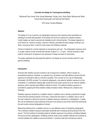
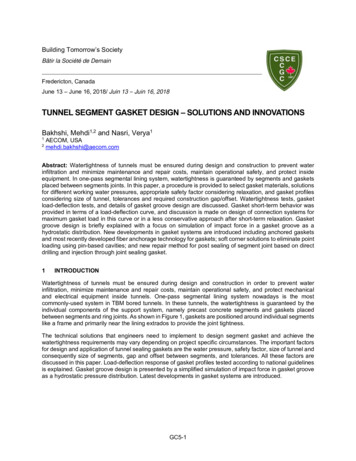
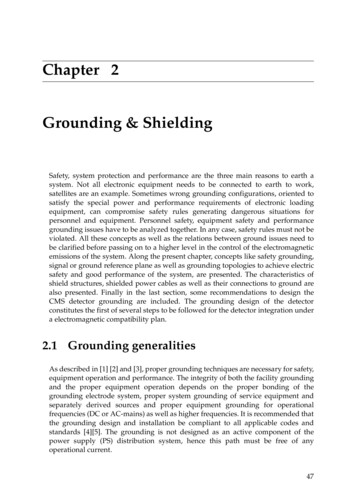
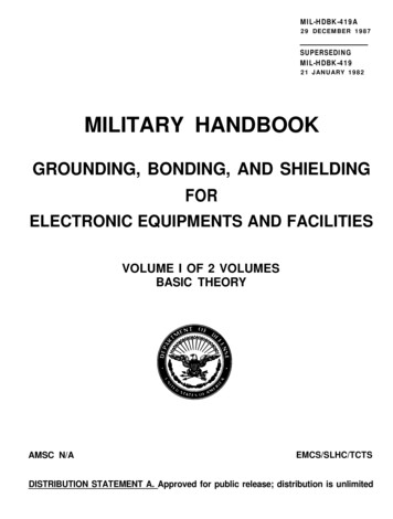
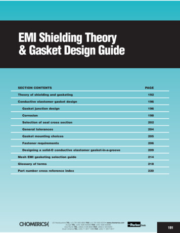
EMI Shielding TheoryTheory of Shieldingand GasketingFundamental ConceptsA knowledge of the fundamentalconcepts of EMI shielding will aidthe designer in selecting the gasketinherently best suited to a specificdesign.All electromagnetic waves consistof two essential components, amagnetic field, and an electric field.These two fields are perpendicularto each other, and the direction ofwave propagation is at right anglesto the plane containing these twocomponents. The relative magnitudebetween the magnetic (H) field andthe electric (E) field depends uponhow far away the wave is from itssource, and on the nature of thegenerating source itself. The ratioof E to H is called the waveimpedance, Zw.If the source contains a largecurrent flow compared to its potential,such as may be generated by aloop, a transformer, or power lines,it is called a current, magnetic, orlow impedance source. The latterdefinition is derived from the factthat the ratio of E to H has a smallvalue. Conversely, if the sourceoperates at high voltage, and onlya small amount of current flows, thesource impedance is said to behigh, and the wave is commonlyreferred to as an electric field. Atvery large distances from thesource, the ratio of E to H is equalfor either wave regardless of itsorigination. When this occurs, thewave is said to be a plane wave,and the wave impedance is equalto 377 ohms, which is the intrinsicimpedance of free space. Beyondthis point all waves essentially losetheir curvature, and the surfacecontaining the two componentsbecomes a plane instead of asection of a sphere in the caseof a point source of radiation.The importance of waveimpedance can be illustrated byconsidering what happens when anelectromagnetic wave encounters adiscontinuity. If the magnitude of the192wave impedance is greatly differentfrom the intrinsic impedance of thediscontinuity, most of the energy willbe reflected, and very little will betransmitted across the boundary.Most metals have an intrinsicimpedance of only milliohms. Forlow impedance fields (H dominant),less energy is reflected, and moreis absorbed, because the metalis more closely matched to theimpedance of the field. This is whyit is so difficult to shield againstmagnetic fields. On the other hand,the wave impedance of electricfields is high, so most of the energyis reflected for this case.Consider the theoretical caseof an incident wave normal tothe surface of a metallic structureas illustrated in Figure 1. If theconductivity of the metal wall isinfinite, an electric field equal andopposite to that of the incidentelectric field components of thewave is generated in the shield.This satisfies the boundary conditionthat the total tangential electric fieldmust vanish at the boundary. Underthese ideal conditions, shieldingshould be perfect because the twofields exactly cancel one another.The fact that the magnetic fields arein phase means that the current flowin the shield is doubled.xEiPerfectlyConductivePlane z 0HiHrEErHzyFigure 1 Standard Wave Pattern of aPerfect Conductor Illuminated by aNormally Incident, X Polarized PlaneWaveShielding effectiveness of metallicenclosures is not infinite, becausethe conductivity of all metals is finite.They can, however, approach verylarge values. Because metallicshields have less than infiniteconductivity, part of the field istransmitted across the boundaryand supports a current in the metalas illustrated in Figure 2. Theamount of current flow at any depthin the shield, and the rate of decayis governed by the conductivity ofthe metal and its permeability. Theresidual current appearing on theopposite face is the one responsiblefor generating the field which existson the other side.EiEtJoJtFigure 2 Variation of Current Densitywith Thickness for Electrically ThickWallsOur conclusion from Figures 2and 3 is that thickness plays animportant role in shielding. Whenskin depth is considered, however,it turns out that thickness is onlycritical at low frequencies. At highfrequencies, even metal foils areeffective shields.The current density for thin shieldsis shown in Figure 3. The currentdensity in thick shields is the sameas for thin shields. A secondaryreflection occurs at the far side ofthe shield for all thicknesses. Theonly difference with thin shields isthat a large part of the re-reflectedwave may appear on the frontsurface. This wave can add to orsubtract from the primary reflectedwave depending upon the phaserelationship between them. For thisreason, a correction factor appearsin the shielding calculations toaccount for reflections from thefar surface of a thin shield.A gap or slot in a shield will allowelectromagnetic fields to radiatethrough the shield, unless thecurrent continuity can be preservedacross the gaps. The function of anEMI gasket is to preserve continuityof current flow in the shield. If thegasket is made of a materialidentical to the walls of the shieldedUS Headquarters TEL (1) 781-935-4850 FAX (1) 781-933-4318 www.chomerics.comEurope TEL (44) 1628 404000 FAX (44) 1628 404090Asia Pacific TEL (852) 2 428 8008 FAX (852) 2 423 8253South America TEL (55) 11 3917 1099 FAX (55) 11 3917 0817
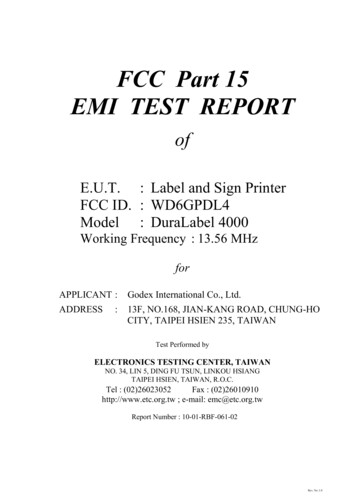
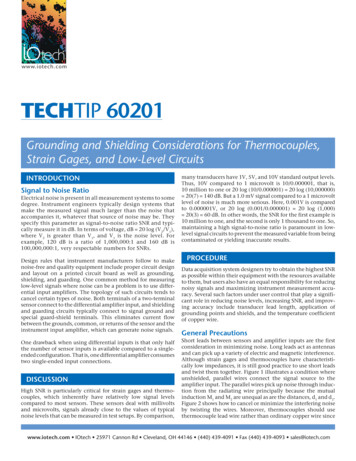
EiEtJoCurrent onfront wall dueto reflectionfrom rear wallJtRereflectionfrom rear wallFigure 3 Variation of Current Densitywith Thickness for Electrically Thin Wallenclosure, the current distribution inthe gasket will also be the sameassuming it could perfectly fill theslot. (This is not possible due tomechanical considerations.)The flow of current through ashield including a gasket interface isillustrated in Figure 4. Electromagneticleakage through the seam can occurin two ways. First, the energy canleak through the material directly.The gasket material shown inFigure 4 is assumed to have lowerconductivity than the material in theshield. The rate of current decay,therefore, is also less in the gasket.It is apparent that more current willLines ofconstant currentσg σmMetal ShieldEiEtGasketgap exists in the seam, the flow ofcurrent will be diverted to thosepoints or areas which are in contact.A change in the direction of the flowof current alters the current distributionin the shield as well as in the gasket.A high resistance joint does notbehave much differently than openseams. It simply alters the distributionof current somewhat. A currentdistribution for a typical seam isshown in Figure 4. Lines of constantcurrent flow spaced at larger intervalsindicate less flow of current.It is important in gasket designto make the electrical properties ofthe gasket as similar to the shieldas possible, maintain a high degreeof electrical conductivity at theinterface, and avoid air, or highresistance gaps.Shielding andGasket Equations1The previous section was devotedto a physical understanding of thefundamental concepts of shieldingand gasketing. This section is devotedto mathematical expressions usefulfor general design purposes. It ishelpful to understand the criteriafor selecting the parameters of ashielded enclosure.In the previous section, it wasshown that electromagnetic wavesincident upon a discontinuity will bepartially reflected, and partly transmitted across the boundary and intothe material. The effectiveness of theshield is the sum total of these twoeffects, plus a correction factor toaccount for reflections from the backsurfaces of the shield. The overallexpression for shielding effectivenessis written as:Figure 4 Lines of Constant CurrentS.E. R A B(1)Flow Through a Gasketed Seamwhereappear on the far side of the shield.This increased flow causes a largerleakage field to appear on the farside of the shield. Second, leakagecan occur at the interface betweenthe gasket and the shield. If an airS.E. is the shielding effectiveness2 expressed in dB,R is the reflection factor expressed in dB,A is the absorption term expressed in dB, andB is the correction factor due to reflections fromthe far boundary expressed in dB.References1. Much of the analysis discussed in this section was performed by Robert B. Cowdell, as published in“Nomograms Simplify Calculations of Magnetic Shielding Effectiveness” EDN, page 44, September 1, 1972.The reflection term is largelydependent upon the relativemismatch between the incomingwave and the surface impedance ofthe shield. Reflection terms for allwave types have been worked outby others.3 The equations for thethree principal fields are given bythe expressions:Gf 3µr12RE 353.6 10 log10(RH 20 log10 0.462r1(2) Gf 0.136r fGµ 0.354) (3)µ16RP 108.2 10 log10 G x 10µf(4)whereRE, RH, and RP are the reflection terms for theelectric, magnetic, and plane wave fieldsexpressed in dB.G is the relative conductivity referred tocopper,f is the frequency in Hz,µ is the relative permeability referred tofree space,r1 is the distance from the source to theshield in inches.The absorption term A is thesame for all three waves and isgiven by the expression:A 3.338 x 10– 3 x t µfG(5)whereA is the absorption or penetration lossexpressed in dB, and t is the thicknessof the shield in mils.The factor B can be mathematicallypositive or negative (in practice it isalways negative), and becomesinsignificant when A 6 dB. It isusually only important when metalsare thin, and at low frequencies (i.e.,below approximately 20 kHz).(6)B (in dB) 20 log 101–((K – 1) 2(K 1) 2) (10 ) (e )–A/10–j.227AwhereA absorption losses (dB) K Z S /Z H 1.3(µ/fr 2G)1/ 2Z S shield impedanceZ H impedance of the incidentmagnetic field2. Shielding Effectiveness is used in lieu of absorption because part of the shielding effect is caused byreflection from the shield, and as such is not an absorption type loss.3. Vasaka, G.J., Theory, Design and Engineering Evaluation of Radio-Frequency Shielded Rooms,U.S. Naval Development Center, Johnsville, Pa., Report NADC-EL-54129, dated 13 August, 1956.US Headquarters TEL (1) 781-935-4850 FAX (1) 781-933-4318 www.chomerics.comEurope TEL (44) 1628 404000 FAX (44) 1628 404090Asia Pacific TEL (852) 2 428 8008 FAX (852) 2 423 8253South America TEL (55) 11 3917 1099 FAX (55) 11 3917 0817193
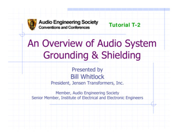
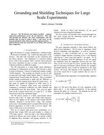
continuedThe preceding equation wassolved in two parts. A digital computerwas programmed to solve for B witha preselected value of A, while K varied between 10 –4 and 10 3. Theresults are plotted in Figure 9.The nomograph shown in Figure8 was designed to solve for K inequation (6). Note that when ZHbecomes much smaller than ZS(K 1), large positive values of B mayresult. These produce very large andunrealistic computed values of S.E.,and imply a low frequency limitationon the B equation. In practical cases,absorption losses (A) must be calculated before B can be obtained.1A plot of reflection and absorptionloss for copper and steel is shown inFigure 5. This illustration gives agood physical representation of thebehavior of the component parts ofan electromagnetic wave. It alsoillustrates why it is so much moredifficult to shield magnetic fieldsthan electric fields or plane waves.Note: In Figure 5, copper offers moreshielding effectiveness than steel inall cases except for absorption loss.This is due to the high permeabilityof iron. These shielding numbers aretheoretical, hence they are very high(and unrealistic) practical values.If magnetic shielding is required,particularly at frequencies below14 kHz, it is customary to neglect allterms in equation (1) except theabsorption term A. Measurements ofnumerous shielded enclosures bearsthis out. Conversely, if only electricfield, or plane wave protection isrequired, reflection is the importantfactor to consider in the design.The effects of junction geometry,contact resistance, applied forceand other factors which affectgasket performance are discussedin the design section which follows.Polarization EffectsCurrents induced in a shield flowessentially in the same direction asthe electric field component of theinducing wave. For example, if theelectric component of a wave isvertical, it is known as a verticallypolarized wave, and it will cause acurrent to flow in the300CopperSee text details and correction for thin sheetsshield in a verticalShielding effectiveness absorption reflection lossIronCopperAbsorptionlosspermildirection. A gasket12σ 1thicknessµ 1250placed transverse to34 Reflection loss – Electric fieldsIron3σ .17the flow of current isµ 20056 Reflection loss – Plane wavesless effective than20078 Reflection loss – Magnetic fields4one placed parallelto the flow of current.150A circularly5polarized wave6contains equal100vertical andhorizontal compo75082nents, so gaskets1must be equally0effective in both100Hz1kHz10kHz100kHz1M Hz10MHz100MHz1GHz10GHzdirections. WhereFREQUENCYpolarization isFigure 5 Shielding Effectiveness of Metal Barriersunknown, gasketedjunctions must be designedSome care must be exercisedand tested for the worse condition;in using these charts forthat is, where the flow of current isferrous materials because µparallel to the gasket seam.varies with magnetizing force.LOSS (dB)EMI Shielding TheoryNomographsThe nomographs presented inFigures 6 through 9 will aid thedesigner in determining absorptionand magnetic field reflection lossesdirectly1. These nomographs arebased on the equations describedin the previous section.Absorption Loss – Figure 6:Given a desired amount of absorptionloss at a known
It is important in gasket design to make the electrical properties of the gasket as similar to the shield as possible, maintain a high degree of electrical