Transcription
120-21 September 2018, BULGARIAProceedings of the International Conference onInformation Technologies (InfoTech-2014)20-21 September 2018, BulgariaINRUSH CURRENT INTERFERENCE BETWEEN POWERTRANSFORMERSMihail Digalovski, Goran RafajlovskiUniversity St. “Cyril and Methodius”, SkopjeFaculty of Electrical Engineering and Information Technologiesmihaild@feit.ukim.edu.mk,Republic of MacedoniaAbstract: In this paper the transient analysis of the inrush current of parallel connectedpower transformer is investigated. The MATLAB-Simulink simulation model isdeveloped for the purpose of mathematical validation.Key words: sympathetic interaction, simulation model, power transformers, inrushcurrent, MATLAB/Simulink1. INTRODUCTIONWhen calculating the transient switch-on current, it is usually assumed that thetransformer is switched on in a power system in which there are no othertransformers. In practice, this situation is almost impossible, i.e. at least onetransformer is already connected to the moment when the next transformer isconnected.In the systems with significant serial resistances, such as long transmissionlines, the above situation can lead to transient interaction between transformer that isswitched on at the moment and those already connected.The connection of large power transformers can lead to incorrect operation ofthe differential protection of the other transformers in the system. This is due to thesaturation of the already connected transformers as a result of the unexpected voltagedrop in the system [3]. The saturation of the remaining transformers is also observedin systems where the transformers are directly connected to synchronous machines,as a result of the overvoltage induced by the response of the automatic voltageregulator to the synchronous generator.
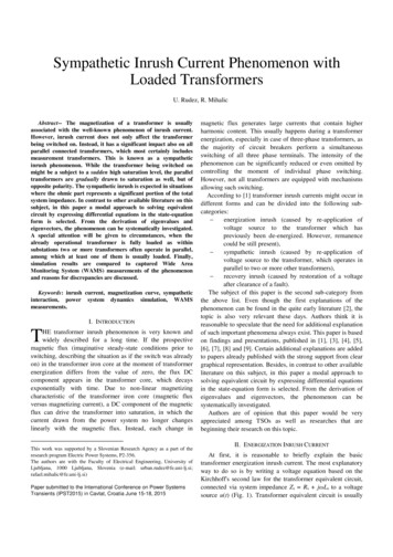
2PROCEEDINGS of the International Conference InfoTech-2018Inrush current impactIt is known that the switching on transient magnetizing current of onetransformer is a consequence of the saturation of the transformer core. This dccurrent, grows sharply to its peak value in the first half-period after the transformerhas been switched on, and then decreases to its normal stationary value in subsequentperiods.In general, the amplitude and duration of the transient current depends on: The moment of switching on, i.e. the instantaneous value of the supply voltageat the moment of switching on the transformer The magnetizing flux maximum value in the transformer core (remanentmagnetizing flux) and its direction The saturation of the magnetic core The total impedance of the inrush current circuitAll this applies if only one transformer participates in a transient phenomenon,ie, for the case when the first transformer is switched on in the system [2]. In caseswhere there are transformers in the system that are previously connected, theamplitude and duration of the initial current of the transformer which at this momentturns on can significantly deviate from the expected ones. The reason for this is thesaturation of the already connected transformers as a consequence of the inrushcurrent of switching on the newly connected transformer. This phenomenon in theliterature is known as sympathetic interaction between transformers. Therefore, inaddition to the above factors that influence to the inrush current, the next, not soinsignificant condition should be added: The level of saturation reached by the already connected transformers in thesystemThis indicates the fact that the established transient influence between thetransformer that is switched on in the system and those previously connected canextend the duration of the transient regime of switching on the transformer.Sympathetic interaction between transformersComplicated phenomenon, such as the sympathetic inrush current (transmittedsaturation), is the topic of recent research in this field.Transient magnetizing currents of high intensity do not have to flow exclusivelyin the transformer that switched on but also through the transformers that are alreadyconnected to the system. It has also been established that the transient period of thesecurrents is very long and they are decreasing much slower than the transformer'sinrush current that would be the only or first in the system.The simulation model in MATLAB / Simulink is based on the electrical schemeshown in Figure 1. It is assumed that the power system short-circuit impedance Zs inthe connection point-bus bar B1 is of high value (weak network).
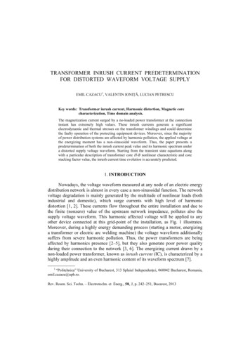
320-21 September 2018, BULGARIAS1T2S2ZsB1B2T1Fig. 1. Power system scheme for inrush current analysisThe Transformer T1 is previously connected and is in a stationary operatingregime. At a given time in parallel whit them, the transformer T2 is switched on. Asa consequence of the transient current of the T2 switching, a voltage drop of theimpedance Zs occurs decreasing the voltage of the bus bar B1. In this case, thetransformer T1 begins to be demagnetized. After several damping periods, of thecurrent flowing through power transformer T2, the B1 voltage begins to increase,making the power transformer T1 magnetizing again. It is clear that a inrush currentoccurs in the transformer T1. This current can lead to a incorrect activation of thedifferential protection, while turning off the power supply to the consumer.2. RESEARCH OBJECTResearch object is a three-phase distribution transformer, type ETN 50-10 / 0,4,in oil performance. The nominal data of the analyzed transformer are Sn 50 kVA;U1/U2 10/0,4 kV; I1/I2 2,89/72,2 A; ukn 4 %; fn 50 Hz; p 2x2,5 %; Yzn5. Theanalyzed transformer is shown in Fig. 2, and the magnetization characteristic of thetransformer core is given in Fig. 3.Fig. 2. Distribution transformer, typeETN 50-10/0.4Fig. 3. Magnetizing characteristic of thetransformer core
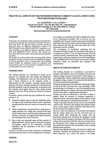
4PROCEEDINGS of the International Conference InfoTech-20183. MODEL IN MATLAB / SIMULINK FOR ANALYSIS OFSIMPATIC INTERACTION BETWEEN TRANSFORMERSThe single-pole scheme for the analysis of the phenomenon of sympatheticinteraction between two transformers is shown in Fig. 4, and the MATLAB /Simulink model is shown in Fig. 5.T1i1i2ST2Fig. 4. Connection of T2 transformer in parallel with T1 (single-pole scheme)Fig. 5. Simulation model in MATLAB / Simulink for sympathetic interaction analysis between twothree-phase transformersThe power supply of the two transformers is realized by a three-phase electricsource with its own internal impedance, which is equivalent to the power system [5].Its internal resistance represents the short-circuit impedance at the point ofconnection of the transformers (this is the busbar B1 from Fig. 1). The electricalsource generates a three-phase voltage system in the model and is tuned so that thevoltage in phase A has an initial angle of 0 degrees. The output line voltage at the
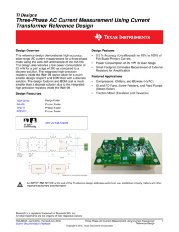
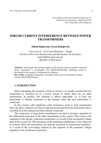
20-21 September 2018, BULGARIAsource is with an effective value of 10 kV, as much as the value of the primarywinding voltage of the transformers.Through two switches suitable for both transformers, the voltage is carried onthe primary windings. The switch-on time of the first switch is t1 0,06 (s), and of thesecond is t2 3 (s). The time of the whole simulation is set to t 10 (s). The times aretuned in this manner: first the transformer T1 must be switched on, its transientregime passes. The time when the second transformer is switched on in parallel withthe first should be long enough for the first to be entered into stationary regime.After 3 (s) from the beginning of the simulation, the second transformer is switchedon and the currents are monitored in both transformers. Also, the total time of thesimulation should be long enough for both transformers to enter the stationaryregimes and since they are identical, can compare the duration of the transientprocess when switching the network transformer on its own and in parallel with analready connected transformer. In other words, the time of the transient regime ofswitching on of the first transformer, which was independent at startup, and the timeof the transient switching regime of the second transformer, which is connected inparallel with the first one, will be compared. Calculated switching times of bothtransformers are taken in the moment when current has the greatest value, and whenthe voltage drop to zero. The residual magnetism at the core of the transformer isneglected.Phase A is taken for the reference phase to which the times are set.To measure the primary currents for each phase individually both currenttransformers are set current meters. The current signals are monitoring viaoscilloscope. Also, the three signals for the individual phase currents withmultiplexer are unified in a three-phase signal, which represents the three-phasesystem of primary currents.In the transformer blocks, all values for its data and parameters are given, suchas: nominal power, nominal primary and secondary voltage, nominal frequency,active and reactive resistance of primary and secondary windings in per units,magnetization characteristic, delta-, or way-connection, and winding vector group [1].On the secondary terminals of the transformers, voltage sensors are placed,recording the voltage measured signals. Then the multiplier signals turn into singlesizes and ultimately led into integrators that exit the flux for each phase individuallyas an integral of the corresponding phase voltage [4]. Fluxes are further implementedon oscilloscopes, which monitor their change over time.4. SIMULATION RESULTSFig. 6 shows the switching on currents of the transformer T1, and in Fig. 7 thephase fluxes, respectively for each of the phases. For the transformer T2, theswitching currents are shown in Fig. 8 and the fluxes in Fig. 9. The figures show that5
6PROCEEDINGS of the International Conference InfoTech-2018transient phenomena are most dominant in phase A, since that phase is taken as areference, respectively, and both transformers are switched on at the moment whenthe phase voltage UA passes through zero, and then the flux has a maximum value. Inthe other two phases, the amplitude of the transient inrush current is less than inphase A. If the current in phase A is considered, it can be noticed that when thetransformer T1 is switched on in no-load regime, due to the process of magnetizingthe transformer core, its amplitude reaches a value of about 70% of the nominal. Inthe simulation, the two transformers are tuned at the time of switching on to have noresidual magnetism in their magnetic circuits. If there is a residual magnetism, othertransient phenomena would occur, and the greatest amplitudes of the transientcurrents occur in the remanent magnetism with the opposite polarity from themagnetic flux that is established at the moment of connection. When the transformerT1 is connected to a network, another transformer is not connected to the terminalsand its transient process lasts about 1.5 (s). Then the transformer enters stationarymode and the effective current value is I0. At the moment t 3 (s), it switches on ofthe network at the same transformer T2, but now one transformer has already beenconnected to the network. At that moment in T2 begins the magnetization processand because it is identical to T1, the amplitudes of the inrush currents are the same.Then there is a sharp drop in the terminal voltage, because the short-circuitimpedance at that point has a great value ("weak network"). Transformer T1 has areversible process from that of T2. The T1, which is entered into the stationaryregime and its core is magnetized, in case of a sudden drop in voltage, its core beginsto be demagnetized and a transient process is called sympathetic interaction betweenthe transformers. The current that occurs in this process is called the sympatheticcurrent of the transformer T1. From Fig. 8, it is noted that the inrush current in phaseA of the transformer T2 is more difficult to dampen than in the case when T1 wasturned on, as the first transformer in the network. The transient period is much longerand lasts about 8 (s). This is due to the transient interaction of the two transformers,which are already connected in parallel. The duration and influence of thesympathetic current on the power systems i.e. the other transformers depends onvarious factors. The phenomenon is more evident in transformers with higher power,in high-impedance networks at a short circuit at the point of switching on thetransformer. Also, the appearance is more noticeable in transformers with a agedmagnetic material. An important role for the amplitude of the inrush current is thecombination of the moment of connection and the magnitude of the remnantmagnetic flux.The sympathetic saturation of the transformers is intensive at the firstelectrification of the transformer substation, especially on no-load mode of operationor at very low loads.
720-21 September 2018, BULGARIAIAIA (pu)0,20-0,2012345678910-0,4-0,6-0,8t (s)IBIB (pu)0,30,20,1001234-0,1567678910t (s)ICIC (pu)0,30,20,10-0,10123458910t (s)Fig. 6. Inrush current in the transformer Т1Flux AFlux A (pu)1,510,50-0,5 012345678910-1-1,5t (s)Flux BFlux A (pu)1,510,50-0,5 012345678910678910-1-1,5t (s)Flux CFlux C (pu)1,510,50-0,5 012345-1-1,5t (s)Fig. 7. Phase fluxes when the switching on the transformer Т1
8PROCEEDINGS of the International Conference InfoTech-2018IA (pu)IA0,80,60,40,20-0,2 012345678910t (s)IB (pu)IB0,10012345678910-0,1-0,2-0,3t (s)IC (pu)IC0,10012345678910-0,1-0,2-0,3t (s)Fig. 8. Inrush current in the transformer Т2Flux A (pu)Flux A1,510,50-0,5 012345678910678910-1-1,5t (s)Flux B (pu)Flux B1,510,50-0,5 012345-1-1,5t (s)Flux CFlux C (pu)1,510,50-0,5 012345678-1-1,5t (s)Fig. 9. Phase fluxes when the switching on the transformer Т2910
20-21 September 2018, BULGARIA5. CONCLUSIONWhen one unloaded transformer is connected to a network, the primary currentdoes not currently reach its nominal value, but this occurs after the transient period,which is characterized by a current t
Key words: sympathetic interaction, simulation model, power transformers, inrush current, MATLAB/Simulink 1. INTRODUCTION When calculating the transient switch-on current, it is usually assumed that the transformer is switched on in a power system in which there are no other transformers. In practice, this situation is almost impossible, i.e. at least one transformer is already