Transcription
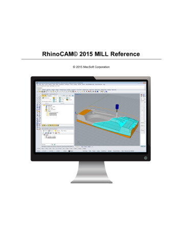
RhinoCAM 2015 MILL Reference 2015 MecSoft Corporation
2RhinoCAM 2015 MILL ReferenceTable of ContentsWelcome to RhinoCAM 2015’s MILL Module31 Overview.of MILL Module32 Features.of MILL module43 Understanding.MILL Module64 Programming.Workflow95 Post-Processing. 9User Interface101 RhinoCAM.2015 Menu Item112 RhinoCAM.2015 MILL Browsers113 RhinoCAM.2015 Machining Browser12Brow ser Toggle.Tabs13Program Tab . 13Sim ulate Tab . 164 RhinoCAM.2015 Machining Objects (MObs) Browser18Tools Tab. 19Regions Tab . 23Features Tab . 25Understanding.Hole Features in RhinoCAM 201528Hole Features.Filters Dialog30Select/Load/Create.Operations for Creating Hole Features32Select from.Matching Know ledge Bases35K-Bases Tab . 375 Docking.Browsers38Creating 3 Axis Machining Operations401 Parallel.Finishing40Cut Param eters. 43Z containm ent. 46Entry/Exit. 48Control Geom.etry51Tool. 53Feeds & Speeds. 55Clearance Plane. 59Where to go for more helpIndex620 2015 MecSoft Corporation
Welcome to RhinoCAM 2015’s MILL Module3Welcome to RhinoCAM 2015’s MILL ModuleThe RhinoCAM 2015 MILL module offers fast gouge free solids/surface model machiningtechnology coupled with cutting simulation/verification capabilities running inside Rhino. Thisintegration allows for seamless generation of toolpath and cut material simulation/verificationinside Rhino, for programming milling machines that support 3, 4 and 5 axis continuousmachining. The MILL module also comes with numerous post-processors to output theprogrammed G-code to some of the most popular machines in the market. A simple and wellthought out user interface makes this system one of the most intuitive and easy to use millingsystems on the market. This online help system provides comprehensive help topics as wellas context sensitive help to help you become a productive user of RhinoCAM 2015.Related TopicsOverview of MILL ModuleFeatures of MILL moduleUnderstanding MILL ModuleProgramming Work-flowPost-ProcessingC opyright 2015/2016 MecSoft C orporationMonday, August 31, 20151.1Overview of MILL ModuleThe RhinoCAM 2015 MILL module offers fast gouge free solids/surface model machiningtechnology coupled with cutting simulation/verification capabilities running on standardWindows hardware. These features take the uncertainty out of the toolpath programmingprocess and allow you to produce toolpaths that you can send to the machine tool withutmost confidence. A simple and well thought out user interface makes this system one of themost intuitive and easy to use milling systems in the market. This feature makes RhinoCAMsuitable to be deployed in the shop floor to work in conjunction with your existing CAD/CAMsystem.The RhinoCAM 2015 MILL module supports milling operations from simple 2 ½ axis milling tocomplex 3 axis milling. Additionally drilling operations are supported in three axis mode. Mostof the popular machine tool controllers are supported out of the box. Additionally theRhinoCAM 2015 MILL module also includes a post-processor generator product that can beused to tailor the output to virtually any machine tool controller in the market.Related TopicsWelcome to RhinoCAM 2015’s MILL Module 2015 MecSoft Corporation
41.2RhinoCAM 2015 MILL ReferenceFeatures of MILL moduleThe list below summarizes the toolpath generation features found in MILL module.Data Import:Supports file formats that can be imported in Rhinoceros 5.0.2 ½ Axis Methods:Face Milling, Pocket Milling, High Speed Pocketing, Profile Milling, V-Carve Roughing,V-Carving, Engraving, Chamfering, Hole Pocketing, Hole Profiling, Thread Milling andT-Slotting**Hole Feature DetectionFull and Partial Hole Features can be detected automatically and managed forDrilling operations.2 ½ Axis Advanced Methods:Re-machining3 Axis Rough Milling Methods:Horizontal Rough Milling3 Axis Finish Milling Methods:Parallel Finish Milling and Horizontal Finish MillingCurve Based Finishing Methods:Radial Milling, Spiral Milling3 Axis Advanced Roughing Methods:Plunge Roughing, Horizontal Re-Roughing, Plunge Re-Roughing3 Axis Advanced Finishing Methods:Clear Flat Tops, Projection Pocketing, 3D Offset Pocketing, 3D Offset Profiling,Reverse Post Milling, Steeps Machining (Parallel Hill), Steeps Z Finishing (HorizontalHill), Plateau Milling, Curve Profile Milling, Between 2 Curves Machining3 Axis Re-Finishing Methods:Pencil Trace Milling, Valley Re-finishing3 Axis Machining Region Methods:Flats Regions, Steeps Regions, Silhouette Regions, Valley Regions, Check Regions, 2015 MecSoft Corporation
Welcome to RhinoCAM 2015’s MILL Module5Collision Regions4 Axis Methods:Index - Rotate Table Operation4 Axis Facing, 4 Axis Pocketing, 4 Axis Profiling4 Axis R-Level Roughing, 4 Axis R-Level Finishing, 4 Axis Finishing, 4 Axis ProjectionPocketing and 4 Axis Engraving5 Axis Methods:5 Axis Index – Using Setup and Set Work Zero Operation5 Axis Simultaneous Methods:Curve Projection, Flow Curve, Between 2 Curves, Drive Curve, Surface Normal,SwarfDrilling Methods:Drilling, Tapping, Boring, Reverse Boring4 Axis Drilling, Tapping, Boring, Reverse Boring2 ½ Axis T-Slotting is available in Expert, Professional and Premiumconfigurations.2½ Axis Advanced Methods, 3 Axis Advanced Roughing and FinishingMethods, 3 Axis Re-finishing Methods, 3 Axis Machining Region Methodsand index 5 axis Methods are available in Professional and Premiumconfigurations.4 axis methods are available in Expert, Professional and Premiumconfigurations.5 Axis Simultaneous Methods are available in Premium configuration.Multi-threading toolpath generationThis feature allows the usage of multi-cores in your computer when performingcalculations during the generation of toolpaths. This can yield performanceimprovements of an order of magnitude when compared with single threadedtoolpath generation.Tool Types:Ball End Mill, Flat End Mill, Corner Radius Mill, V Mill, Chamfer Mill, Taper End Mill, 2015 MecSoft Corporation
6RhinoCAM 2015 MILL ReferenceThread Tool, Face MILL**, Drill Tool, Center Drill Tool, Reamer, Tap Tool, Bore Tool,Reverse Bore Tool, Dove-Tail Tool**, Fillet Mill**, Lollipop Tool**, User Defined Tool**User customizable tool library:Create and save tools to library. Saves feeds and speeds to tool library.Feeds and Speeds:Customizable feeds and speeds table, Feeds and Speeds calculatorCut Material Simulation:Fast and fully integrated Material Cutting SimulationCreate true 3D in-process stock modelAdvanced cut material simulation** - includes tool holder collision and part stockcomparison.Machine Tool Simulation* - allows the graphical definition of machines andvisualization of machine motions.* Available in Professional and Premium configurations.** Available in Expert, Professional and Premium configurations.Post-Processors:Standard set of post-processors bundled with the product.Choose from our large set of standard post processors.Post-Processor Generator:Customize your Post Processor or create your own Post Processor from scratch.This post processor generator supports 3 axis posts.Related TopicsWelcome to RhinoCAM 2015’s MILL Module1.3Understanding MILL ModuleThe manufacturing process aims to successively reduce material from the stock model untilit reaches the final shape of the designed part model. To accomplish this, the machinist orprogrammer utilizes a machining strategy.Roughing Operations 2015 MecSoft Corporation
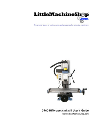
Welcome to RhinoCAM 2015’s MILL Module7A typical machining strategy employed in the manufacturing industry is to use largercutters to perform bulk removal of material early on in the manufacturing process.These operations are called roughing operations.Pre-Finishing OperationsThis is then followed by operations employing successively smaller cutters removingproportionately smaller amounts of material from the stock model. This is done untilthe part has a uniform amount of stock left. These operations are called pre-finishingoperations.Finishing OperationsThis is then followed by finish operations. Here the uniform stock remaining on thepart is removed by using a small cutter removing a constant amount of material withevery motion to produce the net shape.Standard MILL Module Work-flowThe standard work-flow of MILL module mimics this process and can be representedby the flow chart shown below.The w ork-flow of the MILL m odule m im ics the standard production process ofm aterial rem ovalPart Geometry 2015 MecSoft Corporation
8RhinoCAM 2015 MILL ReferencePart geometry is imported into the RhinoCAM 2015 MILL module via the various datainterfaces provided in Rhino. A stock model representing the raw stock from whichthe part needs to be manufactured can then either be created using the various toolsprovided in the MILL module or imported.Typical Machining StrategyYou then determine the machining strategy to be used in manufacturing the part.This can be done by loading a previously saved manufacturing operation sequenceor by creating a new one. This manufacturing strategy is represented by a sequenceof machining operations in the MILL module.To create a new machining strategy, simply select the tools and the machiningoperations in sequence and then generate toolpaths. The system automaticallyrecords this sequence. This record can be archived as an operation list that can beretrieved for later use.Here is a typical machining strategy:1. To create a new machining operation, select a tool followed by the type oftoolpath to be created. You set the parameters to use for machining andgenerate the toolpath.2. A 3D part is typically machined using 3 axis operations. It can be roughmachined initially by employing a horizontal roughing operation, followed by afinishing operation. The horizontal roughing toolpath will typically be generatedusing a relatively large flat end mill or an end mill with a corner radius toefficiently remove bulk of the material from the raw stock. This machiningoperation could be followed up with another horizontal roughing operationeither with the same tool or with a smaller tool to remove more material.3. The part can then be pre-finished by employing either the parallel finishingoperation or the horizontal finishing operation. Pre-finishing and finishingoperations typically employ ball end mills with or without a side angle.4. Finally a parallel finishing operation using a small radius ball tool andemploying a fine step-over is then used to finish the part to net-shape. Thismay or may not be followed by other re-finishing operations to reducehandwork on the part.For Prismatic PartsFor prismatic parts that have straight walls, it might be more expedient to use 2-1/2axis toolpath methods rather than the 3 axis methods described above. The strategyfollowed however will be similar where in bulk material removal or roughing will beperformed by a combination of facing and pocketing operations. These will then befollowed up with one or more profile finishing operations. It should be noted that for2-1/2 axis operations it is not necessary to have the complete 3D geometry defined.Curves that represent the sides of the part are sufficient to define the geometry formachining.Review, Manage and Post Process 2015 MecSoft Corporation
Welcome to RhinoCAM 2015’s MILL Module9Once all of the operations are completed you can then go back and review theoperation sequence, perform Tool and Cut Material Removal Simulations, re-orderoperations if desired and output the toolpath for post-processing. The MachiningBrowser can be used to manage these operations.Related TopicsWelcome to RhinoCAM 2015’s MILL Module1.4Programming WorkflowOnce the part is loaded, the typical work-flow is reflected in the layout of the tabs of theMachining Operations (MOps) Browser window. The work-flow is designed to allow you towork starting from the left most tab and ending at the right most tab. As each tab isaccessed, a ribbon toolbar with functions specific to the tab chosen will be displayed justbelow the tab. The functions in each of the toolbars corresponding to each tab are also bestaccessed in order from left to right.Thus you typically would start with the Program tab and access each of the buttons,optionally, in the toolbar that appears when this tab is selected in sequence from left to right.Once the setup functions are completed, you will then proceed to the Machining Operationsgroup to commence programming the part. Once machining operations are completed youcan simulate the operations by selecting the Simulate tab before finally sending the operationcodes to the machine tool.Step 1: Program TabStep 2: Simulate TabRelated TopicsWelcome to RhinoCAM 2015’s MILL Module1.5Post-ProcessingOnce the machining operations have been created and verified, they can be post processedto create G-code files. These G-code files can then be sent to the controller of the machinetool to drive the actual machine tool.Related TopicsWelcome to RhinoCAM 2015’s MILL Module 2015 MecSoft Corporation
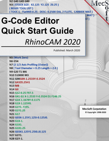
10RhinoCAM 2015 MILL ReferenceUser InterfaceMILL module adheres to the Windows standard for user interface design and integrated intothe Rhino screen seamlessly.MILL Module DisplayedA screen shot of MILL module running inside of Rhino is shown below:A screen shot of MILL m odule running inside of RhinoMILL Modules 3 Interface ObjectsThere are 3 main interface objects created when MILL module is loaded.1. RhinoCAM menu bar entry under Rhino menu bar2. Machining Browser (MOps) window3. Machining Objects (MObs) Browser windowRelated TopicsRhinoCAM 2015 Menu ItemRhinoCAM 2015 MILL BrowsersRhinoCAM 2015 Machining Browser 2015 MecSoft Corporation
User Interface11RhinoCAM 2015 Machining Objects (MObs) BrowserDocking Browsers2.1RhinoCAM 2015 Menu ItemWhen RhinoCAM is loaded it will add a menu bar item, titled RhinoCAM 2015 to the mainRhino menu bar. Selecting this menu bar item will create a drop down menu as shownbelow.RhinoCAM m enu ItemTo run the MILL module, select MILL from the RhinoCAM 2015 drop down menu.Selecting MILL toggles the display of the Milling Browser window from the Rhino userinterface . If FreeMILL, Turning, Nesting or Art Browser is currently open selecting this willswitch to Milling browser.Related TopicsUser Interface2.2RhinoCAM 2015 MILL BrowsersThe Browser is a dock-able window that allows management of various entities or objectsthat can be created in MILL module. There are 2 browsers in RhinoCAM – MachiningOperations Browser (MOps) and Machining Objects Browser (MObs). 2015 MecSoft Corporation
12RhinoCAM 2015 MILL ReferenceRelated TopicsUser Interface2.3RhinoCAM 2015 Machining BrowserThe Machining Browser, sometimes called the Machining Operations (MOps) Browser, hastwo main modes of operation represented by tabs at the top of the window. These areProgram and Simulate. Each tabbed view also incorporates a ribbon toolbar at the top.These toolbars group all of the functions associated with the type of object in the tab.The Machining Operations (MOps) BrowserThe Machining Operations (MOps) Brow serRelated TopicsUser InterfaceBrowser Toggle TabsProgram tabSimulate tab 2015 MecSoft Corporation
User Interface2.3.113Browser Toggle TabsTabs available on the Machining Browser that allow you to toggle the display of both theMachining Browser and the Machining Objects Browser.Browser Toggle TabsLocating the Brow ser Toggle TabsSelecting this tab toggles between the MILL and the TURNMachining Browser.Select this tab to toggle the display of the Machining ObjectsBrowser.Related TopicsRhinoCAM 2015 Machining Browser2.3.2Program TabSelecting the Program tab in the MOps Browser provides access for specifying Machine,Stock and the definition of Machining Operations.The Machining Operations (MOps) Browser, Program Tab 2015 MecSoft Corporation
14RhinoCAM 2015 MILL ReferenceThe Machining Operations (MOps) Brow ser, Program TabMachine Setup PaneMachine Tool Setup: Sets the Machine for 2 ½ axis, 3 axis, 4 axis and5 axis operations.Set Post-Processor Options: Allows you to set the Current PostProcessor, posted file naming conventions, posted file extension,program to display the posted file.Create Setup Operations: Sets the Coordinate System for Machining.The orientation of the part can be set using Orient Part, orientation ofthe Coordinate System can be defined under Set CSYS Setup for 3 2 machining and Rotate Table Setup for 4 axis table rotateoperations.Stock PaneCreate Stock Model: Allows you to create Stock geometry. User canalso delete a Stock geometry by selecting Delete Stock.Align: Allows you to Align stock model to part and locate WCS with 2015 MecSoft Corporation
User Interface15respect to Part or Stock . This function is especially useful when thepart model and the stock model are created without regard to theirrespective positional locations.Define Stock Material: Allows you to select a material from thematerial list.Machining Operations PaneThis section allows you to create machining operations. MILL module allows youto create multiple machining operations in a part file. This is a powerful featurethat allows you to create an entire sequence of machining operations that isnecessary to create the part model from the stock model. This set of operationscan additionally be archived with the part file and retrieved at a later time with noloss of information.Set Current Work Coordinate Zero: Allows you to set the workCoordinate zero (Origin) for the part being programmed.Create 2 ½ Axis Milling Operations: Provides access to 2 ½ AxisMachining MethodsCreate 3 Axis Milling Operations: Provides access to 3 Axis Machiningor MethodsCreate 4 Axis Milling Operations: Provides access to 4 Axis MachiningMethodsCreate 5 Axis Milling Operations: Provides access to 5 Axis MachiningMethodsHoles: Provides access to Drilling, Tapping, Boring and Reverse BoringMachining MethodsCreate Miscellaneous Operations: Allows you to create MachiningOperation Sets, Machine Control Cycles, Fixture Offset and XY Instanceoperations.Knowledge Base Operations: Allows saving and loading of Machiningoperations to and from a knowledge base.Set CAM Preferences: Provides access to specify Color, User Interface,Machining, Simulation and Feeds Speeds Preferences.Utilities: Provides access to G Code Editor and Post Process Generator. 2015 MecSoft Corporation
16RhinoCAM 2015 MILL ReferenceSet Ribbon Preferences: Allows you to select a display theme for theribbon bar in the MOps Browser.Minimize/Maximize Ribbon bar: Minimizes & Maximizes the ribbon bar.Display Help Content: Open On-line Help document.The Status bar on the Program tabThe toolbar above status bar on the Program tab has the following controlsStock Model Visibility: Turn on/off stock modelMaterial Texture Visibility: Turn on/off material texture visibilityToolpath Visibility: Turn on/off toolpath displayDisplay Toolpath Levels: Displays tool path by Z levelsWorld CSYS Visibility: Turns on/off of World Coordinate Systemdisplay.Machine CSYS Visibility: Turns on/off of Machine CoordinateSystem display.The status bar displays the currently selected tool, spindle speed and cutfeedrate.Related TopicsRhinoCAM 2015 Machining Browser2.3.3Simulate TabSelecting the Simulate tab allows you to run the material simulation and toolpath animation.This tab also provides controls to vary simulation speed and set simulation preferences.The Machining Operations (MOps) Browser, Simulate Tab 2015 MecSoft Corporation
User Interface17The Machining Operations (MOps) Brow ser, Sim ulate TabSimulate Tab FunctionsThe following controls are available on the Simulate tab:Create Stock Model: Allows you to create Stock geometry.User can also delete a Stock geometry by selecting DeleteStock.Perform Toolpath Simulation or Animation: Allows you toperform cut material simulation with tool animation.Simulate Next Toolpath Block: Simulation is performed in stepsas defined by the display interval in the simulation preferences.Simulate Next Toolpath Z Levels: Simulation is performed inseparate Z levels.Simulate to End: Simulation is performed without updating thedisplay until the end of the toolpath.Pause Toolpath Simulation: Pause/Stop the simulation.Part Stock Compare*: Compare the simulated model with thepart geometry. The part geometry must contain surface/solid/ 2015 MecSoft Corporation
18RhinoCAM 2015 MILL Referencemesh geometry.Stop Toolpath Simulation: Exits Simulation Mode. Pausesimulation before exiting simulation mode.Simulation Speed: Varies simulation speedSet Simulation Preferences: Provides access to simulationpreferences.Simulate by Moves: Switches from Simulate by Distance toSimulate by Motions.The toolbar above status bar on the stock tab had the followingcontrols in addition to the controls listed under the Program tab.Part Model Visibility: Turn on/off part model display duringsimulation.Tool Visibility: Turn on/off tool display during simulation.Holder Visibility: Turn on/off tool holder display during simulationMachine Tool Visibility**: Turn on/off machine tool displayduring simulationThe status bar displays the progress of the operation currentlybeing simulated and number of Goto motions.Notes* Available in Expert, Professional and Premium configurations.** Available in Professional and Premium configurations.Related TopicsRhinoCAM 2015 Machining Browser2.4RhinoCAM 2015 Machining Objects (MObs) BrowserThe Machining Objects (MObs) browser has two main modes of operation represented bytabs at the top of the window. These are Tools and K-Bases. Each tabbed view alsoincorporates a toolbar at the top. These toolbars group all of the functions associated with the 2015 MecSoft Corporation
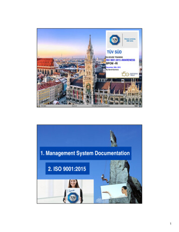
User Interface19type of object in the tab.To toggle the display the Browser select the Tools MachiningObjects button located on the Machining Browser just to the leftof the Program tab.The Machining Objects (MObs) BrowserThe Machining Objects (MObs) Brow serRelated TopicsUser InterfaceTools TabRegions TabFeatures TabK-Bases Tab2.4.1Tools TabSelecting the Tools tab under the Machining Objects Browser brings up the tool manager.The tool manager lists all of the tools currently defined as well as the tools that are in use inmachining operations. Users can edit a tool by double clicking the tool button in the browser.A tool can be deleted by selecting the tool from the Tools browser, right click cut or use thedelete key from the keyboard.The Machining Objects (MObs) Browser, Tools Tab 2015 MecSoft Corporation
20RhinoCAM 2015 MILL ReferenceThe Machining Objects (MObs) Brow ser, Tools TabRhinoCAM 2015 supports 2 types of tool library file format *.vkb and*.csv.*.vkb format saves and loads tools with the feeds and speedsassigned for each tool.*.csv format saves and loads tools without the feeds/speedsassigned for each tool.Tools Tab FunctionsCreate/Edit Tools: This button brings up the tool dialog that enables thecreation and saving of the desired tool. All milling, drilling and user definedtools can be created here. Refer to Tool section for a detailed descriptionon creating tools and defining tool parameters.Load Tool Library: The load tool library button enables the loading of apreviously saved tool library. Refer to the following section for additionalinformation - Load Tool LibrarySelect Tools from Library: The select tool library button enables you toselect tools from a previously saved tool library. Refer to the followingsection for additional information - Select Tools from LibrarySave Tool Library: This button enables the created tools to be saved in atool library file. The file can be saved in the desired directory and read inwhen required. Refer to the following section for additional information Save Tool LibraryUnload Tool Library: This button will unload the current Tool Library.List Tools: The button brings up all the tool properties associated with thetools currently recorded in the current MILL session. Refer to the followingsection for additional information - List Tools 2015 MecSoft Corporation
User Interface21Compute Tool Holder Collisions*: Determines tool holder collision with thepart geometry. Refer to the following section for additional information Compute Tool Holder CollisionsRight-click Options on ToolsYou can right-click on a Tool listed in the MObs Browser to perform variousfunctions. These are listed below:Right-click Options on a ToolEditDisplays the Create/Edit Tool dialog allowing you to edit the Toolparameters.RenameAllows you to Rename the selected tool.Cut / Copy / PasteThese options allow you to Cut or Copy the selected Tool to theWindows Clipboard and then Paste it back to the Tools list to create anew tool using the previous tool as a template.Add to LibraryThis allows you to Add the selected Tool to an exiting Tool Library *.csvdata file. 2015 MecSoft Corporation
22RhinoCAM 2015 MILL ReferencePreviewThis will display a Preview of the selected Tool in the Graphics Windowsimilar to how the Tool displays during Simulation.Tools Toolbar FunctionsSorting Selector: This allows you to sort the tool list. You can select NoSort or sort by Name, Number, Type and Diameter.Sort in Ascending/Descending Order: This icon acts like a toggle toswitch between Ascending and Descending sort order.List on the Tool used in Machining Operations: Toggle this icon to listONLY the tools currently assigned to an operation. Note: You mustGenerate an operation for the assigned tool to be listed.Tools Sorted byUsedTools Sorted by Nam eTools Status BarThe status bar displays the currently selected tool, tool tip radius& angle, spindle speed and cut feedrate.Status Bar, Tools Tab, Machining Objects Brow serNotes* Available in Professional and Premium configurations.Related TopicsRhinoCAM 2015 Machining Objects (MObs) Browser 2015 Mec
Supports file formats that can be imported in Rhinoceros 5.0. 2 ½ Axis Methods: Face Milling, Pocket Milling, High Speed Pocketing, Profile Milling, V-Carve Roughing, V-Carving, Engraving, Chamferin