Transcription
Limits, Fits and TolerancesProf. S. S. PandeMechanical Engineering DepartmentIndian Institute of Technology, Bombay1
Outline Basic Definitions ISO system for Tolerance Specification Tolerance Design for assembly- Fits Design of Limit Gages Taylor’s Principle
What is Tolerance ?Permissible variation in the size(dimension) of a component tosuit Functional Requirements
How to choose Tolerance?TimeCost Part Function Cost of Production Productivity (Time)Tolerance Availability of Manufacturing Resources
Tolerance CalloutNumeric 0.02025 0.015 0.015250.010AlphaNumeric (ISO)Hole: 25 H7Shaft: 25 g6Assembly: 25H7g625-0.010
Tolerance Zones – Shaft and HoleHoleZero lineDmaxDminShaftdmaxdmin
Basic Definitions 0.030Hole: 25.0 0.010 mmShaft/ HoleBasic SizeUpper LimitLower LimitTolerance:::::External / Internal feature of a part25.00 mm25.030 mm25.010 mmUpper limit – Lower limit 0.020 mm 20 micronsHole Designation : A, B, Z, Za, Zb, Zc – 25 NosShaft Designation : a, b, z, za, zb, zc – 25 Nos
Tolerance Zone and Limits 0.030Hole : 25 0.010Upper limitLower limitBasicTolerance 0.020 mm 20 µm25.03025.01025
Tolerance Zone Location 0.030Hole: 25.0 0.010 mmUpper Deviation : Upper limit – Basic size 0.030 mmLower Deviation : Lower limit – Basic size 0.010 mmFundamental Deviation 0.010 mmLocates Tolerance zoneBasic ShaftBasic Hole::hHFundamental Deviationis zero
ISO Tolerance Grades for Shafts and Holes
Tolerance zones - Shafts and HolesFD – Fundamental deviationADFDHZero lineHolesZPZcVpShaftsFDdavzzcZero lineh
Grades of ToleranceThere are 18 grades of tolerancesIT01, IT0, IT1 to IT16IT01 to IT4 – Gauges, measuring instrumentIT5 to IT7 – Precision Engg applicationsIT8 to IT11 – General EngineeringIT12 to IT14 – For Sheet metal workingIT15 to IT16 – Casting, General cutting work
Tolerance AllocationStandard Tolerance Unit ii 0.45 3 D 0.001D μmD (mm) : Geometric mean of the lower and upper limits of adiameter step in which the dimension lies.Diameter 0-250250-315315-400400-500
Tolerance ValuesTolerance has parabolic relationship with the size of parts.Tolerance values areIT010.3 0.008DIT00.5 0.012D--------IT6IT7IT8IT9IT10 i640i1000i100iD in mm, Tolerance in μms.
Fundamental deviations of shaftsShaft DesignationUpper Deviation(µms)a - (265 1.3D) - 3.5Dd - 16D0.44g - 2.5D0.34h Zerofor D 120for D 120D in mm15
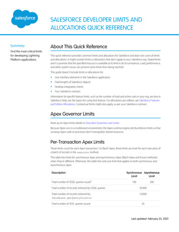
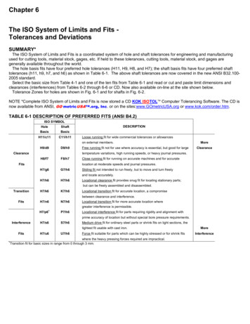
What is a Fit ? Relationship between the mating partsbefore assembly Clearance, Transition, Interference Fits Hole Basis/ Shaft Basis system
Types of Fits
Clearance Fit - Hole Basis
Transition Fit –Hole Basis
Interference Fit – Hole Basis
Typical Recommended FitsClearance FitsH7/h6 : Sealing rings, bearing coversH7/g6 : Sleeve shafts, clutchesH7/f7 : High speed bearings, machine tool spindlesTransition FitsH7/n6 : Gears and bearing bushes, shaft and wheelH7/m6 : Gears belt pulleys, couplingsInterference FitsH8/u8 : Worm wheel hubs, couplingsH7/r6 : Coupling of shaft ends, valve seats, gear wheels
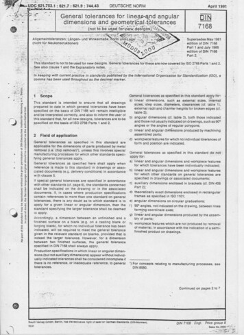
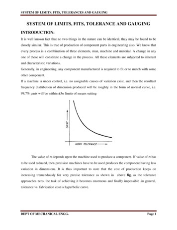
ExampleEvaluate limits and fits for an assembly pair 6 H7/ g6 mmSolution:The size 6 mm lies in the diameter step of 3-6.The Fundamental tolerance unit is 0.7327 μmTolerance for hole H7Tolerance 16i 12 μmThe fundamental deviation H hole ZeroTolerance for g6 shaftTolerance 10i 8 μmThe fundamental deviation for g shaft -2.5 D0.34 - 4 μm
Tolerance Diagram 6 H7 g66.01212 mH7 Hole6.0004 m5.9965.988g6 ShaftZero line8 mFitMaximum clearance Maximum size of hole - Minimum size of shaft Minimum clearance6.012 – 6.988 0.024 mm 24 μm Minimum size of hole - Maximum size of shaft 6.000 - 6.996 0.004 mm 4 μmThe type of fit is Clearance.
Go-NoGo Limit GagesObjective Check if the part size is within the Upper andLower size Limits Go gage should always go (into the part). NoGo gage should NOT go. Go gage should check both part Form andDimension.
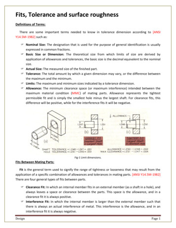
Types of Limit GagesHolePlug GageShaftRing Gage25
Taylor’s Principle for Gage DesignGo gage size corresponds to the MaximumMaterial Condition (MMC) of the Part. Upper size limit for Shaft Lower size limit for Hole
Plug Gages : Go – NoGo
Plug Gages : Go – NoGo
Gage Tolerances – Plug Gages
Ring Gages : Go – NoGo
Ring Gages : Go – NoGo
Evaluate limits and fits for an assembly pair 6 H7/ g6 mm Solution: The size 6 mm lies in the diameter step of 3-6. The Fundamental tolerance unit is 0.7327 μm Tolerance for hole H7 Tolerance 16i 12 μm The fundamental deviation H hole Ze