Transcription
The premier source of tooling, parts, and accessories for bench top machinists.3960 HiTorque Mini Mill User’s Guidefrom LittleMachineShop.com
Copyright 2012 LittleMachineShop.comAll rights reserved.Photos Copyright 2012 PhotoBoost.comAll rights reserved.Written by Chris Wood of LittleMachineShop.com.Revision .com396 W. Washington Blvd. #500, Pasadena, CA 91103(800) 981-9663 Fax (626) 797-79342
ContentsIntroduction .5Specifications .5Safety Considerations .5General Safety.5Milling Machine Safety .6Electrical Safety.6Machine Safety .6Features .8Basic Accessories.8Cleaning .9Assembly .9Mounting Your Mill . 10Operating Controls . 11Motor Controls . 11X-Axis Hand Wheel . 12X-Axis Lock Lever . 12Y-Axis Hand Wheel . 12Y-Axis Lock Lever . 12Z-Axis Coarse Feed Handles . 13Z-Axis Fine Feed Knob . 13Z-Axis Lock Lever . 13Adjustments . 14X-Axis Gib . 14Y-Axis Gib . 14Z-Axis Gib . 15Tramming the Mill . 15Lubrication. 17Maintenance . 18Cleaning . 18Changing Spindle Tools . 18Squaring a Vise . 19Using Parallels . 20Clamping with a Clamping Kit . 20Finding the Edge of a Workpiece . 21Drilling. 22Milling . 233
Conventional Milling Versus Climb Milling . 24Plunge Milling . 24Milling Slots . 25Surfacing . 25Common Accessories . 25End Mills . 25Work Holding . 26Vises . 26Clamping Kits and Accessories . 27Setup Tools . 28Parts Diagram . 29Parts List . 30Wiring Diagram . 324
IntroductionThis user’s guide covers operation and care of the LittleMachineShop.comHiTorque Mini Mill. Be sure to read and understand the safety guidelinespresented in this book before using your HiTorque Mini Mill.SpecificationsEnd Milling Capacity0.6" (16 mm)Face Milling Capacity1.2" (30 mm)Drilling Capacity0.5" (13 mm)Table Size18.1" x 4.7" (460 mm x 120 mm)T-slots3 slots 0.47" (12.0 mm) wideX-Axis Travel11.8" (300 mm)Y-Axis Travel5.1" (130 mm)Z-Axis Travel9.8" (250 mm)Throat6.5" (165 mm)X- and Y-Axis Feed Screws0.0625" (1.59 mm) per rotationPositioning Accuracy0.0004" (0.010 mm)Spindle TaperR8Spindle Motor0.67 hp (500 Watts)Spindle Speed100 - 2500 RPMPower Requirements120 V 60 Hz 8 AmpsMachine Weight124 lbs (57 kg)Overall Dimensions (W x D x H) 23.2" x 19.7" x 29.1" (590 mm x 500 mm x 740 mm)Safety ConsiderationsAlways use common sense when using a power tool. Review the followingsafety instructions. Besides the general safety rules for any power tool, thefollowing include specific considerations for the mini mill.General Safety Use common sense. Think through the results of your actions before youact.Understand the operation of the machine. Do not operate the machine ifyou do not know what is going to happen.5
Learn, don't experiment. Study, understand, and do things where you havea clear expectation of the outcome. Don't “see what will happen.”You are responsible for your own actions. We can't be held responsible foryour actions when you use the machine.Milling Machine Safety Your mini mill is just that, a mini, or small mill. Don’t attempt jobs that arebeyond its capacity.Check the workpiece after you secure it in the vise or other work holdingdevice. Be sure it is secure before turning on the mill.Don’t wear loose clothing or jewelry when operating the mill.Stop the spindle and make sure the machine is in a safe condition before:o Opening or removing safety shieldso Reaching into work areao Changing or adjusting toolso Changing or adjusting workpieceso Changing speed rangeso Clearing chips or coolantInspect cutting tools for sharpness, chips, and cracks before each use.Replace dull, chipped, or cracked cutting tools immediately.Handle cutting tools with care. Cutting edges are very sharp and can causelacerations.Do not use unbalanced tools or fixtures in the spindleRemove all tools (wrenches, chuck keys, locking pins, and so on) from thespindle immediately after using them.Electrical Safety Plug the machine into a grounded, ground fault protected receptacle.Ensure that all components are properly grounded. The easiest way toensure this is to plug your machines and devices into grounded outlets thatyou have tested.Use caution when using liquids and electricity. Ensure that coolants andlubricants are kept away from high voltage electrical components.Disconnect all components from the power receptacle before servicing.In the event of a power outage, turn off all components to ensure that themachine does not restart unexpectedly.Machine Safety Keep bystanders, children, and visitors a safe distance away while operatingany power tool.6
Read the manual. Know the operation of every control before you attemptany operation of the machine.Make sure that all guards are in place and functioning before operating themachine.Check for damage and abnormal wear before operating the machine.Always wear safety glasses (side shields are recommended) that are ANSIZ87.1-2003 compliant.Wear hearing protection (ear plugs or ear muffs) when operating loudmachines.Wear appropriate clothing; no rings, gloves, neckties, jewelry, or loosefitting garments. Bind long hair or wear a hat.Do not use compressed air for cleaning machines. A shop vacuum works welland is much safer.Don't operate machinery while under the influence of drugs or alcohol.Ensure that your machines are well lit. Ensure that your shop is well lit, andhave additional task lighting where appropriate.Maintain a clean and uncluttered work area.Avoid pinch points.Never leave a running machine unattended.Do not force or overload machinery.Use appropriate cutting tools with appropriate feeds and speed.Cutting tools get hot during use and can cause burns if handledinappropriately.Do not attempt to use workpieces that are too large or two heavy for themachine.Maintain your machines. Ensure that it is well-adjusted and in a safe state.Clear chips with a brush or other tool, never with your hands or withcompressed air.Make sure the machine is on a flat, level surface that is capable ofsupporting the weight of the machine plus fixtures, vise, and workpiece.Clamp work securely. Cutting forces are significant and can turn workpiecesthat are not secured into projectiles.Be aware that chips and dust from some materials (magnesium, forexample) are flammable. Understand the materials you are using.7
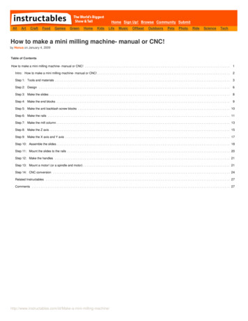
Features182910311124513614715161. Motor2. Drawbar (undercap)3. Motor controls4. Spindle5. Table6. Saddle7. Y-axis hand wheel8. Z-axis fine feedknob9. Z-axis coarse feedhandle10. Z-axis lock lever11. Column12. Z-axis travel stop13. X-axis hand wheel14. X-axis lock lever15. Y-axis lock lever16. BaseBasic AccessoriesThe following accessories come with the HiTorque Mini Mill.8
DrawbarSpindle locking pinDrill chuck arborTwo T-slot nutsOil canSpanner wrench for spindle nutHex wrenches 3, 4, 5, and 6 mmOpen end wrenches 8 x 10 mm, 14 x 17 mm, and 17 x 19 mmCleaningYour mill will arrive coated with grease to protect it from corrosion duringshipment. Follow this procedure to remove the grease:1. Wipe most of the grease off with rags or paper towels.2. Clean the surfaces with mineral spirits (paint thinner).3. Coat the surfaces with oil.See the “Lubrication” section on page 17 for specific recommendations forlubricants.AssemblyThere is only one thing to do to assemble your mill. Install the handles on theX- and Y-axis hand wheels. The handles should turn freely when installed.9
Mounting Your MillThe mini mill must be bolted down to the workbench because it is top-heavy. Itis unsafe to operate the mini mill if it is not bolted to a workbench.Before you mount your mini mill, plan the positioning carefully. If you simplybolt it to the middle of the workbench, you won’t be able to turn the Y-axishand wheel. Either mount the mini mill at the front edge of the bench so the Yaxis hand wheel hangs over the edge of the bench, or mount the mini mill on ariser about 1.5" thick to provide room to turn the Y-axis hand wheel. Themounting bolts must extend through the riser and bolt the mill to the bench tokeep it from tipping.Be sure that you have room on both sides of the mill for the X-axis travel. Thetable will move to the right so that the left end of the table is almost flushwith the saddle. You need an additional 8" to the right so that you can removethe table off the right side of the mill. The table moves to the left so that theright end of the table is almost flush with the saddle.The following diagram shows the holes required to mount the mill and the cleararea around the bolt pattern to allow use and maintenance of the mini mill.10
Mount the mill to the workbench with 3/8" or 10 mm bolts. The bolts should beabout 1" (25 mm) longer than the thickness of the workbench. Use fenderwashers on the underside of wooden benches to prevent the nuts from pullingthrough.Operating ControlsThere are several controls used to operate the mill. Become familiar with thembefore you use the mill.Motor Controls121. Power and emergency stop (E-stop) switch2. Speed controlThe red E-stop switch latches in the off position when you press the red button.To turn the switch on, press the green button.The power switch interrupts the input power to the speed control circuitboard.You control the motor speed by adjusting a potentiometer that provides thespeed setting value to the speed control circuit board.To power up the mill:1. Turn the speed control to the minimum speed position.2. Turn on the power switch by pressing the green button.Always turn the power off when you leave the mill. Leaving the power on candamage the speed control circuit board.To power down the mill:1. Turn the speed control to the minimum speed position.2. Turn off the power by pushing the red button.11
To start the mill:1. Ensure that the speed control is set to the minimum speed position.2. Advance the speed control to the desired speed.To stop the mill: Turn the speed control to the minimum speed position.X-Axis Hand WheelThe X-axis hand wheel moves the table to the left or right, depending on whichway it is turned. Use this hand wheel to position the table.The dial on this handle indicates the relative position of the table. Thegraduated dial can be repositioned for convenience. Each division of the dialrepresents a movement of 0.001".The HiTorque Mini Mill has 62.5 graduations on the dial. Each full turn of thehand wheel moves the table 0.0625" (1/16").X-Axis Lock LeverThe X-axis lock lever is on the front of the saddle behind the Y-axis handwheel. Use this lever to lock the X-axis so it does not move inadvertently.Pulling out on the lever and simultaneously turning it can change the lockedposition of this lever. Pulling out disengages the lever from the locking screwand allows it to move to a different position. You might need to adjust thescrew in the base of the lever before you can disengage the lever.Y-Axis Hand WheelThe Y-axis hand wheel moves the table to the front or back, depending onwhich way it is turned. Use this hand wheel to position the table.The dial on this handle indicates the relative position of the table. Thegraduated dial can be repositioned for convenience. Each division of the dialrepresents a movement of 0.001".The HiTorque Mini Mill has 62.5 graduations on the dial. Each full turn of thehand wheel moves the table 0.0625" (1/16").Y-Axis Lock LeverThe Y-axis lock lever is on the right side of the saddle behind the X-axis handwheel. Use this lever to lock the Y-axis so it does not move inadvertently.Pulling out on the lever and simultaneously turning it can change the lockedposition of this lever. Pulling out disengages the lever from the locking screwand allows it to move to a different position. You might need to adjust thescrew in the base of the lever to make this adjustment.12
Z-Axis Coarse Feed HandlesThe Z-axis coarse feed handles are on the right side of the spindle housing. Thethree long handles allow you to quickly lower and raise the head. Use them toposition the mill head, and also for drilling.Z-Axis Fine Feed KnobThe Z-axis fine feed knob is located on the right front corner of the spindlehousing. Use this knob to make find adjustments to the position of the headassembly.There are 60 divisions on the dial. Each full turn of the knob moves the headassembly 0.060". Each division of the dial represents a movement of 0.001".To engage the Z-axis fine feed: Move the hub and coarse feed handles in to engage the dog clutch. Youmight need to turn the Z-axis fine feed knob to align the dogs.To disengage the Z-axis fine feed: Move the hub and coarse feed handles out to disengage the dog clutch. Youmight need to turn the Z-axis fine feed knob to relieve pressure from thedogs.Fine feed disengagedFine feed engagedZ-Axis Lock LeverThe Z-axis lock lever is on the right side of the head assembly behind the Z-axiscoarse feed hub. Use this lever to lock the Z-axis so it does not moveinadvertently.Pulling out on the lever and simultaneously turning it can change the lockedposition of this lever. Pulling out disengages the lever from the locking screwand allows it to move to a different position. You might need to adjust thescrew in the base of the lever to make this adjustment.13
AdjustmentsKeeping your mini mill in adjustment is an ongoing process. You should checkall the following adjustments when you set up your mill and then periodicallyas you use your mill.X-Axis GibA gib is a strip of metal placed between the bearing surface of two machineparts to ensure a precision fit and provide adjustment for wear. The mini millhas gibs in several places, including between the saddle and the table.The X-axis gib provides adjustment for the mating dovetails on the saddle andthe table that provide the X-axis (crosswise) motion.To adjust the X-axis gib:1.2.3.4.5.6.Loosen the four lock nuts on the front of the saddle.Slightly loosen all four setscrews on the front of the saddle.Snug each setscrew equally. This will lock the table in position.Loosen each setscrew 1/8 turn to allow the table to move.While holding the setscrews from turning, tighten the lock nuts.Test by turning the hand wheel. Loosen or tighten all the setscrews thesame amount until the table moves freely, but without play in the dovetail.X-axis gib adjusting screwsY-Axis GibThe Y-axis gib provides adjustment for the mating dovetails on the base andthe saddle that provide the Y-axis (in and out) motion.To adjust the Y-axis gib:1.2.3.4.5.Loosen the two lock nuts on the right side of the saddle.Slightly loosen both setscrews on the right side of the saddle.Snug each setscrew equally. This will lock the saddle in position.Loosen each setscrew 1/8 turn to allow the saddle to move.While holding the setscrews from turning, tighten the lock nuts.14
6. Test by turning the hand wheel. Loosen or tighten both setscrews the sameamount until the saddle moves freely, but without play in the dovetail.Z-Axis GibThe Z-axis gib provides adjustment for the mating dovetails on the column andthe head assembly that provide the Z-axis (vertical) motion.To adjust the Z-axis gib:1.2.3.4.5.6.Loosen the four lock nuts on the right side of the head assembly.Slightly loosen all four setscrews on the right side of the head assembly.Snug each setscrew equally. This will lock the head assembly in position.Loosen each setscrew 1/8 turn to allow the head assembly to move.While holding the setscrews from turning, tighten the lock nuts.Test by turning the Z-axis coarse feed handles. Loosen or tighten all thesetscrews the same amount until the head assembly moves freely, butwithout play in the dovetail.Tramming the MillTramming is the process of squaring the column with the table on a mill. Itinvolves placing shims under the corners of the base of the column where itbolts to the base.Tramming the mill requires the use of a dial indicator, or better, a dial testindicator. The indicator is mounted so that it rotates with the spindle andreads against the table at the farthest distance possible from the spindle.The indicator can be mounted with a test indicator holder, or with a simpleshop-made holder.15
To tram the mill:1. Mount the dial indicator or dial test indicator so that it will rest on the frontleft and front right corners of the table.2. Take readings on the left front and right front corners of the table.Calculate the difference to see how much and which way to move thecolumn.Chris’ Tip: The factory specification is about 0.0005" per inch, or almost 0.010"over the width of the table. You may want to try to do better than this.3. Place shims under the appropriate side of the base of the column. Place theshim or shims on the side that gave you the highest reading.Place shims here4. Take additional readings, adding or removing shims. Repeat until thereadings are the same to within 0.002".5. Now mount the dial indicator or dial test indicator so that it will rest on thefront center and back center of the table.16
6. Take readings on the front and back of the table. Calculate the differenceto see how much and which way to move the column.7. Place shims under the front or back of the base of the column. Place theshim or shims on the side that gave you the highest reading.8. Take additional readings, adding or removing shims. Repeat until thereadings are the same to within 0.002".LubricationWe recommend the use of two lubricants on your mill. Where oil is required, we recommend Lubriplate 3V Machine Tool Oil.Lubriplate 3V is a 20 weight oil especially designed for machine tool waylubrication and bearing lubrication.Chris’ Tip: Lubriplate 3V Machine Oil is available from LittleMachineShop.com.If you prefer to purchase locally, get Mobil 1 synthetic motor oil, any viscosity,available at most auto parts stores. Where grease is required, we recommend Lubriplate 630-AA Lithium-BasedGrease. Lubriplate 630-AA is an NLGI No. 1 lubricant. Lithium grease is aplastic-friendly general use grease that is easy to find and easy to use.Chris’ Tip: Lubriplate 630-AA grease is available from LittleMachineShop.com,but you might have trouble finding it locally. Don’t worry about the brandname. Get white lithium grease. Every auto parts store and most hardwarestores have it.The following points on your mini mill require lubrication.LocationLubricantFrequency NotesColumn dovetailand rackLubriplate 3V MachineTool OilDailyTable and othermachined surfacesLubriplate 3V MachineTool OilDailyTable dovetailsLubriplate 630-AALithium-Based GreaseYearlyTable feed screwsand nutsLubriplate 630-AALithium-Based GreaseYearlyX-axis thrustbearingsLubriplate 3V MachineTool OilYearlyOil lubricates andprevents corrosionThe spindle and intermediate shaft bearings are deep groove ball bearings thatare shielded and do not require additional lubrication.17
MaintenanceMaintenance of the mini mill is simple, but important. Regular maintenancewill keep your mini mill working like new for many years.CleaningThe maintenance you perform most often is cleaning. Keeping swarf off ofwearing surfaces is the most important thing you can do to prolong the life ofyour mini mill. Use a 1" paintbrush to remove swarf from the machine as you work. Clean swarf from the mill, from top down after each use.Changing Spindle ToolsThe tools you work with are centered in the mini mill spindle by the R8 taper.R8 taperend millholderThe tools are held in the spindle by the drawbar. The drawbar is effectively along bolt that goes down through the spindle and retains the tool.To remove a tool from the spindle:1. Remove the plastic cap from the top of the spindle.2. Insert the spindle lock pin the hole in the side of the spindle.3. Use a wrench to loosen the drawbar about ½ turn.4. Tap the top of the drawbar with a soft-faced hammer to disengage thetaper.5. Hold the tool with one hand to prevent it from dropping, and unscrew thedrawbar. Remove the tool.18
To install a tool into the spindle:1. Put the drawbar down through the spindle from the top.2. Put the tool up into the spindle and thread the drawbar into it.3. If you have an R8 spindle, rotate the tool until the locking pin engages theslot in the side of the tool.4. Hold the tool with one hand, and tighten the drawbar with a wrench. Do notuse the spindle lock pin to tighten the drawbar, as you will make it tootight.5. Replace the plastic cap on the top of the spindle.Squaring a ViseWhen you mount a vise on the mill table, it is important that it be mountedsquare to the table. If your vise is not square to the table, you will not be ableto produce accurate work.The vise is usually mounted with the long axis of the vise perpendicular to thelong axis of the table. Thus the jaws are parallel to the X-axis of the mill.To square a vise on the table:1.2.3.4.Mount the vise on the table and snug, but don’t tighten, the mounting bolts.Open the vise jaws at least 1".Put the 3/8" diameter post on the top dovetail of a dial test indicator.Put the dial test indicator post in a drill chuck, end mill holder, or collet inthe mill’s spindle with the dial facing front.5. Move the X-, Y-, and Z-axis controls so the point of the dial test indicator isbetween the vise jaws and about 1/8" below the top of the vise jaws.6. Move the X-axis so the dial test indicator’s point is about 1/16" inside of oneend of the vise jaws.7. Move the Y-axis so that the dial test indicator’s point contacts the fixed jawof the vise. Continue moving the Y-axis to zero the dial test indicator.19
8. Move the X-axis so that the dial test indicator’s point wipes across the widthof the fixed jaw of the vise.9. Take a reading when the point of the dial test indicator reaches the far endof the vise jaw.10. Move the Z-axis to raise the dial test indicator so that the point is above thevise jaws.11. Tap the vise with a dead-blow hammer to rotate it in the appropriatedirection to reduce the reading on the dial test indicator.12. Repeat steps 5 through 11 until the reading on the dial test indicator isacceptable to you. You should be able to reduce the reading to 0.001" orless.13. Tighten the vise mounting bolts.Using ParallelsPrecision parallels are used to raise the workpiece off the bed of the vise to aposition where you can mill the top surface. Parallels come in sets of graduatedheights. Choose a pair of parallels that position the top surface of the workabove the top of the vise jaws, while keeping enough material between thejaws of the vise for effective clamping.Clamping with a Clamping KitThe clamping kit is the “Erector Set” of the milling machine. Use it to clamplarge workpieces, fixtures, and even vises to the mill table.Use 1-2-3 blocks as part of your “Erector Set.” They can be used to holdworkpieces up off the table so you won’t drill into the table. They can be usedto mount workpieces, and they can be used to set work up perpendicular to themill table.20
When clamping with step blocks and clamp bars, the end of the clamp bar onthe step block should be just a little higher than the end on the workpiece.This ensures that the end of the clamp bar makes contact with the workpiece.The stud should be located as close to the workpiece as possible so that themajority of the clamping force is exerted on the workpiece and not the stepblock.Finding the Edge of a WorkpieceOnce your work is secured on the table, the next step is to locate the edge ofthe work so you can zero the X- and Y-axis dials.Most engineering drawings show dimensions from two perpendicular edges ofthe workpiece. These are the two edges that you should “find,” or locate, asyou zero the X- and Y-axis dials.The goal is to set the X- and Y-axis dials to zero with the centerline of thespindle directly over the respective edge of the workpiece. Then allmovements of the workpiece relative to the spindle are referenced to thesetwo edges.To find the left edge of a workpiece:1. Put the solid body of an edge finder in a collet or drill chuck in the mill’sspindle.2. Offset the movable end of the edge finder so that it is not concentric withthe body.3. Move the edge finder so that it is clear of the workpiece beyond the leftedge.4. Lower the mill’s head so that the smaller diameter section of the movableend of the edge finder is next to the workpiece.21
5. Turn the mill on and adjust the speed control to about half of full speed inthe low speed range or about one third of full speed in the high speedrange.With the edge finder spinning, it is obvious that the movable end of theedge finder is not concentric with the body.6. Slowly turn the X-axis hand wheel clockwise to move the table to the left.As the workpiece approaches the edge finder it first forces the movable endto become more concentric with the body.7. When the movable end of the edge finder is almost perfectly concentricwith the body it will all of a sudden jump to one side and stay there.The point at which the movable end of the edge finder jumps to one side isthe point you are looking for. Stop turning the X-axis hand wheel at thispoint.8. Turn the motor off.9. Raise the mill’s head so that the edge finder is completely above theworkpiece.10. Set the X-axis dial to zero.11. Turn the X-axis hand wheel clockwise 0.100". Because your dial has 62.5divisions, you turn one full turn plus 37 and one half divisions.The movable end of the edge finder is 0.200" in diameter, so you are movingthe distance from the center of the edge finder to the edge of theworkpiece.12. Zero the X-axis dial.13. Note the location of the pointer relative to the X-axis scale across the frontof the table. You may want to rotate the pointer so that it aligns with oneof the tic marks on the scale.This is the zero point for your X-axis movements.DrillingThere are several ways to locate the position at which you want to drill a hole.You can use your layout tools to scribe crossed lines at the hole location, andthen use a wiggler to align the mill’s spindle over the intersection of thescribed lines.You can use an edge finder to locate two edges of the workpiece, and then usethe X- and Y-axis hand wheels and dials to locate the correct location.Once you find the location, start the hole with a center drill or spotting drill.These specialized drills have relatively large diameter shanks to preventbending or wobble as you start the hole. This ensures that the hole is locateddirectly below the center of the spindle.Next, drill a pilot hole about 1/8" in diameter (but not larger than the final si
You are responsible for your own actions. We can't be held responsible for your actions when you use the machine. Milling Machine Safety Your mini mill is just that, a mini, or small mill. Don’t attempt jobs that are beyond its capacity. Check the workpiece afte