Transcription
AN155S TEPPER M OTOR R E F E R E N C E D E S I G N1. IntroductionStepper motors are used in a wide variety ofapplications. They are prevalent in consumer officeequipment such as printers, plotters, copiers, andscanners. Stepper motors are also used in automotiveapplications for electronic throttle control, dashboardindicators, and climate control systems. Stepper motorsare also found in industrial equipment such as robotics,electronic component handlers, testers, dispensers, andother manufacturing equipment.Stepper motors are often controlled using specialfunction ICs that provide limited control functionality.Such ICs often employ a rudimentary step forward andback interface to the microprocessor that limits systemperformance. Other stepper motor systems are PC cardbased and use a host PC to provide high performancecontrol.In embedded systems it is much better to use a smallmicrocontroller to directly control the stepper motor. Avery small microcontroller such as the C8051F300 iscapable of providing a high performance motion controlsolution. The microcontroller implements a linearvelocity profile, generates the precise timing required,and outputs the stepping pattern used to drive themotor. The microcontroller directly drives the powerMOSFETs and no addition gate drive circuitry munications for remote control and distributedsystems. This reference design uses a RS232 portoperating at 57600 bps. This demonstrates thefeasibility of using serial control. It is equally feasible touse SMBus, I2C, RS485, or some more advancedUART based network protocol. The C8051F300 ishoused in a very small form factor MLP11 package,measuring only 3 mm square. The entire stepper motordrive can easily be integrated onto the back of a smallstepper motor. A system with multiple motors may use asingle small microcontroller for each motor.The C8051F300 is ideally suited for driving a steppermotor. The small form factor lends itself to integratedmotor solutions. The on chip UART and SMBus provideserial communication and control. The calibratedinternal oscillator eliminates the cost and pin-count ofusing an external crystal, while providing an accuratetime base for high speed UART and precise motorRev. 1.1 7/08timing. The low-pin count package has enough pins todrive the stepper motor and RS232 transceiver, with twoadditional I/O pins left over for special functions.This reference design demonstrates a highperformance stepper motor system using theC8051F300. The reference design provides for bothstand-alone demo operation and UART control. Thereference design may also be used as a platform forstepper motor code development using the C2D twowire on-chip debug and Flash programming interface.The reference design is complete with schematic, bill ofmaterials, printed circuit board artwork, code flowcharts,and source code. The software is also available fordownload from the Silicon Laboratories web site.2. Using the Stepper MotorReference Design2.1. Quick StartThe recommended stepper motor listed in the Bill ofMaterials is the GBM model number 42BYG205,available from Jameco Electronics . Connect the GBM42BYG205 stepper motor to the stepper motorreference design using the color code shown in Table 1.Table 1. GBM 42BYG205 Color CodeColorNameredA yellowAcommonblueA-greenB orangeBcommonbrownB-Connect the 9 V DC power supply to the 2.1 mm powerconnection on the stepper motor reference design. Plugthe power supply into 120 VAC power source. The LEDlabeled “PWR” should illuminate.Press the function switch labeled “FUNC”. The steppermotor should turn four turns. The green status LEDlabeled “STAT” should illuminate while the motor isCopyright 2008 by Silicon LaboratoriesAN155
AN155turning. Press the function switch again. The motor willrotate four turns the other direction. sPosition:0Acceleration:80 It the LED does not illuminate, check the powerconnection. If the motor does not turn, check the motorwiring.If using a stepper motor other than the GBM42BYG205, follow the color code provided with thatparticular stepper motor. Note that there is no standardcolor code for stepper motor wiring. It is best to doublecheck the wiring with a digital multi-meter. A 30 stepper motor should measure 60 from A to A- and30 from A or A- to Acommon. Phase B shouldmeasure similarly. A high impedance should beobtained when measuring from any phase A wire to anyphase B wire.The stepper motor will turn one complete rotation in 400steps. Type p4000 and then hit enter. The steppermotor will turn 10 rotations and then stop, While moving,the terminal will display the message Moving. andthe current position of the motor. The display is updatedperiodically while moving. When the move is completethe number will stop at the final position and theterminal will display the message done! and acommand prompt sign .2.2. Setting up HyperTerminal p4000Moving.Position:4000done! Connect a DB9 serial modem cable to the steppermotor reference design RS232 connector. Connect theother end to a serial port on the back of a Windows PC.Note which COM port is connected to the Stepper MotorReference Design.OpenHyperTerminalfromthestartmenu.Start Programs Accessories Communication HyperTerminal. When prompted for a new connection name,type in StepperMotor or some other descriptive name.In the next dialog box, click on the connect using pulldown menu and select the appropriate COM port (e.g.COM4). Click on OK to exit the new connection dialogbox. In the next dialog box choose 57600 bits persecond, 8 data bits, no parity, 1 stop bit, and no flowcontrol.Now hit return a few times. A prompt sign and a newline should be displayed each time the return key isdepressed. If prompt is not displayed, double-check theconnections and the serial port settings. Make sure thestepper motor board is plugged in and powered up. Toassist in debugging, test points are convenientlyprovided for the TX and RX connections on the steppermotor reference design.2.3. Command Line OperationThe command line parser understands threecommands. The commands are p for position, a foracceleration, and s for status. Each command muststart with a lowercase letter. The position andacceleration commands are followed by a numberstring.Type s and the stepper motor will display the currentposition and acceleration parameter. The text followingthe prompt sign is always user input.2Now type a120 and hit enter. The terminal will displaythe new acceleration to verify the parameter change. a120Acceleration:120 Now type p0 and hit return. The stepper motor willrotate ten turns the other direction at a slower rate.A smaller number results in a faster acceleration and afaster top speed. If you set the acceleration factor fartoo small the motor will stall at the maximum slewingspeed. If the acceleration parameter marginally toosmall, the motor will have very low torque in the slewingregion.The parser will ignore any non-numeric charactersbetween the command letter and the first number. Forexample p1000, p 1000, position 1000, and pig1000 will all be interpreted as a position 1000command. The parser does not understand capitalletters.The number parsing is terminated by the first nonnumeric character. So it doesn’t really matter what youtype after the number. It could be a carriage return,space, period, or any non-numeric character.The number parser for the position expects an unsigned16-bit integer. You can enter any position from 0 to65535. If you enter 65536, it will be interpreted as azero. The acceleration parser expects an unsigned 8-bitRev. 1.1
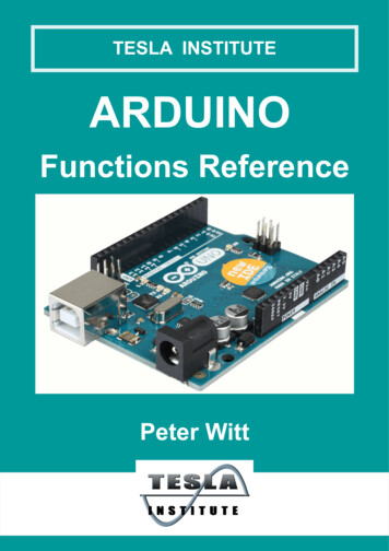
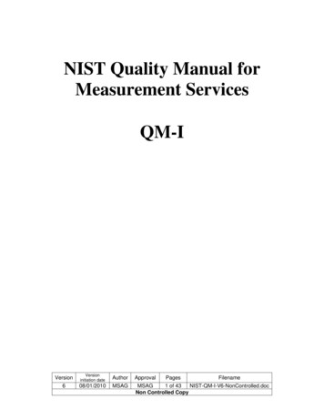
AN155integer. The range is 0 to 255. If you enter 256 it will beinterpreted as a zero. The number 257 will beinterpreted as a one. Entering a zero or a very smallinteger may produce unpredictable results.3. Theory of Operation3.1. Motor BasicsThe primary distinguishing feature of stepper motors isthe manner in which they are driven. Stepper motors aremoved in discrete steps. This is in contrast to othertypes of motors such as d.c. and brushless d.c. motorswhich are typically controlled using continuous modeanalog control methodologies. The position of a steppermotor may be expressed using an integer. The steppingrate in steps per second is typically used to describe theangular velocity.Because stepper motors are driven in discrete steps,they excel at absolute positioning applications. Themost commonly available stepper motors move inprecise increments of 1.8 or 0.9 per step.Stepper motors are controlled directly. The primarycommand and control variable is the step position. Thisis in contrast to d.c. motors where the control variable isthe motor voltage and the command variable may beeither position or velocity. A d.c. motor requires afeedback control system and controls the positionindirectly. A stepper motor system is normally operated“open loop”.using a cylindrical permanent magnet oriented with thenorth-south polarity along the rotor axis. Two laminatedend caps are used with many teeth around theperiphery. The north and south teeth are staggered toprovide many effective poles using a single permanentmagnet. The stator laminates typically have four largeforks. Each fork has many teeth. The teeth for the twowindings are also staggered to line up with theappropriate teeth on the rotor. Using this cleverarrangement, a 200-pole motor can be constructedusing a single permanent magnet and only four statorwindings.3.3. Drive TypesThe two common drive topologies for stepper motorsare unipolar and bipolar. A unipolar drive uses fourtransistors to drive the two phases of the stepper motor.The motor has two center-tapped windings with sixwires emanating from the motor as shown in Figure 1.This type of motor is sometimes rather confusinglycalled a four-phase motor. This is not an accuraterepresentation as the motor really has only two phases.A more accurate description would be a two-phase, sixwire stepper motor. A six-wire stepper motor is alsooften called a unipolar stepper motor. However, a sixwire stepper motor could be used with either a unipolaror bipolar drive. 12 V3.2. Stepper Motor ConstructionA Stepper motors may be classified by their motorconstruction, drive topology, and stepping pattern.There are several different types of stepper motorconstruction. These include variable reluctance,permanent magnet, and hybrid permanent magnet. Thisreference design is applicable to the permanent magnetand hybrid two or four phase stepper motors.Permanent magnet stepper motors are veryinexpensive and have a large stepping angle of 7.5 to18 . Permanent magnet stepper motors are often usedin inexpensive consumer products. Hybrid steppermotors are a bit more expensive and have steppingangles of 1.8 or 0.9 . Hybrid stepper motors arepredominant in industrial motion control applications.Variable reluctance motors typically have three or fivephases and require a different drive topology. Variablereluctance stepper motors are not addressed in thisreference design.The most common type of stepper motor constructionused for industrial motion control is the hybridpermanent magnet motor. The rotor is constructedAB Q1Q2Q3B–Q4Figure 1. Unipolar Stepper Motor DriveThe center tap of the motor winding is connected to thepositive voltage supply. Each coil can be energized ineither direction by turning on the appropriate transistor.The center-tapped winding acts as a transformer. So thevoltage on the unused switch will be twice the supplyvoltage.Rev. 1.13
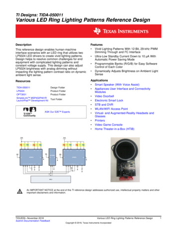
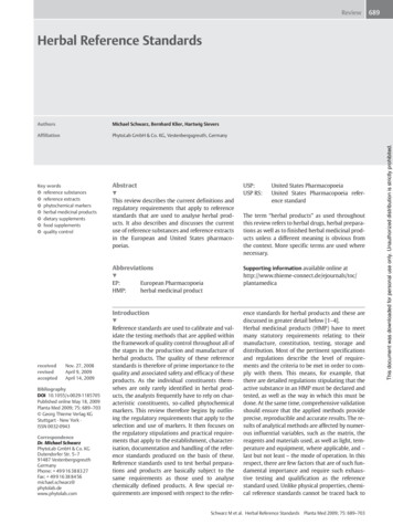
AN155A clamped unipolar drive circuit is shown in Figure 2.When Q1 is turned on, current will flow from the 12Vsupply, through the A winding, through Q1 to ground.When Q1 is turned off, the current will tend to continueto flow through the winding inductance. The drainvoltage of Q1 will rise above the supply voltage. Thecenter-tapped winding acts as a transformer. Thus,when the voltage on A reaches 24 V, the voltage onthe A- terminal will go below ground and be clamped bythe internal diode of Q2. There is also a considerableamount of uncoupled inductance in each winding. Thiswill cause an additional overshoot voltage when thetransistor is turned off. The four diodes D1-D4 and theclamp zener D5 form an effective clamp circuit to limitthe overshoot voltage. The zener voltage should beslightly higher than twice the maximum supply voltage.D1D2D3A bipolar stepper motor drive uses eight transistors todrive the two phases as shown in Figure 3. A steppermotor with four wires or six wires may be used with abipolar drive. A four-wire motor can only be used with abipolar drive. The four-wire motor might be marginallyless expensive in high volume applications. The bipolarstepper motor drive uses twice as many transistors asthe unipolar stepper motor drive. The four lowertransistors can be usually be driven directly from themicrocontroller. The upper transistors require a moreexpensive high-side drive. The bipolar drive transistorsonly need to withstand the motor supply voltage. Thebipolar drive does not require a clamp circuit like theunipolar drive.D4D5 12VA AB Q1Q2Q3B-Q4Figure 2. Unipolar Stepper Motor Drive with Zener Clamp4Rev. 1.1
AN155 VMQ1Q2Q3Q4Q5Q6Q7Q8Figure 3. Bipolar Stepper Motor DriveThe performance differences between unipolar andbipolar drives are subtle. The unipolar drive only useshalf of the actual motor windings at any one time. Thus,the bipolar stepper motor should theoretically havemuch better performance for a given motor volume. Inpractice, this is not always the case. Often the six-wirestepper motors have a lower phase resistance andconsequently a higher holding torque for a particularmotor size. The trade-offs of bipolar versus unipolar aresummarized in Table 2.7.2 for the full pattern. A full step pattern is shown inTable 3. In the full-step pattern, two transistors arealways on. The first two columns indicate whether the Aand B phase voltages are positive , negative -, or highimpedance z. The next four columns indicate the stateof the four transistors for the unipolar stepper motorshown in Figure . The last column is the state of all fourtransistors expressed in hexadecimal for use withmicrocontrollers.Table 3. Unipolar Full-Step PatternTable 2. Bipolar vs. Unipolar Trade-offsABipolarUnipolarnumber of transistors84number of high-side drivers40number of clamps04transistor voltage1 x Vs2.5 x Vswinding usage100%50%motor wires463.4. Stepping PatternsThe two possible stepping patterns for stepper motorsare full-step and half-step. A full-step pattern has fourstates and moves the motor one full step for each state.A 1.8 stepper motor will move 1.8 for each state andBQ1Q3Q2Q4Hex--00110x03- 01100x06 11000x0C -10010x09Note that the transistor order in Table 3 has beenrearranged listing Q3 before Q2 to yield a clear pattern.The polarity of the A and B windings is only important indetermining if the rotation of the motor is clockwise orcounter clockwise. Swapping the polarity of eitherphase will change the direction of the motor. SwappingA and B windings will result in no change of rotation.Table 4 is the stepping pattern for a half step steppermotor. The half step stepping pattern has eight states.Rev. 1.15
AN155Four of these states only have one transistor on at anyone time. The half-step pattern allows a positioningaccuracy of 0.9 for a 1.8 stepper motor. Note that theholding current and consequently the holding torque willbe less for the states with only one transistor on at atime.deceleration phase. The resulting angular step positioncurve n is a smooth s-shaped curve. The acceleration isconstant in the acceleration and deceleration phases.The acceleration is zero in the slewing phase. Table 4. Unipolar Half-Step - 01100x06z 01000x04 11000x0C z10000x08 -10010x09The step pattern for a bipolar stepper motor is similar.Normally the diagonally opposite transistors in each Hbridge are turned on simultaneously. Thus the stepperpattern can be readily understood by listing the uppertransistors first in the same order as the unipolar drive.Then the lower transistors are listed in the ordercorresponding to the same pattern (13246857). The endresult is that the upper and lower nibbles of thehexadecimal stepping pattern are identical.Table 5. Bipolar Full-Step PatternABQ1 Q3 Q2 Q4 Q6 Q8 Q5 Q7Hex0-000100010x11--001100110x33-0001000100x22- 011001100x660 010001000x44 110011000xCC 0100010000x88 -100110010x99 nA c c e le ra tin gC o n s ta n t-V e lo c ityFigure 4. Linear Velocity ProfileWe would like to derive a table or step periods that willbe used to commutate the motor. The step period Tn isdefined as the difference in time between two adjacentsteps in Equation 1. The step period will be used tocontrol the microcontroller timer.Equation 1.Tn tn 1 – tnThe angular acceleration is defined in Equation 2 andthe step position is defined in Equation 3. Theseequations are straightforward textbook definitions forangular velocity and position. Since the stepper motorposition moves in discrete steps the step position is aninteger denoted by the letter n instead of .Equation 2. t nEquation 3.3.5. Stepping AlgorithmA Linear-Velocity Profile is shown in Figure 4. Thevelocity ramps up and down in the shape of a trapezoid.The three distinct phases are named the accelerationphase, the constant velocity or slewing phase, and the6D e c e le ra tin gRev. 1.121n --- t n2
AN155Solving Equation 3 for time gives the results shown inEquation 4. This is the absolute time required to providea linear acceleration profile. This would be useful if wewere working in absolute time and scheduling eachcommutation point based on a cumulative count fromthe beginning. However, we would like to use a relativecount for each step period.Equation 4.tn 2n------ The definition of the step period from Equation 1 is usedwith the results in Equation 4 to provide an equation forthe step period listed in Equation 5. The constantacceleration term has been factored out and is called T0as defined in Equation 6. The value of T0 will determinethe step period of the initial step with n equal to zero.Thus, we can use a single table for the relationship andlet T0 be a variable. This means one table can be usedwith any stepper motor.Equation 5.3.6. Common MistakesAs demonstrated in the preceding section, the linearvelocity profile is not as simple as it would first appear.The values stored in the linear velocity table mustclosely follow the non-linear equation shown inEquation 5. Often engineers in a hurry to get hardwareup and running do not use the proper relation for thestepper motor table. This is a very common mistake thatis very easy to make.The most common mistake is to have the step perioddecrease linearly with the step number. For example,one might have an initial step period of 256 timer ticksand decrease the step period by one each time. Thisresults in a non-linear velocity that is increasinghyperbolically as the step period approaches zero. Sucha profile will hardly move at first and then the velocitywill increase much too quickly.The second most common mistake is to have the stepperiod decrease with the inverse of the step number.This results in a velocity that is linear with respect to thestep number. But this ignores the fact that the stepperiod is constantly changing. The velocity should beplotted against the cumulative time, not the stepnumber. If the velocity is plotted against the absolutetime, the resulting curve is a second order function. Thatis, the velocity is increasing with the square of time. Thisprofile also starts out too slow and ends up acceleratingtoo fast.3.7. Linear-Velocity vs. Linear-AccelerationTn tn 1 – tn T0 n 1 – n Equation 6.T0 --2 Many engineers hold a preconceived notion that a forthorder linear-acceleration profile will provide much betterdynamic performance than a linear velocity profile. Alinear-acceleration order profile has an acceleration thatis trapezoidal in nature and velocity shaped in an scurve.A linear-acceleration profiler provides only marginallybetter dynamic performance in some systems. Only afew applications can actually benefit from a forth-orderprofile. For example, a printer head driven by an elasticband might benefit from the improved smoothness. Thelinear-acceleration profiler will have a smoothertransition between the acceleration and slewing phases.The maximum step rate is dictated by motor parametersand will be the same in either case.The linear velocity profile has several advantages overthe forth-order profile: The linear velocity profile can beimplemented using a single table. The step table isfixed. It can use a single multiply function to provide avariable acceleration. Using the table avoids having tocalculate complex functions like a square root.Calculating the profile is very simple.Rev. 1.17
AN155In contrast the linear-acceleration profile is much morecomplex. A single fixed table cannot be used. The initialconditions of each acceleration phase depend on thelength of all prior phases.more that one-forth the total time. This is due to theeffect of the variable step period. The recommended solution is to always start out usinga properly implemented linear-velocity profiler. This willbe the best solution for most applications. Verify that thevelocity is actually linear and evaluate the dynamicresponse of the system. If the dynamic response of thesystem does not meet the requirements, consider usinga linear-acceleration profile. time3.8. Interrupt Based AlgorithmWhen developing an algorithm to control a steppermotor using a small microcontroller, it is important toconsider the manner in which the code will be executed.A simple sequential algorithm could accomplish thetask. The sequential algorithm might calculate thecurrent step time and figure out what to do nextdepending on the acceleration phase. However, suchan algorithm would end up writing to the timer and thenwaiting until the timer times out. It would spend most ofthe time just waiting on the timer.Fortunately most MCU timers are capable of generatinginterrupts. Thus, we can set up the timer to generate aninterrupt after one step period. When the interruptoccurs, the MCU should commutate the motor andupdate the timer with the next step period.Now considering that we want to make the steppermotor control interrupt based, we must use a differentparadigm. The timer interrupt service routine should besmall, fast, robust, and only do what must be done oneach commutation period. Anything that can becalculated once beforehand will be done outside theinterrupt service routine. Values may be stored in globalvariables to be accessed by the interrupt serviceroutine.Using this scheme there are two basic pieces of code.The first is the profiler or the move() function. Thesecond is the timer interrupt service routine. The profileris called from the main loop and is executed in theforeground. The profiler calculates the global variablesbased on the target location and the current position ofthe motor. The function is named move() so that theuser code makes sense in plain English.This reference design uses a simple divide-by-fourprofiler. This means that the total number of steps isdivided by four. The motor will accelerate anddecelerate for one forth of the total number of steps.The remainder of the steps will be at a constant velocity.Some actual profiles are shown in Figure 5. Note thatthe total time accelerating for short profiles is much8Figure 5. Different ProfilesThe constant-acceleration and deceleration phases areaccomplished by incrementing and decrementing anindex for the stepper motor table. Incrementing the tableindex by one each step will accelerate the motor.Decrementing the index each step will decelerate themotor. The maximum index and the correspondingminimum period determine the top speed of the motorfor a particular profile.4. Hardware DesignThe Stepper motor reference design hardware consistsof four sections: the C8051F300 microcontroller, thepower electronics, the voltage regulator, and the serialinterface. The full schematic is included in Appendix A.The Bill of Materials is in Appendix B and the printedcircuit board artwork is in Appendix C.4.1. MicrocontrollerThe reference design features the C8051F300microcontroller. This microcontroller is housed in a tiny3 mm by 3 mm 11-lead micro lead package (MLP). Thispackage is small enough to be integrated into thesmallest motor. The C8051F30x family includes fivedevices with various options. The ‘F300 and ‘F301include a calibrated internal oscillator. The internaloscillator is calibrated to within 2% at test. This isclose enough to use the internal oscillator for the UARTwith baud rates up to 115.2 kbps. The reference designdoes not utilize 8-bit 500 ksps ADC in the ‘F300. Thus,the design could use either the ‘F300 or the ‘F301 whichdoes not include the ADC. The ADC on the F300 mightprove useful in some designs for monitoring the dcmotor voltage, stepper motor current, or the steppermotor temperature.The unipolar stepper motor drive requires four outputsto drive the transistors. P0.0 through pin P0.3 are usedto drive the power MOSFETs. The pins have beenRev. 1.1
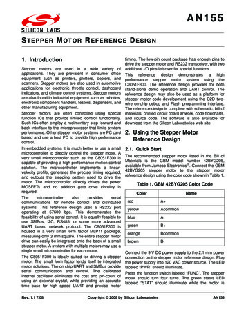
AN155The I/O pins of the MCU are by default configured asinputs with a weak pull-up transistor. This has theinadvertent effect of turning on all four transistorsmomentarily when the MCU is first powered up. This isusually not a problem for unipolar stepper motors sincethe current will be limited by the winding resistance ofthe motor. Bipolar drive will require either pull-downresistors or inverting gate drivers to accommodate thedefault pull-ups.plateau voltage may be obtained from the gate chargecurve as shown in Figure 6. Neglecting the VOL of theMCU, there is about 1.5 V across the gate drive resistor.The 330 resistors provide about 5 mA of gate drivecurrent during turn off. The gate to drain gate chargeQgd of this MOSFET is about 5 nC. This gives aswitching time of about 1 s. The measured values arevery close to this value. The measured VOL of the MCUis about 100 mV at this current.V GS, Gate-Source Votage (V)swapped during the layout phase for optimum routing tothe MOSFET gates. The stepping pattern has beenchanged accordingly. The port output current issufficient to drive most small power MOSFETs with submicrosecond switching times.P0.6 is used to drive an LED indicator that illuminateswhile the motor is moving. The C2 data signal is pinshared with the active-low switch “SW1” on pin 10. Theswitch is used to initiate a pre-programmed move sothat the board can be used without the serial interfacewhen desired.The C2 reset signal is pin shared with a manual resetbutton on pin 8. Momentarily pressing the reset buttonwill reset the MCU and turn all of the output transistorsoff. Note that the MCU will be held in reset for as long asthe reset button is held down. As a result, all four outputtransistors will be turned on while the reset button isdepressed.4.2. Power ElectronicsThe power MOSFET selected for the stepper motorreference design is the Fairchild FDS8926A. These aresmall low on-resistance power MOSFETs in an SO8package. These MOSFETs were chosen for their 30 Vrating, 3 V gate, and SO8 package. A maximum drain tosource rating of 30 V is required to drive the 12 Vstepper motor. The MOSFET chosen should becompatible with a 3 V MCU. The relevant on-resistancerating of the FDS8926A is 38 m at 2.5 V. TheseMOSFETs should easily handle 2-3 A in this application.As a practical matter, the large dc wall-mountedtransformer used with the reference design has a ratingof 1 A at 9 V. The open load voltage of this supply isabout 12 V. The output voltage decreases to 9 V at 1 A.This is sufficient to drive a small Nema 17 stepper motorwith a voltage rating of 12 V or 9.6 V and a resistance of30 or greater. A regulated lab supply can be used todrive larger stepper motors up to 3 A.The 330 resistors were chose to provide turn-off timeof just under 1 s. During the drain to source rise time,the gate to source voltage is about 1.5 V. This is calledthe plateau voltage and will depend on the thresholdand transconductance of the chosen MOSFET. The5432Vplateau 1.5 V1510152025Qg, Gate Charge (nC)Figure 6. MOSFET Gate ChargeIt is not advisable to turn off the MOSFETs too fast. Usingno resistor or too small of a resistor will result in muchfaster turn-off. The turn-off time will determine the rate ofthe change in current or di/dt. The overshoot voltage atturn-off depends on the unclamped inductance and thedi/dt. Excessive overshoot voltage could damage thepower MOSFETs. An excessively fast turn-off may alsohinder the ability of the Zener clamp to effectively protectthe Power MOSFET. The resistor also protects the MCUfrom excessive currents and voltage transients.The stepper motor reference design uses a clampcircuit to protect the power MOSFETS from excessiveovershoot voltage. A zener voltage of 27 V was chosento protect the 30 V MOSFETs. This clamp circuit is acautionary measure to protect the MOSFETs when usedwith different motors and voltage supplies. In many fixedapplications it is possible to just let the MOSFETsavalanche during turn-off. The MOSFETs must becapable of handling the peak current and energy storedin the unclamped inductance. The current and motorinductance will vary greatly from motor to motor. Theclamp circuit is useful when a single drive board mightbe used with various motors.4.3. Voltage RegulatorThe voltage regulator is an LM2973-3.3. This is a 3.3 Vlow-dropout regulator in a SOT223 package. Themaximum continuous input voltage for this device is 26 V.It is important to consider the maximum open circuitvoltage of the power supply when selecting a voltageRev. 1.19
AN155regulator. The total worst-case VDD current draw for theboard is about 25 mA. This condition occurs when bothLEDS are on and the serial port
available from Jameco Electronics . Connect the GBM 42BYG205 stepper motor to the stepper motor reference design using the color code shown in Table 1. Connect the 9 V DC power supply to the 2.1 mm power connection on the stepper motor reference design. Plug the power supply into 120 V