Transcription
Structural Insulated Panel (SIP) Engineering Design GuideFIRST EDITION 2019SIP-EDG01-19
SIP-EDG01-19 FINAL DRAFTApproval Date: 03-20-2019 FINAL DRAFTStructural Insulated Panel (SIP)Engineering Design GuideFINAL DRAFT FIRST EDITION 2019SIP-EDG01-19Structural Insulated Panel AssociationP.O. Box 39848Fort Lauderdale, Florida 33339
Copyright 2019byStructural Insulated Panel Association (SIPA)P.O. Box 39848Fort Lauderdale, Florida 33339All rights reserved. This document or any part thereofmust not be reproduced in any form without theexpress written permission of the of Structural Insulated Panel Association.The SIPA logo is a trademark of SIPA.ISBN XXXXXXXXXXThe information presented in this publication has been prepared in accordance with recognizedengineering principles and is for general information only. While it is believed to be accurate,this information should not be used or relied upon for any specific application without competentprofessional examination and verification of its accuracy, suitability, and applicability by alicensed professional engineering, designer, or architect. The publication of the materialcontained herein is not intended as a representation of warranty on the part of the StructuralInsulated Panel Association (SIPA) or of any other person named herein, that this information issuitable for any general or particular use or of freedom from infringement of any patent orpatents. Anyone making use of this information assumes all liability arising from such use.Updates and ErrataWhile every precaution has been taken to ensure the accuracy of this document, errors may haveoccurred during development. Updates and/or Errata are posted to the SIPA website atwww.sips.org.Technical inquiries may be addressed to info@sips.org.
FOREWORDWelcome to a new tool built with you, the design professional, in mind! Whether you are alreadyfamiliar with panelized construction design or exploring this system for the first time, thisStructural Insulated Panel (SIP) Engineering Design Guide will be of great value. Decades of theindustry’s collective technical wisdom and experience from scores of expert builders, designers,engineers, and wood and structural associations have gone into its compilation.Providing clear and easily accessible engineering basics to design with structural insulated panels(SIPs) is the goal of this new resource. It goes well beyond the basic prescriptive uses for SIPsthat were introduced in the International Residential Code in 2007.The Guide allows design professionals to access the innovative strength, span, and loadingcharacteristics inherent to SIPs while taking advantage of the system’s simple and fastinstallation in even complicated, multistory light commercial structures.SIPs’ continuous, low air leakage, energy-efficient insulating construction eases compliance withthe latest energy codes. Hundreds of school, multifamily, office/agricultural, and customresidential example case studies across North America can be found online via the project mapsat www.SIPs.org.The Structural Insulated Panel Association (SIPA), publisher of the SIP Engineering DesignGuide, is a non-profit trade association representing manufacturers, suppliers, dealer/distributors,design professionals, and builders committed to providing quality structural insulated panels(SIPs) for all segments of the construction industry.SIPA’s mission is to provide an industry forum to increase the acceptance and use of SIPs.Founded in 1990, SIPA has made tremendous progress advancing the vision of SIPs as thepreferred building system. Respected members of SIPA collectively produce over 80% of NorthAmerica’s SIP panels and serve as the thought leaders of the industry.AcknowledgmentsThe SIP industry appreciates the extensive analysis and work by the SIP Engineering DesignGuide’s primary developer, Eric Tompos of NTA, Inc.Eric J. Tompos, P.E., S.E., P.Eng., C.B.O., M.C.P.Eric Tompos is Executive Vice President of NTA, Inc. He is a licensed civil and/orstructural engineer in all 50 states and the provinces of Alberta and Ontario. Eric hasBachelor of Science and Master of Science degrees in Civil Engineering from PurdueUniversity and is recognized as a Certified Building Official and Master CodeProfessional by the International Code Council. He has extensive experience in thedesign and construction of factory built structures, building components, materialstesting, and quality assurance. Eric’s current focus is on structural design, codecompliance of factory built structures, development of policies related to NTA’s buildingproduct certification activities and solving code compliance issues related to new andinnovative building products.
A special thank you to SIPA Manufacturing and Supplier Members who funded this four-yearproject to create the SIP Engineering Design Guide First Edition and support its ongoingmaintenance. Additionally, much appreciation for hundreds of hours of commitment, donatedtime/resources and dedication goes to:NTA, Inc.Corey Nigh – Project CoordinatorDavid A. Tompos, LEED BD C – Project Software LeadEric J. Tompos, P.E., S.E., P.Eng., C.B.O., M.C.P. – Project Technical LeadSIPA Technical Review Committee(Chair) Tom Williamson, P.E., M.S.C.E. – Timber Engineering, LLCTodd Bergstrom, Ph.D. – AFM Corporation/R-ControlPaul Malko – Foard Panel, Inc.Dave Mensing, P.E. – Energy Panel Structures, Inc.Tom Moore, P.E. – Pinnacle Engineering, Inc.Alison Moynihan, M.S., CPHC – Foard Panel, Inc.Joe Pasma, P.E. – NederveldBrian Sielaff, P.E., S.E., P.Eng. – Tamarack Grove EngineeringBrian von Allworden, B.S.D., B.S.E. – Wright EngineersJim Whalen, P.Eng. – Plasti-Fab Ltd./InsulspanHow to Use This Guide (Intended Use)Design Specification, Commentary, and ExamplesThe SIP Engineering Design Guide has three sections – Design Specification, Commentary andDesign Examples. The Structural Insulated Panel Design Specification (SIP-EDG01-19S) isintended to be used in conjunction with competent engineering design, accurate fabrication, andadequate supervision of construction. It shall be the final responsibility of the designer to relatedesign assumptions, reference design values, and make design adjustments appropriate to the enduse. This Specification is not intended as a substitute for the experience and expertise of alicensed design professional, such as a licensed architect or engineer, nor shall the provisions ofthis design guide supersede or limit the professional judgment of a licensed design professionalin the use of SIP panels in any specific application. This Specification is intended to supplementthe SIP Manufacturer’s literature. Where conflicts exist between this Specification and theManufacturer’s literature, the Manufacturer’s literature shall govern.The Commentary on Structural Insulated Panel Design Specification (SIP-EDG01-19C)furnishes background information and references for the benefit of the design professionalseeking further understanding of the basis, derivations and limits of the Design Specification.The Design Specification is intended to be complete for normal design usage, and its provisionsare intended to be used together with the Commentary as needed.A set of Design Examples Based on Structural Insulated Panel Design Specification (SIPEDG01-19E) is provided for reference along with relevant equations to illustrate the use of thediscussed material in typical, practical applications. For convenience, a companion onlinesoftware version can be accessed via the internet without the complication of downloadingsoftware. The interactive format allows for customizing the data for a variety of needs and saving
multiple cases for future work. Baseline, conservative data for the various parameters areprovided as an initial launching point. Contact each SIP Manufacturer for their own specific datawhich should be used for actual calculation design scenarios.Interactive Online Design ExamplesEmail info@sips.org for access to the FINAL DRAFT online interactive SIP design examples.SIPA Members for Quality You Can TrustProfessionalism, experience, trust, and ethical behavior are primary reasons why users arealways encouraged to deal only with SIP Manufacturers that are members of SIPA. To ensurepanel performance, SIPA Manufacturer Members are required to have engineered load tables,insurance, and third-party QC. Go to www.SIPs.org or contact SIPA ( 1-253-858-7472,info@sips.org) for a current list of SIPA Member Manufacturers.More Technical Resources for SIPsSince their invention back in the 1940’s, Structural Insulated Panels have been well-tested andproven reliable. APA--The Engineered Wood Association recently republished its 24-page SIPProduct Guide and the ANSI Standard for SIPs which can be found for free download on boththeir and the www.SIPs.org websites. The U.S. Department of Agriculture’s Forest Products Labhas published numerous test reports. Global ISO Standards for SIP walls and roofs are available.The Builder’s Guide to SIPs in all Climate Zones by Building Science Corporation was recentlyreprinted and is available at www.SIPs.org. Numerous individual company code evaluationreports are also available including seismic and fire performance.
SIP-EDG01-19S FINAL DRAFT, SIP Design SpecificationS-1Structural Insulated PanelDesign Specification SIP-EDG01-19S Final DraftApproval Date: 8/31/2018TABLE OF CONTENTS12345678910111213Scope . S-3Notation. S-11Use Considerations . S-15Flexure . S-19Shear . S-25Compression . S-27Tension. S-31Lateral Force-Resisting Systems. S-33Combined Loads . S-45Connections and Joints . S-49Openings . S-55Reinforced Panels . S-61Shells and Folded Plate Members . S-65Structural Insulated Panel (SIP) Engineering Design Guide
S-2SIP-EDG01-19S FINAL DRAFT, SIP Design SpecificationStructural Insulated Panel (SIP) Engineering Design Guide
SIP-EDG01-19S FINAL DRAFT, SIP Design SpecificationS-31 SCOPE1.1 GeneralThis document applies to structural insulated panels (SIPs), which for the purposes of this Specificationshall be defined as an expanded polystyrene (EPS) or polyurethane (PU) foam plastic insulation coresecurely bonded between two structural facings made of wood structural panels. This document doesnot provide guidelines for assessing the adequacy of reinforcement or other materials that may beincorporated into or supplied with a SIP, such as sawn lumber or wood I-joists. These materials shall bedesigned in accordance with the appropriate code adopted design standards.It is intended that this document be used in conjunction with competent engineering design, accuratefabrication, and adequate supervision of construction. It shall be the final responsibility of the designerto relate design assumptions, reference design values and to make design adjustments appropriate to theend use. This Specification is not intended as a substitute for the experience and expertise of a licenseddesign professional, such as a licensed architect or engineer, nor shall the provisions of this design guidesupersede or limit the professional judgment of a licensed design professional in the use of SIP panels inany specific application.This Specification is intended to supplement the SIP manufacturer’s literature. Where conflicts existbetween this Specification and the manufacturer’s literature, the manufacturer’s literature shall govern.1.2 Design ProceduresThis document provides design provisions for Allowable Strength Design (ASD), Load and ResistanceFactor Design (LRFD), Limit States Design (LSD), and Average Divided-By-Three (ADT) designphilosophies. Designs shall be made according to one of these design methods, as appropriate.This Specification is not intended to preclude the use of materials, assemblies, structures or designs notmeeting the criteria herein, where it is demonstrated by analysis based on recognized theory, full-scale orprototype loading tests or extensive experience in use that the material assembly, structure or design willperform satisfactorily in its intended use.1.2.1 Loading AssumptionsSIP buildings and their components shall be designed and constructed to safely support all anticipatedloads. This Specification is predicated on the principle that the loading assumed in the design representsactual conditions, except as permitted by the following approximations:1.2.SIP panels utilizing Type S splines, continuously supported at each support location and having awidth greater than 12-inches may be designed on the basis of a one foot panel width (per foot basis)unless otherwise specified by the SIP manufacturer.Reaction forces from equally spaced and equally loaded repetitive members, such as trusses andjoists, may be considered an equivalent uniform line-load in design provided the individualmembers are spaced 24-inches on center or less and fastened to a rim board or similar membercapable of distributing the load to the SIP.1.2.2 Design LoadsMinimum design loads shall be in accordance with the building code under which the structure isdesigned, or where applicable, other recognized minimum design load standards.Structural Insulated Panel (SIP) Engineering Design Guide
S-4SIP-EDG01-19S FINAL DRAFT, SIP Design Specification1.2.3 Load CombinationsCombinations of design load and forces, and load combinations factors, shall be in accordance with thebuilding code under which the structure is designed, or where applicable, other recognized minimumdesign standards. Where load combinations consider loads of different durations, additional loadcombinations should be considered, as necessary, to ensure that the worst-case combination of loadduration and time effect factor is considered. The ADT design method shall be used in conjunction withthe allowable stress design load combinations found in ASCE 7.1.3 TerminologyUnless otherwise expressly stated, the following words and terms shall, for the purposes of thisSpecification, have the meanings provided in this section. Terms not defined in this section shall beassigned the ordinarily accepted meaning such as the context implies.ADOPTED WOOD DESIGN SPECIFICATION. A design specification, such as the NationalDesign Specification for Wood Construction (NDS) or CSA Standard O86, Engineered Design inWood, that has been adopted by the local authority having jurisdiction.BOUNDARY ELEMENTS. Diaphragm and shear wall boundary members to which thediaphragm transfers forces. Boundary members include chords and drag struts at diaphragm andshear wall perimeters, interior openings, discontinuities, and reentrant corners.CHARACTERISTIC VALUE. The structural property estimate, typically determined aspopulation mean for properties related to serviceability design limits and determined as tolerancelimit (5th percentile with 75% confidence) for properties related to strength design limits, asestimated from the test data that is representative of the population being sampled.CONNECTION. A joining together of two or more separate materials across an interface by meansof mechanical interlock or chemical adhesion. Unless otherwise specified, connections described inthis Design Guide are limited to those connections made between the facing of a SIP panel andanother material, such as, but not limited to, a spline. For the purposes of this document, connectionsare classified as follows:CONNECTION, TYPE A (ADHESIVE/SEALANT). A connection formed by use of an adhesiveor adhesive sealant with or without the presence of mechanical fasteners. A mechanical connectionshall be classified as a Type A Connection when an adhesive or sealant is applied to the fayingsurfaces joined by the mechanical fasteners regardless of whether the strength contribution of theadhesive or adhesive sealant is considered.CONNECTION, TYPE C (CONVENTIONAL). A mechanical connection composed ofconventional materials and assembled in a manner that permits the strength of the connection to bedetermined in accordance with an accepted engineering design methodology or otherwise conformsto prescriptive connection requirements. A Type C Connection is generally created when amechanical fastener is inserted through a SIP facing into a Type R Spline or Type RT Spline.CONNECTION, TYPE S (SIP). A mechanical connection composed of conventional or nonconventional materials and assembled in a manner that does not permit the strength of theconnection to be determined in accordance with an accepted engineering design methodology anddoes not conform to prescriptive connection requirements. A Type S Connection is generally createdwhen a mechanical fastener is inserted through a SIP facing into a Type S Spline.Structural Insulated Panel (SIP) Engineering Design Guide
SIP-EDG01-19S FINAL DRAFT, SIP Design SpecificationS-5CONNECTION, TYPE SD (SIP-DUCTILE). A Type S Connection that has been shown by testingor analysis to exhibit a ductile mode of failure. In Type SD Connections, except where thin mildcarbon steel materials are joined, the fastener connecting the material must be shown to yield prior tofailure of the connected materials. Wood-to-wood connections analyzed using the National DesignSpecification for Wood Construction (NDS) yield mode equations must exhibit a Mode III or ModeIV yield modes to be classified as ductile, Type SD Connections. Where wood products are used, aType SD Connection is generally created when a ductile mechanical fastener, such as a nail, isinserted through a SIP facing into a Type C or Type S Spline that provides a minimum dowel bearinglength of 6 times the fastener diameter.CONVENTIONAL MATERIALS. Building materials conforming to standards recognized by theadopted building code or as adopted by the authority having jurisdiction. Examples of conventionalmaterials include dimension lumber, engineered wood products and cold-formed steel.CORE. The light-weight middle section of the SIP composed of foam plastic insulation, whichprovides the link between the two structural panel facings and provides the required thermalinsulation for the wall, supplies buckling resistance to the two panel facings under axial loads, andcontributes to the shear and bending resistance of the panel under transverse and lateral loads.CORE, EXPANDED POLYSTYRENE (EPS). The letter designation for the molded expandedpolystyrene thermal insulation classified by this standard and is defined as cellular plastic productmanufactured from pre-expanded polystyrene beads subsequently molded into blocks resulting in aproduct which is rigid with closed cellular structure.CORE, JOINT. A discontinuity created within the SIP core at the interface between individual corepieces that results when more than one piece of preformed core material is used within a singlepanel.CORE, POLYURETHANE INSULATION (PU). A rigid cellular plastic material that is formedby the catalyzed reaction of polyisocyanates and polyhydroxyl compounds, expanded with blowingagents, resulting in a product that is a predominantly closed cell product. Polyurethane cores may beexpanded between the facers and self-adhered to the facing or may be performed and bonded with alaminating adhesive.CORE, VOID. A discontinuity within the SIP core that consists of an empty space/volume.DIAPHRAGM. Roof, floor or other membrane or bracing system acting to transfer lateral forces tothe vertical resisting elements.FACING. The material that forms both exterior layers of the SIP. The facings provide flexuralstrength and stiffness to the SIP assemblage under transverse loading and provide axial strengthunder in-plane compressive and tensile loading.FOLDED PLATE. A class of shell structure formed by joining flat SIPs along their edges to createa three-dimensional spatial structure.LAMINATING ADHESIVE. The adhesive used to bond the facings to the core; exists as a thin-filmbetween the materials being joined.LINTEL. A structural element acting as a header supporting gravity loads above an opening.Structural Insulated Panel (SIP) Engineering Design Guide
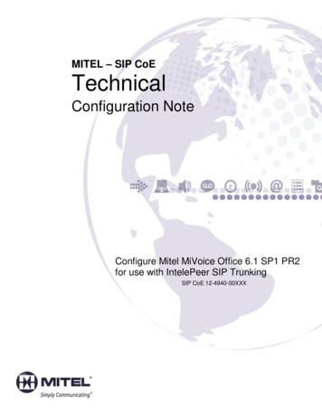
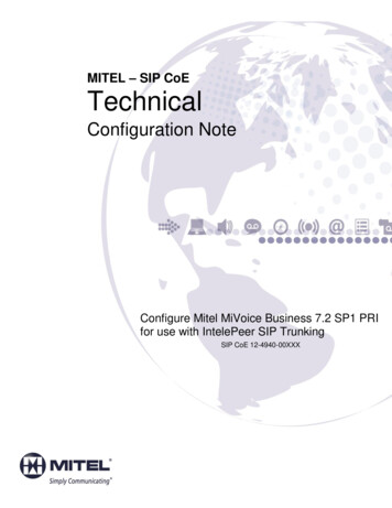
S-6SIP-EDG01-19S FINAL DRAFT, SIP Design SpecificationMANUFACTUER’S LITERATURE. Manufacturer specific specifications, details and/or designedinformation. Such information shall be regarded as applying only to the panels produced by themanufacturer supplying the literature and shall not be used in conjunction with SIPs supplied byother manufacturers.OPENING, DOOR/WINDOW OPENING. A discontinuity in a SIP assembly where one or bothfacings are not present thereby creating a condition where a load path must be provided to transferthe applied load(s) around the discontinuity.PIER. A section of a wall, comprised of SIPs, between windows or other adjacent openings.SEALANT. Material used for sealing SIPs at spline, plate, and other connections to reduce airinfiltration.SEISMIC FORCE-RESISTING SYSTEM. That part of the structural system that has beenconsidered in the design to provide the required resistance to the code required seismic forces.SHEAR WALL. A wall designed to resist lateral forces acting in the plane of the wall.SHEAR WALL, PERFORATED. A shear wall with openings in the wall that has not beenspecifically designed and detailed for force transfer around wall openings.SHEAR WALL, SEGMENTED. A shear wall consisting of individual full-height wall segmentswith no openings within an individual full-height segment.SHELL. Three-dimensional spatial structure made up of one or more curved or folded plates. Shellsare characterized by their three-dimensional load-carrying behavior, which is determined by theirgeometry, form, the manner in which they are supported, and by the nature of the applied load.SPLINE. Elements installed, at the factory or at the jobsite, into recesses in the SIP core, tointerconnect adjacent SIP panels utilizing a tongue-and-groove arrangement. For the purposes of thisdocument, splines are classified as follows:SPLINE, BLOCK. A spline consisting of the same material as the structural insulated panel facingsbonded with the same foam core to form a block with overall thickness equal to the core thickness ofthe two structural insulated panels to be connected that fits into a recess at the vertical edges of thetwo structural insulated panels to be connected (see Figure 1.3-1).Figure 1.3-1: Block SplineStructural Insulated Panel (SIP) Engineering Design Guide
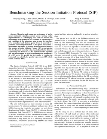
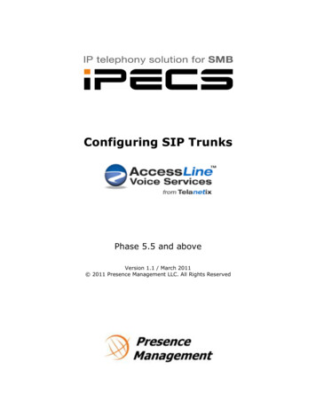
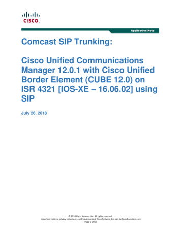
SIP-EDG01-19S FINAL DRAFT, SIP Design SpecificationSPLINE, SURFACE. A pair of wood structural panels of the same material as the structuralinsulated panel facings that fit into grooves cut into the foam core at the vertical edges of the twostructural insulated panels to be connected (see Figure 1.3-2).Figure 1.3-2: Surface SplineSPLINE, TYPE R (REINFORCING SPLINE). A Type R Spline is a discrete element, not integralwith the SIP, having accepted design properties established separately from the SIP panel. This typeof spline reinforces the SIP panel and provides significant axial and transverse (out-of-plane)strength and stiffness. Examples of Type R Splines include, but are not limited to: solid sawn lumber,engineered lumber, cold-formed steel studs or channels (see Figure 1.3-3).Figure 1.3-3: Reinforcing SplineSPLINE, TYPE RT (TRANSVERSE REINFORCING SPLINE). A Type R Spline that providesonly transverse (out-of-plane) reinforcement. Examples of Type RT Splines include, but are notlimited to, wood I-Joists.SPLINE, TYPE S (SIP SPLINE). A spline comprised of an element or elements that do notcontribute significant additional strength or stiffness (axial or transverse) to the assembled SIPs.Examples of Type S Splines include but are not limited to: surface splines and block splines.STRENGTH, DESIGN. Nominal strength multiplied by a strength reduction factor (LRFD, LSD)or divided by a factor of safety (ASD, ADT).STRENGTH, NOMINAL. Strength of a member or cross-section calculated in accordance with therequirements and assumptions of the strength design methods of this Specification (or the referencedocuments) before application of any strength-reduction factors (LRFD, LSD) or factors of safety(ASD, LSD).STRENGTH, REQUIRED. Minimum loads, forces, internal moments and stresses must be resistedby a member subjected to the combinations of loads required by the adopted building and applicableto the design method used (i.e. ASD, ADT, LRFD, LSD).STRENGTH AXES. The two possible directions of loading in the plane of the SIP panel that areorthogonal to each other and have distinct mechanical properties.Structural Insulated Panel (SIP) Engineering Design GuideS-7
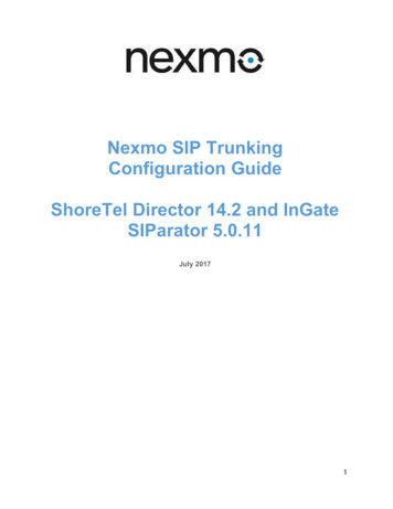
S-8SIP-EDG01-19S FINAL DRAFT, SIP Design SpecificationSTRENGTH AXIS, STRONG. The direction of loading in which the applied stress is appliedparallel to the strength axis having the greatest mechanical properties.STRENGTH AXIS, WEAK. The direction of loading in which the applied stress is applied parallelto the strength axis having the lesser mechanical properties.STRINGER. Elements or components that are integral with the SIP (factory-installed within theSIP) parallel to the panel span. Also referred to as intermediate stiffeners or structural splines.STRUCTURAL INSULATED PANEL (SIP). A structural member composed of a light-weightinsulating core material, such as expanded polystyrene foam (EPS) or polyurethane foam (PU),securely bonded to wood structural panel facings to form a composite assembly. SIP panels may beused as walls, roofs, and floors in buildings.SUPPORT CONDITION, END-SUPPORTED. Support condition where load is applied to thesupported face. Mode of failure changes from a shear failure to a tensile/peeling failure of the topfacing (Figure 1.3-6). The strength contribution of the bottom facing is dependent on the withdrawalstrength of the fasteners from the supporting member. This support condition is commonly seen inwall panels.Figure 1.3-6: End-SupportedSUPPORT CONDITION, BLOCKED FACE-BEARING. Support condition where load isapplied to the face opposite a bearing support (Figure 1.3-4). A solid block provided at the bearinglocation prevents local crushing of the core. This support condition generally achieves the greateststrength and produces a shear failure through the core.Figure 1.3-4: Blocked Face-Bearing SupportSUPPORT CONDITION, UNBLOCKED FACE-BEARING. Support condition where load isapplied to the face opposite a bearing support (Figure 1.3-5). No solid block is provided at thebearing location which permits crushing of the core. This support condition may produce either ashear failure or a bearing failure. Additionally, the local deflection of the core becomes a designconsideration. This support condition is commonly seen in roof panels.Structural Insulated Panel (SIP) Engineering Design Guide
SIP-EDG01-19S FINAL DRAFT, SIP Design SpecificationFigure 1.3-5: Unblocked Face-Bearing SupportWOOD STRUCTURAL PANEL. A panel product composed of oriented strand board (OSB) orplywood in conformance with the performance requirements of DOC PS1 or DOC PS2 in the U.S. orCSA O121, CSA O151, or CSA O325 in Canada.Structural Insulated Panel (SIP) Engineering Design GuideS-9
S-10SIP-EDG01-19S FINAL DRAFT, SIP Design SpecificationStructural Insulated Panel (SIP) Engineering Design Guide
SIP-EDG01-19S FINAL DRAFT, SIP Design SpecificationS-112 NOTATIONSome definitions in the list below have been simplified in the interest of brevity. In all cases, thedefinitions given in the body of the Specification govern. Except where otherwise noted, thesymbols used in this document have the following meanings:Α Area of diaphragm or shear wall chord cross-section (in.2)Af Total cross-sectional area of the facing material (in.2)An Net tensile area of panel facings (in.2)Ao Total area of openings in the shear wall where individual openings are calculated as theopening width times the clear opening height. Where sheathing is not applied to theframing above or below the opening, these areas shall be included in the total area ofopenings. Where the opening height is less than h/3, an opening height of h/3 shall beused (ft2)Αv Shear area (in.2)b Shear wall or shear wall segment length (ft)b Bearing width perpendicular to panel span (in.)bc Shear wall width at story c (ft)C Compression chord force in shear wall (lbf)CAR Aspect ratio adjustment factor from Section 8.5.6CC Connection correction factor from Section 8.5.5Ce Eccentric load factor, Equation 6.3.1-4.CFv Depth factor for shear, Section 5.3.1Ci Crushing-buckling interaction factor from Section 6.3.1CO Perforated shear wall adjustment factor from Sectio
The SIP Engineering Design Guide has three sections – Design Specification, Commentary and Design Examples. The Structural Insulated Panel Design Specification (SIP-EDG01-19S) is intended to be used in conjunction with competent engineering design, accura